Advertisement
INSTALLATION INSTRUCTIONS
CPV-TP2
Thermostatic / Balance Pressure
Shower Valve
CPV-TP2-DV
Thermostatic / Balance Pressure
Shower Valve
with Integral Diverter
92-CPV-TP2-01
NEED HELP?
For additional assistance or service please contact:
ROUGH IN VERTICAL REFERENCE
TUB/SHOWER
78"
(1981mm)
21"
(533mm)
4"
(102mm)
TO TOP OF
TUB LEDGE
TOOLS & SUPPLIES NEEDED
Pencil
Measuring
Level
Tape
Drill
Phillips
Mounting
Drive Bit
Hardware
(not included)
Flat Tip
Phillips
Slip Joint
Screwdriver
Screwdriver
Wrench
Wrench
Socket
9/16"
Tubing
Wrench
(14mm)
Cutter
Deep Well Socket
Thread Seal
Eye Protection
Tape
www.speakman.com
800-537-2107
SHOWER ONLY
78"
(1981mm)
48"
(1219mm)
IMPORTANT
SAFETY TIPS:
Be sure to read and understand all instructions
before beginning installation.
Inspect all connections after installation.
Cover the drain to avoid loss of parts.
Be sure to wear proper eye protection.
Do NOT over tighten any connections or damage
may occur.
Shut OFF water supplies before beginning
installation.
Observe all local plumbing and building codes.
Pipe
VALVE SPECIFICATIONS:
This Valve has an operating range of 20-80 psi.
This Valve is engineered to be used in conjunction
with a Shower Head rated at 1.35 gpm (5.1 L/min)
or higher flow rate.
Maximum water pressure: 125 psi static.
Solder Kit
Minimum water pressure: 20 psi flowing.
Minimum Cold Supply Temperature: 40°F.
Maximum Hot Supply Temperature: 160°F.
Minimum Hot Supply Temperature: 5°F above set
point.
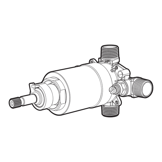
Determine the mounting depth of the Valve referencing the diagrams below. The Protective Cover on the
Valve has reference markings showing where the Valve should align with the Finished Wall Surface. The
distance from the Finished Wall Surface to the centerline of the Valve Inlets/Outlets MUST fall between
2-1/2" Minimum and 3-1/2" Maximum.
FINISHED
WALL
SURFACE
Risk of personal injury. Do NOT use the Valve
without properly adjusting the Temperature Limit
Stop (TLS) as outlined in this installation
manual.
Ensure proper structure is in place to support
the Valve and plumbing during use.
MAINTENANCE
Your new product is designed for years of
trouble-free performance.
This type of valve must be cleaned and
maintained on a regular basis. Periodic
maintenance should be performed at least
every 12 months or after any changes have
been made to the building's plumbing system.
Valves that are installed outdoors should be
winterized by removing all of the internal parts
and removing any standing water from the
valve. Quarterly the maximum hot temperature
setting (TLS) should be checked and adjusted
accordingly.
FINISH MAINTENANCE:
Keep the surface finish looking new by cleaning
it periodically with a soft cloth. Avoid abrasive
cleaners, steel wool, and harsh chemicals as
these will dull the finish and void your warranty.
ROUGH IN DEPTH REFERENCE
THE MINIMUM ALLOWED
ALIGNS WITH THE
FINISHED WALL AT
THE MAXIMUM ALLOWED
ROUGH IN DEPTH
2-½"
64mm
MINIMUM
FINISHED
WALL
SURFACE
CAUTION
ALIGNS WITH THE
FINISHED WALL AT
ROUGH IN DEPTH
3-½"
89mm
MAXIMUM
Advertisement
Table of Contents

Subscribe to Our Youtube Channel
Related Manuals for Speakman CPV-TP2


Summary of Contents for Speakman CPV-TP2
- Page 1 INSTALLATION INSTRUCTIONS TOOLS & SUPPLIES NEEDED IMPORTANT CAUTION CPV-TP2 Pencil Measuring Level SAFETY TIPS: Risk of personal injury. Do NOT use the Valve Tape Be sure to read and understand all instructions Thermostatic / Balance Pressure without properly adjusting the Temperature Limit before beginning installation.
- Page 2 SITE PREPARATION PREPARE VALVE FOR MOUNTING Referencing the rough in guides, install a 1” x 4” Cross Brace between the Vertical Studs at the Remove O-Ring and Protective Cover from Valve. Set aside for future use. proper height and depth outlined. Use a Level to ensure the front surface of the Cross Brace is perfectly vertical.
- Page 3 PLUMB SHOWER HEAD OUTLET PLUMB TUB/ACCESSORY OUTLET Make plumbing connections to the Shower Head Outlet of the Valve. Shower Head Outlet Make plumbing connections to the Tub/Accessory Outlet of the Valve. Tub/Accessory Outlet Connection is 1/2” NPT Male (1/2” Copper Sweat). See “Rough In Vertical Reference” for the Connection is 1/2”...
-
Page 4: Back To Back Installation
BACK TO BACK INSTALLATION FLUSH SYSTEM / CHECK FOR LEAKS Your Shower Valve has the ability to be mounted back-to-back with another Valve in a shared Temporarily place the Spindle Adapter (A) on to the Valve Spindle. Rotate the Valve Spindle space. -
Page 5: Product Warranty
Consumer/Residential: Limited Lifetime Warranty Commercial Use: 5 Year Limited Warranty Speakman warrants to its purchasers only (“Buyer”) that goods are sold free from defects in materials and workmanship and conform to Speakman’s specifications at the time of manufacturing, provided the goods are properly installed and maintained. -
Page 6: Repair Parts
VALVE REPAIR CARTRIDGE RPG49-118834 WITH LOWER SEALS AND VALVE BODY O-RING VALVE BODY O-RING RPG05-119153 REPLACEMENT BONNET CPV-TP2 ROUGH-IN DIAGRAM COMPLIANCE ASME A112.18.1 / CSA B125.1 ASSE 1016 / ASME A112.1016 / CSA B125.16 1" 25mm HOLE FOR SHOWER ARM CONNECTIONS 6'-6"... - Page 7 CPV-TP2-DV ROUGH-IN DIAGRAM COMPLIANCE ASME A112.18.1 / CSA B125.1 ASSE 1016 / ASME A112.1016 / CSA B125.16 1" 25mm HOLE FOR SHOWER ARM CONNECTIONS 6'-6" [2 METERS] TO FLOOR HOT / COLD Inlets: 1/2” NPT Male 5-1/2" (140MM) DIA. 1/2" NPT MALE HOLE FOR 1/2"...
Need help?
Do you have a question about the CPV-TP2 and is the answer not in the manual?
Questions and answers