Table of Contents
Advertisement
Quick Links
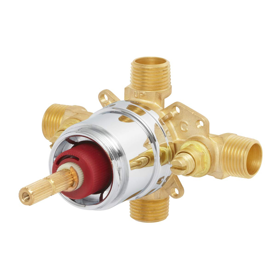
INSTRUCTIONS FOR MODELS
CPV-PB-PXE
CPV-PB-DV-PXE
For additional assistance or service please contact:
SPEAKMAN
®
Company
400 Anchor Mill Road
New Castle, DE 19720
800-537-2107
customerservice@speakman.com
www.speakman.com
92-CPV-PB-PXE-01
3
Shut off the water supply to the Tub and Shower. Verify that the hole sizes and
positions in the wall are correct:
A. The shower and tub spout outlet holes should be 1" diameter.
B. To determine the Valve mounting depth, see STEP 4.
C. The distance from the Valve mounting surface to the finished wall MUST be
between 3-1/8" to 4-1/8". Position the Valve Body ❶ correctly in the wall with
the "UP" pointing up. The 1'-9" minimum from the Valve Body to the Tub Spout is
required for proper operation.
ØSee Step 4
1'-9"
(533mm)
Tub/Shower
4"
(102mm)
Tub/Shower
Ø1" Hole for Tub Spout
TOOLS AND SUPPLIES
Pencil
Keyhole
Adjustable
Saw
Wrench
Slip Joint
Solder Kit
Measuring
Wrench
Socket
9/16" (14mm)
Wrench
Deep Well Socket
NOTE: PEX tools and supplies NOT INCLUDED.
Expansion
PEX Expansion
Sleeve
Tool
HELPFUL TOOLS & SUPPLIES:
Thread Seal
Phillips
Tape
Screwdriver
Level
Safety
Glasses
4
Ø1" Hole for Shower Arm
6'-6" (1.4 meters)
Tub/Shower
&
Shower Only
5
4'-6" (1.4 meters)
Shower Only
IMPORTANT
• Be sure to read instructions thoroughly before
Pipe
beginning installation.
Wrench
• Be sure to have properly adjusted the Temperature
Limiting Stop (TLS) as outlined in this Installation
Manual.
• Inspect all connections after installation of valve.
• This valve has an operating range of 20-80 psi.
• This valve is designed to be used in conjunction
Tape
with a shower-head rated at 1.75 gpm (6.6 L/min)
or higher flow rate.
• NOTE: This installation manual covers several
models of valves. While the appearance of your
valve may differ from those shown, the installation
method is the same.
• Maximum water pressure: 125 psi static; minimum
13/16" (20mm)
water pressure: 20 psi flowing; minimum cold
Deep Well Socket
supply temperature: 40 °F; maximum hot supply
temperature: 160 °F; minimum hot supply
temperature: 5 °F above set point.
SAFETY TIPS
Cover your drain to prevent loss of parts. Be sure to
wear eye protection while cutting pipe.
MAINTENANCE
PEX
Cutter
Your new Shower/Bath Valve is designed for years of
trouble-free performance. Keep it looking new by
cleaning it periodically with a soft cloth. The use of
harsh chemicals and abrasives on any of the Speakman
custom finish products may damage the finish and void
the product warranty. Please be sure to only use
approved cleaners. Please contact Speakman for any
clarification of acceptable cleaners.
This type of valve must be cleaned and maintained on a
regular basis. Periodic maintenance should be
Tubing
performed at least every 12 months or after any
Cutter
changes have been made to the building's plumbing
system. This maintenance should include removing and
cleaning the spring check stop components. Make sure
the stop poppet in each stop moves freely. Valves that
are installed outdoors should be winterized by removing
all of the internal parts and removing any standing
water from the valve. Quarterly the maximum hot
temperature setting (TLS) should be checked and
adjusted accordingly.
Drill
WARRANTY
Warranty information can be found at:
www.speakman.com
Install the Rough-In Template over the Shower Valve being sure the Rough-In Template sits flush against Valve Body. Following
the rough-in dimensions for your model of valve (located ot the end of this manual) as well as the markings on the supplied
Rough-In Template, install valve at proper depth. The distance from the Valve mounting surface to the finished wall MUST be
between 3-1/8" - 4-1/8". See images below for reference.
MINIMUM MOUNTING DEPTH
THE BACK SURFACE OF THE
SHOWER OUTLET
ROUGH-IN TEMPLATE IS
FLUSH WITH OR INSIDE
THE VALVE ACCESS HOLE.
TUB OUTLET
ROUGH-IN TEMPLATE
FINISHED WALL SURFACE
3-1/8" MINIMUM
MOUNTING DEPTH
Mounting Structure behind the wall must
be capable of supporting the Valve in
use. Following the rough-in dimensions
for your model of valve (located ot the
end of this manual), reference the
diagram below for the installation and
placement of the bracing within a 2"x4"
wall, using a 1"x4" brace. Mounting
hardware is not included.
1
Remove the two Screws with a Philips Head
Screwdriver then slide the Rough-In Template off
the Valve.
2
Referencing the supplied rough-in dimensions
(located at the end of this manual), determine the
preferred location of Valve. Align the supplied
Rough-In Template with this location and trace
outline of Template onto wall. Using a Keyhole
Saw or similar tool, cut along traced line and
remove this section of wall.
MAXIMUM MOUNTING DEPTH
THE FRONT EDGE OF THE
ROUGH-IN TEMPLATE IS
FLUSH WITH OR OUTSIDE
THE VALVE ACCESS HOLE.
ROUGH-IN TEMPLATE
FINISHED WALL SURFACE
1" X 4"
DIMENSIONAL
LUMBER
4-1/8" MAXIMUM
MOUNTING DEPTH
14 1
"
2
368mm
SHOWER OUTLET
TUB OUTLET
1" X 4"
DIMENSIONAL
LUMBER
4 1
"
2
114mm
Advertisement
Table of Contents

Related Manuals for Speakman Sentinel Mark II


Summary of Contents for Speakman Sentinel Mark II
- Page 1 The use of Saw or similar tool, cut along traced line and harsh chemicals and abrasives on any of the Speakman remove this section of wall. custom finish products may damage the finish and void the product warranty.
- Page 2 PIPE FITTING INSTALLATION If your installation is for a shower only, apply Thread Seal Tape in a clockwise direction to the Tub Outlet Port ❶ and install the included Plug Cap. Wrench tighten. If you are performing a pipe fitting installation, apply Thread Seal Tape around the pipe threads in a clockwise direction.
- Page 3 PEX (COLD EXPANSION) INSTALLATION INSTRUCTIONS Use Plastic Tubing Cutters (not included), to cut the ASTM F1960 Slide the correct size i.e., ½” ASTM F1960 compliant PEX Sleeve Use ASTM F1960 Grip Expansion Tool for expanding PEX tube compliant PEX Tubing ❶ to length. Ensure that a good square (90°) ❶...
- Page 4 35-53 in*lb. 6) Open the Integral Stops of the Valve by turning the Stop Spindles counter- clockwise. Check for leaks. 7) Reassemble the Trim Parts. SPEAKMAN CPV-PB-PXE / CPV-PB-DV-PXE REPAIR PARTS ® I I TEM # P P ART #...
- Page 5 SPEAKMAN CPV-PB-PXE ROUGH-IN DIAGRAM ® NOTES: COMPLIANCE: ASME A112.18.1/CSA B125.1 1" 25mm ASSE1016/ASME A112.1016/CSA B125.16 HOLE FOR SHOWER ARM 6'-6" [2 METERS] TO FLOOR CONNECTIONS: 5-1/2" (140MM) DIA. 1/2" NPT MALE Hot/Cold Inlets: ½” F1960 Cold HOLE FOR 1/2" SWEAT...
Need help?
Do you have a question about the Sentinel Mark II and is the answer not in the manual?
Questions and answers