
Related Manuals for 3M SCOTT VISION C5


Summary of Contents for 3M SCOTT VISION C5
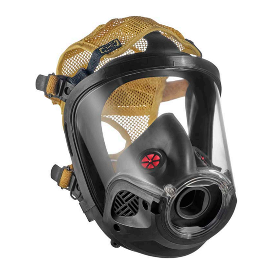
- Page 1 OPERATING & MAINTENANCE INSTRUCTIONS 3M™ SCOTT™ VISION C5 FULL FACEPIECE READ ALL INSTRUCTIONS BEFORE USE P/N 595390-01 Rev B 202003...
- Page 2 If you have any questions or concerns regarding these regulations, contact 3M at 1-800-247-7257 (704-291-8300 outside the continental United States). Questions or Concerns If you have any questions or concerns regarding use of this equipment, contact your authorized 3M distributor, or contact 3M at 1-800-247-7257 (704-291-8300 outside the continental United States) or ScottTechSupport@mmm.com.
-
Page 3: Table Of Contents
Appendices ............................6 Before You Begin ............................6 Maintenance and Repairs ........................6 Retirement Criteria and Considerations ..................6 Safety Information ........................7 All 3M Scott Fire & Safety Products...................... 7 3M Scott Full Facepieces.........................8 Warnings and Cautions ..........................8 Chapter 1 Introduction ...........................11 Before You Begin ............................11 Overview .............................. - Page 4 CONTENTS P/N 595390-01 Rev B 202003...
-
Page 5: About This Manual
3M provides manuals for individuals with different levels of training. This manual is written for Trained Operators. • A Trained Operator is an individual who has had minimum-level training in the use of 3M Scott Fire & Safety equipment in an immediately dangerous to life or health (IDLH) environment. This individual is often a firefighter or the wearer of an SCBA. -
Page 6: Appendices
When performing any maintenance checks or services on any 3M Scott Fire & Safety product or device, proceed only as far as necessary and as instructed by this manual. -
Page 7: Safety Information
If a discrepancy or malfunction cannot be corrected using the procedures contained within this manual, the product must be tagged to indicate that it is unserviceable and referred to a 3M Certified Technician II for evaluation and repair. -
Page 8: 3M Scott Full Facepieces
Manager or Safety Coordinator must assist the user in selecting the correct facepiece size relative to the user’s facial features and dimensions. Prior to use, fit testing must be performed with any approved 3M Scott accessory that will be installed on the facepiece, such as communications devices or thermal imaging systems. See “Appendix A: Facepiece Fitting”... - Page 9 SAFETY INFORMATION WARNING To reduce the risks associated with loss of air supply, exposure to contaminants, and oxygen-deficient atmospheres, which, if not avoided, could result in serious injury or death: • Do not store the facepiece with the regulator attached. Storing the facepiece in this way may cause damage.
- Page 10 • Do not alter or repair the facepiece beyond the scope of these instructions. • Use only 3M-approved parts. • Follow the regular operational inspection procedures exactly. If there are any operational malfunctions, remove the respirator from service and tag for repair by authorized personnel.
-
Page 11: Chapter 1 Introduction
Rev B 202003 CHAPTER 1 P/N 595390-01 INTRODUCTION This chapter describes the 3M Scott Vision C5 full facepiece and its major components. Before You Begin Carefully read “Safety Information” on page 7 before beginning any of the procedures in this manual. - Page 12 Quantitative Fit Test (QNFT) protocols deemed acceptable by those standards. For quantitative fit testing, 3M Scott Fire & Safety facepieces require use of a Fit Test Adapter or equivalent and appropriate negative pressure testing equipment. A Mask Seal Kit may also be required to attain a proper fit. See “Appendix A: Facepiece Fitting”...
-
Page 13: Chapter 2 Inspection
P/N 595390-01 INSPECTION This chapter describes how to perform a regular operational inspection of a 3M Scott Vision C5 full facepiece. Follow the procedures in this chapter when you first receive the facepiece and during daily or periodic inspection of the facepiece: •... -
Page 14: Performing Operational Testing
Figure 2-1 Checking the nose cup installation Performing Operational Testing See the operating and maintenance instructions provided with your 3M Scott Air-Pak respirator for full details about operational testing of the respirator with the facepiece. You should perform operational testing before each use of the respirator. -
Page 15: Chapter 3 Donning
P/N 595390-01 DONNING This chapter provides the basic instructions for donning the 3M Scott Vision C5 full facepiece. Training and practice with the equipment are required before operation to ensure that you are completely familiar with its operation. Instructions for donning the facepiece are divided into the following sections: •... - Page 16 DONNING Adjust the head straps to the full outward position. See Figure 3-1. Figure 3-1 Adjusting the head straps to the fill outward position 2 Hold the facepiece in one hand. Fold the head harness over the lens (see Figure 3-2), or hold the head harness up and out of the way with the other hand.
- Page 17 DONNING THE FACEPIECE Ensure that the chin is properly located in the chin pocket of the facepiece throughout the donning process. 6 Smooth the head harness over the head and ensure that straps are lying smooth and flat against the head and neck with no twists. See Figure 3-5.
- Page 18 DONNING 10 Smooth the head harness down the back of the head and make sure the net is flat against the head. If necessary, adjust the bottom of the head harness to sit below the crown of the head. See Figure 3-8.
- Page 19 DONNING THE FACEPIECE Head harness not centered Twisted head harness strap Head harness too high Facepiece too low Figure 3-10 Donning problems OSHA standard 29 CFR 1910.134 requires teams of at least two people when entering into and operating in an IDLH atmosphere.
- Page 20 DONNING P/N 595390-01 Rev B 202003...
-
Page 21: Chapter 4 Cleaning & Maintenance
Rev B 202003 CHAPTER 4 P/N 595390-01 CLEANING & MAINTENANCE This chapter provides instructions for cleaning and storing the 3M Scott Vision C5 full facepiece. • “Before You Begin” on page 21 • “Cleaning the Facepiece” on page 21 Before You Begin Carefully read “Safety... - Page 22 • Bleach stronger than a 3% solution in water • Cleaners containing quaternary ammonium compounds other than those recommended by 3M • Solvents such as acetone, paint and lacquer thinner, benzene, or dry-cleaning fluid In addition, do not do the following: •...
-
Page 23: Maintenance
Kevlar upper strap, head harness, Vision C5 804178-03 Kevlar lower strap, head harness, Vision C5 Table 4-1 Available parts for the 3M Scott Vision C5 Facepiece Uninstalling and Installing the Nose Cup Assembly To uninstall the nose cup assembly Reach inside the facepiece and, using only your fingers, flex the exterior surface of the nose cup from the two voicemitter ducts;... - Page 24 CLEANING & MAINTENANCE 4 Check the nose cup to verify the following: • The inhalation check valves are facing up and toward the inside of the nose cup. • The nose cup is properly seated on the retaining posts and around the voicemitter ducts. •...
-
Page 25: Uninstalling And Installing The Head Harness & Straps
MAINTENANCE Uninstalling and Installing the Head Harness & Straps Buckle release lever Buckle roller Head harness Pull loop Head harness buckle Figure 4-6 Head harness and straps To uninstall and install the head harness Locate one of the four buckles positioned around the facepiece holding the head harness straps. See picture A in Figure 4-6. -
Page 26: Installing The Neck Strap
CLEANING & MAINTENANCE 6 Thread each strap through the slot closest to the buckle attachment with the pull loop sewn side down. Thread over the buckle roller and back through the slot between the buckle roller and the release lever. When assembled properly, the pull loop will be above the strap. -
Page 27: Appendix A Facepiece Fitting
Any approved 3M Scott Fire & Safety accessories that will be used with the respirator, such as a communications device installed on the facepiece, must be in place during fit testing. If changing from a standard facepiece to a facepiece with an installed accessory, such as a communications device, it is recommended that a new fit test be performed. -
Page 28: Cbrn Scba Or Apr
To verify the fit factor of the respirator, testing must incorporate an exercise regimen of normal daily activities. 3M requires the following set of fit test exercises, which are based on OSHA Standard 29 CFR Part 1910.134 Appendix A, and ANSI/AIHA/ASSE Z88.10-2010 with modifications. -
Page 29: Routine Testing
3M requires that users of 3M Scott Fire & Safety respirators and facepieces must achieve a fit factor of at least 500 for CBRN SCBA (Open Circuit) use or at least 2000 for CBRN APR use with their assigned facepiece style and size using the fit test procedures and exercise regimen stated above. -
Page 30: Facepiece Sizes
FACEPIECE FITTING Facepiece Sizes 3M Scott facepieces are available in small, medium, and large sizes. Depending on the facepiece model, the size is identified by the sizing studs located inside the face seal and on the outside tab (see Figure A-1). -
Page 31: Appendix B Options & Accessories
OPTIONS & ACCESSORIES The 3M Scott Vision C5 full facepiece may be equipped with one or more accessories or options. The user must determine which accessories or optional components are installed on the facepiece. In addition, the user must receive training in the operation of the facepiece, including the operation of all options and/or accessories installed. - Page 32 OPTIONS & ACCESSORIES P/N 595390-01 Rev B 202003...
- Page 33 Rev B 202003 NOTES P/N 595390-01 P/N 595390-01 Rev B 202003...
- Page 34 P/N 595390-01 Rev B 202003...
- Page 36 3M SCOTT product manuals or by written authorization from 3M SCOTT. To obtain performance under this warranty, and as a condition precedent to any duty of 3M SCOTT, the purchaser must return such products to 3M SCOTT, a 3M SCOTT authorized distributor or a 3M SCOTT authorized service center.
Need help?
Do you have a question about the SCOTT VISION C5 and is the answer not in the manual?
Questions and answers