Advertisement
The product model and code (6 digits) are printed on the sticker on the outside or the inside of the battery
compartment cover. The manual may not be available in the selected language.
TA5 – TA5 A – TA5 B – TA5 C
COD. 546770
COD. 546730
COD. 546710
COD. 546750
PRODUCT DESCRIPTION
This is an easy-to-use MECHANICAL THERMOSTAT. It allows an accurate room temperature adjustment in the
hosting room, thus meeting any users' needs as far as room comfort.
CONFORMITY TO THE STANDARDS
This product complies with:
EN 60730-1 and subsequen revisions
EN 60730-2-9
CONFORMITY TO THE GUIDELINES
This product complies with:
LVD 2014/35/EU
We use cookies to ensure that we give you the best experience on our website. If you continue to use this site we
Class ErP I (+1%) – EU 811/2013
will assume that you are happy with it.
Ok Read more
Advertisement
Table of Contents

Related Manuals for Imit TA5


Summary of Contents for Imit TA5
- Page 1 The product model and code (6 digits) are printed on the sticker on the outside or the inside of the battery compartment cover. The manual may not be available in the selected language. TA5 – TA5 A – TA5 B – TA5 C COD. 546770 COD.
-
Page 2: Technical Specifications
It is recommended to install the appliance strictly in compliance with all safety and law provisions in force. Before connecting the thermostat, make sure that the supply voltage of the UNIT TO BE CONTROLLED (boiler, pump, air-conditioning system, etc.) is NOT CONNECTED and that it matches the indication given inside the appliance (250V~ max). -
Page 3: Optional Accessories
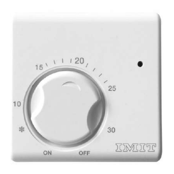
1 = Temperature setting knob ( g. 1) 2 = Warning lamp (TA5-A, TA5-B, TA5-C) 3 = ON/OFF switch (TA5-B) or SUMMER/WINTER switch (TA5-C) FIG. 1 OPTIONAL ACCESSORIES Sub-base tting = cod. 004095 ( g.3) FIG. 3 Special tting for temperature range restrictions or for the temperature lock at a pre-set value. = cod. 000071 ( g.4) -
Page 4: Installation And Wiring Connections
FIG. 4 INSTALLATION PLACEMENT OF THE THERMOSTAT FIG. 6 Install the thermostat away from heat sources (radiators, sunrays, and kitchens) and away from doors/windows, at approx. 1,5 m height from the oor. ( g.6) INSTALLATION AND WIRING CONNECTIONS A) In case the thermostat shall be installed either in a round built-in box (having distance between centres equal to 60mm), or on an uneven wall surface or in other particular locations, it is recommended to use a sub- base tting (see paragraph “Optional Accessories ”). - Page 5 FIG. 7 B) Remove the front cover from the thermostat base by releasing the provided clip ( g.8), then x it to the wall (or to the sub-base tting) through the provided holes ( g.9) and tighten it by means of suitable screws having max of 3,5 mm.
-
Page 6: Turning The Thermostat On And Off
TURNING THE THERMOSTAT ON AND OFF On TA5-B, put the switch onto the “ON” position to start the equipment or onto the “OFF” to turn it off. ( g.12) We use cookies to ensure that we give you the best experience on our website. If you continue to use this site we will assume that you are happy with it. -
Page 7: Temperature Setting
FIG. 12 TEMPERATURE SETTING When the appliance is connected and the electric power is switched on, set the desired room temperature simply by turning the temperature-adjusting knob to the corresponding value on the graduated scale. ( g.11) FIG. 11 TEMPERATURE RANGE RESTRICTION AND TEMPERATURE LOCK WARNING: THE TEMPERATURE RANGE RESTRICTION AND TEMPERATURE LOCK OPERATIONS MUST BE CARRIED... -
Page 8: Temperature Lock
FIG. 8 Insert the provided tting (see paragraph “Optional Accessories ”) in the knob at the desired limit points (min. and max.) according to the corresponding values marked on the knob body. Make sure that the metal retainer remains in its correct position between the min. and max. limit points. ( g.14); Snap the front cover back. FIG. -
Page 9: Problem Solving
FIG. 15 SUMMER/WINTER SWITCH On TA5-C, put the switch onto the position to set up the “summer” operation mode (air conditioning system), or onto the “ ” position to set up the “winter” operation mode (heating system). ( g.13 ” position to set up the “winter”... - Page 10 Air draughts coming from the electrical wires conduit Solution Follow the instructions of paragraph “Placement of the thermostat” Seal the conduit to prevent warm or cold air draughts IMIT CONTROL SYSTEM s.r.l. Via Varallo Pombia,19 Castelletto Sopra Ticino (NO) Tel (+39)0331941600 Fax (+39)0331973100 P.IVA IT02223920063...
Need help?
Do you have a question about the TA5 and is the answer not in the manual?
Questions and answers