
Subscribe to Our Youtube Channel
Related Manuals for SENKO SI-200


Summary of Contents for SENKO SI-200
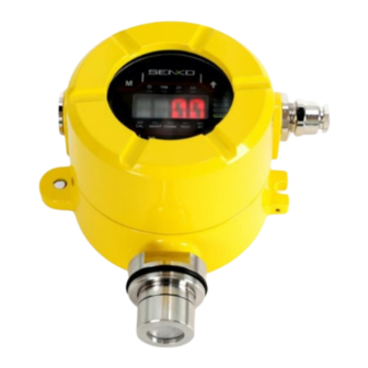
- Page 1 SI-200 Explosion-proof Diffusion Type Gas Detector USER MANUAL SI-200E SI-200A www.senko-detection.com...
-
Page 2: Table Of Contents
SI-200 USER MANUAL CONTENTS 1. Product Overview ....................5 1.1. Introduction ......................5 1.2. Key Feature ....................... 5 1.3. Specification ...................... 5 1.4. Sensor List ......................6 1.5. Outline ....................... 7 2. Appearance and Description ................7 2.1. Component ......................7 2.2. - Page 3 SI-200 USER MANUAL 8. Maintenance ......................30 8.1. Function Gas Test ................... 30 8.2. Detector Operational Life ................30 9. Installation Precautions ..................31 9.1. Selection of installation location..............31 9.2. Selection of installation position..............31 9.3. Caution before installation ................31 9.4.
- Page 4 ➢ Warranty We, SENKO CO., LTD warrant replacement or repair for the products of SI series for 24 months from the shipment date of the product(s). However, the parts, whose life can be shortened by use, such as sensors, batteries and lamps are not under the warranty. Also, free repair and replacement is not available in case of purchases of our products through unauthorized channels, mechanical damage, and deformation by user’s misuse, and calibration and replacements of parts without following the...
-
Page 5: Product Overview
USER MANUAL 1. Product Overview 1.1. Introduction SI-200 was developed to prevent unfortunate accidents caused by gas explosions in hazardous places such as plants, gas storages, and factories. When installed in hazardous area, Toxic gas detector SI- 200 will regularly and continuously detect the gas leakage and display the data with FND and to supply 4-20mA standard output. -
Page 6: Sensor List
SI-200 USER MANUAL 1.4. Sensor List Sensor Range Resolution Oxygen Electrochemical 0~30%Vol 19.0%vol 23.0%vol 0.1%vol 0~500ppm Carbon Monoxide Electrochemical 30ppm 60ppm 1ppm 0~2,000ppm(Option) Sulfur Dioxide Electrochemical 0~20ppm 2ppm 5ppm 0.1ppm Hydrogen Catalytic 0~100%LEL 15%LEL 50%LEL 1%LEL within Hydrogen Electrochemical 0~1000ppm... -
Page 7: Outline
SI-200 USER MANUAL 1.5. Outline 2. Appearance and Description 2.1. Component... - Page 8 SI-200 USER MANUAL NAME DESCRIPTIONS It protects sensors and PCB boards built into the product from external Case cover environmental changes and shocks. Mount Holes It is a Mounting Hole used to fix the product. When setting the gas concentration value and parameter measured by FND display the sensor, the set mode is indicated by numbers and icons.
-
Page 9: Front Display Configuration
SI-200 USER MANUAL 2.2. Front Display Configuration Name Descriptions Power LED(Green) When the power (DC 24V) is supplied normally, the LED flashes after lighting. Trouble LED Displayed when fault detected on gas detector self-diagnosis. Alarm1 LED Displayed when Alarm1 is set or detected. -
Page 10: Bracket Dimensions
SI-200 USER MANUAL 2.3. Bracket Dimensions... -
Page 11: How To Install
SI-200 USER MANUAL 3. How to install CAUTION Installing a detector at a site, opening the cover of a detector, or operating it may cause fire or explosion depending on the environment. Therefore, you should proceed with your work after turning off the power and examining whether explosive residual gas is around you or not. -
Page 12: Power, Rs485, 4-20 Ma Terminal Configuration
SI-200 USER MANUAL 3.2. Power, RS485, 4-20 mA Terminal configuration Loosen the case cover fixed screen on the side of the detector and separate the case cover. Then Terminal appears. 3.2.1. DC Terminal Pin No. Name Description Ground Power The DC terminal consists of a terminal for power supply of the detector. -
Page 13: 4-20Ma Wiring Method Example
SI-200 USER MANUAL 3.2.4. 4-20mA wiring method example 3.3. Alarm Terminal Configuration Connect the Alarm Relay connected to the terminal using the following configuration. 3.3.1. Fault Relay Output Configuration Jumper Setup Terminal Fault Relay Contact Normal Close Mode CON402 Jumper NC on... -
Page 14: Ground Connection Configuration
SI-200 USER MANUAL 3.4. Ground Connection Configuration Internal grounding: You can ground the internal grounding through point 1 using the ring terminal. External grounding: Can ground the external grounding through point 2 using the ring terminal. No two ‘Earth Points’ should be connected via screen or conduit so as to avoid ‘ground loops’.). -
Page 15: Operation
USER MANUAL 4. Operation 4.1. Default Configuration SI-200 are supplied with a default configuration as shown below. The settings for full scale range, calibration gas level, calibration interval, access password can be changed to suit individual applications. 4.2. Power On... -
Page 16: Measure Mode
SI-200 USER MANUAL 4.3. Measure Mode Alarm LED ▶Power/Trouble/Alarm 1/Alarm2 Current gas concentration display Gas concentration unit display ▶Changing a decimal point based on the range Status LED ▶CAL: Calibration in progress ▶MAINT: Maintenance in progress ▶COMM: Communication status ▶TEST: Test in progress ▶BR: Bluetooth connection status... -
Page 17: System Mode
SI-200 USER MANUAL 5. System Mode 5.1. Mode Configuration The device consists of the following menu configuration. Division Mark Definition Note CONFIGURATION Basic setting MEASUREMENT MEAS Measurement setting CALIBRATION Calibration setting ALARM Alarm setting TEST TEST Test Engineering Mode TIME... -
Page 18: Setting / Configuration Munu
SI-200 USER MANUAL 1 Depth 2 Depth 3 Depth Default Decimal point DECP(Decimal Point) 100.0 (1000, 100.0, 10.00, 1.000) MEAS F-RN Full measuring range (1~9999) 500.0 (Measurement) (Full Range 1~9999) Measuring unit UNIT (PPB, PPM, VOL%, %LEL) ZERO (Zero Calibration) - Page 19 SI-200 USER MANUAL HART Option ▶ Press the Select Key, you can check whether including HART option. Change BAUD rate ▶Press the Select Key to get into the change option. ▶Select 1200 / 9600 / 19.2K / 38.4K with the Up / Down Key, and press the select key.
- Page 20 SI-200 USER MANUAL Change Password ▶Press the Select Key to get into the change option. ▶Select from 0 to 99 with the Up/Down Key, and press the Select Key. Change Calibration Period ▶Press the Select Key to get into the change option.
- Page 21 SI-200 USER MANUAL Change Brightness ▶Press the Select Key to get into the change option. ▶Select from 1 to 15 with the Up/Down Key, and press the Select Key. Device version Sensor cartridge version BLE MAC ADDRESS...
-
Page 22: Setting / Measurement Munu
SI-200 USER MANUAL 5.4. Setting / Measurement Menu You can change the detection settings list with the Up/Down key. DECP/F-RN/UNIT Change Decimal Point ▶Press the Select Key to get into the change option. ▶Select from 1.000 to 1000 with the Up / Down Key, and press the select key. -
Page 23: Setting / Calibration Menu
SI-200 USER MANUAL 5.5. Setting / Calibration Menu You can change the calibration settings list with the Up/Down key. ZERO/S-CN/SPAN Zero Calibration ▶Press the Select Key to get into the change option. ▶Value indicates by a blink in the screen. -
Page 24: Setting / Alarm Menu
SI-200 USER MANUAL 5.6. Setting / Alarm Menu You can change the alarm settings list with the Up/Down key. LACH/ENER/DLY/ALM1/ALM2 Change Alarm Latch ▶Press the Select Key to get into the change option. ▶Select between on and off with the Up/Down Key, and press the Select Key. - Page 25 SI-200 USER MANUAL Change Alarm 1 Level ▶Press the Select Key to get into the change option. ▶Select from 1 to 9999 with the Up/Down Key, and press the Select Key. Change Alarm 1 Level ▶Press the Select Key to get into the change option.
-
Page 26: Problem Solving
SI-200 USER MANUAL 6. Problem Solving 6.1. Error Code Ex) Error Display Code code code Cause Solution Code Code When Firmware Version is abnormal Update the Firmware The abnormal data of Firmware Tag Update the Firmware The abnormal data of Firmware CRC... -
Page 27: Interface Configuration
SI-200 USER MANUAL 7. Interface Configuration 7.1. RS485 Interface Setting Baud rate: 9600 bps Data Format: RTU Data bits: 8bits Stop bit: 1bits Parity: None For more information, please visit: www.modbus.org 7.2. Modbus RS485 / TCP Register 7.2.1. -
Page 28: 4000X Register Read
SI-200 USER MANUAL 7.2.2. 4000X Register Read Sortation Address Bits Description 0: Warmup 1: Measure Mode 2: Inhibit Alarm 3: Inhibit Alarm/Fault BIT0~3 4: Inhibit Full 5: Reserved 6: Test Mode 7: 4-20mA Calibration Mode 9-15: Reserved BIT4 Fault Active Status... - Page 29 SI-200 USER MANUAL Temperature Measured value of the temperature 40008 BIT0~15 measurement (Signed 16bit Integer) 40009 BIT0~15 Current Time Stamp (Upper 2byte) Time Stamp 40010 BIT0~15 Current Time Stamp (Lower 2byte) Heartbeat 40012 BIT0~15 Detector Heartbeat Real number Alarm 1 set value...
-
Page 30: 4000X Register Write
SI-200 USER MANUAL 7.2.3. 4000X Register Write Sortation Address Bits Description 40013 BIT0~15 Real number Alarm 1 set value (Upper 2 bytes) Alarm 1 set value (Real number) 40014 BIT0~15 Real number Alarm 1 set value (Lower 2 bytes) 40015... - Page 31 SI-200 USER MANUAL 9. Installation Precautions 9.1. Selection of installation location The places where gas detectors should be installed in accordance with the occupational safety and health act are as follows. Around chemical facilities and auxiliary facilities that are feared to leak gas, such as ...
- Page 32 IEC 60079-11:2011 Revised History Clause Content Document NO. Revision Revised Date First written 1862SI-200B1020-D200 Rev 1.0 2022.06.14 Update Content Update Rev 2.0 2024.04.16 T : +82-31-492-0445 F : +82-31-492-0446 sales@senko.co.kr www.senko-detection.com 445, Doksanseong-ro, Osan-si, Gyeonggi-do, Republic of Korea...
- Page 33 SI-200 USER MANUAL...
Need help?
Do you have a question about the SI-200 and is the answer not in the manual?
Questions and answers