Table of Contents
Advertisement
Advertisement
Table of Contents

Related Manuals for SENKO SI-100


Summary of Contents for SENKO SI-100
- Page 1 MODEL: SI-100 (Fixed Gas Detector) Manual...
- Page 2 In this case, all the expenses except freight cost are paid by SENKO. Repair, replacement and freight cost for the products, whose warranty is already over, are paid by the user. SENKO CO., LTD does not have any responsibility for indirect, or accidental loss which occurs while using our products, and the warranty is limited to the exchange of parts and products.
-
Page 3: Table Of Contents
SI-100 MANUAL Table of Contents Introduction ..................................4 1.1. Specification ................................4 1.2. Sensor List ................................5 Instrument Overview ..............................6 How to install ..................................7 3.1. How to fix................................7 3.2. How to open and wire ............................ 7 3.2.1 Separating Cover from Gas Detector Body .................. -
Page 4: Introduction
SI-100 MANUAL Introduction 1.1. Specification Various sensors can be applied ✓ Easy operation with a magnetic bar ✓ Large digital LCD embedding white backlight ✓ Explosion-proof & Water/Dust-proof structure ✓ Automatic calibration function ✓ Long-distance transmission by 4-20mA output ✓... -
Page 5: Sensor List
SI-100 MANUAL 1.2. Sensor List Sensor Range Resolution Oxygen Electrochemical 0~30%Vol 19.0%vol 23.0%vol 0.1%vol Carbon Monoxide Electrochemical 0~500ppm 30ppm 60ppm 1ppm Sulfur Dioxide Electrochemical 0~20ppm 2ppm 5ppm 0.1ppm Hydrogen Catalytic 0~100%LEL 15%LEL 50%LEL 1%LEL Hydrogen Electrochemical 0~1000ppm 100ppm 500ppm within 5ppm... -
Page 6: Instrument Overview
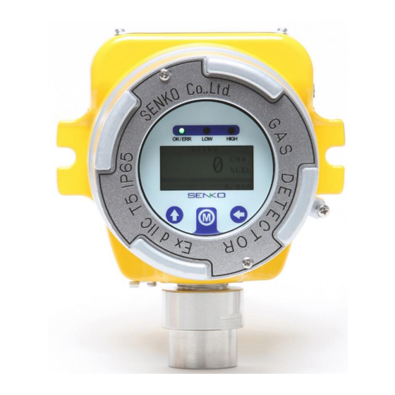
SI-100 MANUAL Instrument Overview 1. OK/ERR LED (Power & Operation) 2. LOW Alarm (1 alarm) 3. HIGH Alarm (2 alarm) 4. Sensor Housing and Sensor Part 5. Buttons (Use a Magnetic bar) -
Page 7: How To Install
SI-100 MANUAL How to install Installing a detector at a site, opening the cover of a detector, or operating it may cause fire or explosion depending on the environment. Therefore, you should proceed with your work after turning off the power and examining whether explosive residual gas is around you or not. -
Page 8: Gas Detector Wiring Diagram
SI-100 MANUAL 3.2.2 Gas Detector Wiring Diagram DC 24V 4~20 mA Contact output in LOW alarm (DRY or DC 24V) Contact output in HIGH alarm (DRY or DC 24V) RS 485+ Telecommunication output Normal : Dry LOW : DRY LOW : 24V... -
Page 9: Measuring Mode
When it is impossible for the detector to initiate measuring mode even when the connection to the sensors is proper, the gas detector should require checks and repairs. Therefore, please contact SENKO CO., LTD or your supplier. Gas Sensor Connection Pin... -
Page 10: Initial Screen Explanation
SI-100 MANUAL 4.1.1 Initial Screen Explanation Model Concentration Gas Type Unit Bar graph (concentration) 4-20mA 4.2. Set Display The displays are sequentially shown whenever you press each mode key ( ) by using a magnetic bar. 4.2.1 Description of Set Display... -
Page 11: Advanced Setting
SI-100 MANUAL 4.3. Advanced setting PUSH (2s) PUSH (2s) PUSH (2s) Press MODE key ( ) for 2 seconds by using the magnetic bar in Set Display to enter Advanced ➢ setting. Press MODE key ( ) by using the magnetic bar in Advanced setting screen, in order to go to ➢... -
Page 12: How To Modify The Settings [Flow Chart]
SI-100 MANUAL 4.4. How to modify the settings [Flow chart] “2sec” Blinking Blinking “2sec” “1sec” Blinking Blinking Blinking Blinking Blinking “2sec” “1sec” Press MODE key ( ) for 2 seconds by using the magnetic bar in Set Display, in order to enter ➢... -
Page 13: Zero Calibration & Span Calibration
4.5.1 How to connect Calibration cap Correctly attach the calibration cap to the sensor part of the gas detector (SI-100) as the picture ➢ above (using flow meter, etc., flow rate: about 300 SCCM) and inject the calibration gas. -
Page 14: How To Enter Calibration Mode
SI-100 MANUAL 4.5.3 How to enter Calibration Mode Press MODE key ( ) 4 times by using the magnetic bar in Measuring mode, in order to enter ➢ Calibration mode. Press MODE key ( ) for 2 seconds by using the magnetic bar in Calibration mode, in order to ➢... -
Page 15: Certificate
SI-100 MANUAL Certificate... - Page 16 SI-100 MANUAL...
Need help?
Do you have a question about the SI-100 and is the answer not in the manual?
Questions and answers