Table of Contents
Advertisement
Available languages
Available languages
Quick Links
ACS-10型气体密度测量仪表校准系统
Calibration system for gas density instrumentation,
model ACS-10
Kalibriersystem für Gasdichteinstrumentierung,
Typ ACS-10
Système d'étalonnage pour instruments de mesure de
la densité de gaz, type ACS-10
Sistema de calibración para instrumentos de medición
de densidad de gas, modelo ACS-10
Calibration system for gas density measuring instruments
操作说明
Operating instructions
Betriebsanleitung
Mode d'emploi
Manual de instrucciones
CN
EN
DE
FR
ES
Advertisement
Chapters
Table of Contents

Subscribe to Our Youtube Channel
Related Manuals for WIKA ACS-10


Summary of Contents for WIKA ACS-10
- Page 1 ACS-10 Kalibriersystem für Gasdichteinstrumentierung, Typ ACS-10 Système d'étalonnage pour instruments de mesure de la densité de gaz, type ACS-10 Sistema de calibración para instrumentos de medición de densidad de gas, modelo ACS-10 Calibration system for gas density measuring instruments...
- Page 2 Mode d‘emploi type ACS-10 Page 163 - 216 Manual de instrucciones modelo ACS-10 Página 217 - 270 © 10/2021 WIKA Alexander Wiegand SE & Co. KG All rights reserved. / Alle Rechte vorbehalten. WIKA is a registered trademark in various countries. ®...
-
Page 3: Table Of Contents
5 调试和运行 5.1 ACS-10用户界面......17 5.2 按钮说明 ......18 5.3 充气... - Page 4 8.2 返修 ......47 8.3 废弃处理 ......48 9 规格 10 附件 附件:欧盟符合性声明 威卡操作说明,ACS-10型校准系统...
-
Page 5: 缩写和定义
本操作说明属于产品的一部分,应随仪表放置,便于技术人员随时查阅。将本操作说 明转交下一位仪表操作人员或所有者。 ■ 开始操作前,技术人员必须仔细阅读并理解操作说明。 ■ 如果操作说明的翻译版本和英文版本给出了不同的解释,应以英文版本为准。 ■ 为了提高文本的可读性,我们使用通用的人称代词“他”。我们应明确了解到,这也代 指女性和其他性别人士。 ■ 除了本操作说明外,所提供的供应商文件(如有)也被视为产品的一部分。 ■ 销售文件中包含的一般条款和条件应适用。 ■ 我们保留技术修改之权利。 ■ 更多信息: -网址: www.wika.cn / www.wika.com -相关数据资料: SP 60.15 -联系方式: 电话:(+86) 400 9289600 缩写和定义 ■ 项目符号 ▶ 说明 1..x. 按步骤操作 ⇒ 说明的结果 威卡操作说明,ACS-10型校准系统... -
Page 6: 一般安全指令
1 一般信息 / 2 安全 符号说明 警告! ……用于警示潜在的危险情形,若不避免,可能会导致严重的人身伤害 或死亡。 注意! ……用于警示潜在的危险情形,若不避免,可能导致人员轻伤或财产、 环境损害。 危险! ……确定由电气系统导致的危险。如果未遵守安全指示,可能引发严重 或致命的伤害。 警告! ……用于警示潜在的危险情形,若不避免,可能会因高温表面或液体导 致灼伤。 信息 ……给出有用的提示、建议和信息以进行高效的无故障操作。 2 安全 一般安全指令 在使用仪表前,需确保所有连接件(ACS-10和气瓶之间、ACS-10和测试对象之间以 ■ 及ACS-10和气体室之间)充分密封。 确保始终使用为此目的设计的气体(通常为SF 气体)或正确的混合气体(例如SF₆/ ■ CF₄)对测试对象进行重新校准。 在仪表的运行过程中,必须保持正确的市电电源和规定的环境条件(尤其不能在雨中 ■ 操作)。 在用ACS-10测试泄漏检测系统之前,必须确定气室的气体质量(例如,通过使用威 ■ 卡的GA11型分析仪表)。这是确保大量SF₆气体分解产物不会被吸收到ACS-10中的 唯一方法。 充气时(例如,使用外部气瓶),接头2处的最大连接压力不得超过1 MPa绝压。可 ■ 从威卡选购相应的减压器。 测试对象接头1处的最大连接压力不得超过1.6 MPa绝压。... -
Page 7: 预期用途
2 安全 预期用途 作为SF₆密度测量仪表校准系统的ACS-10,设计用于SF₆气体或替代绝缘气体的密度测 量。该仪表可在室外或室内工业环境中用于电气装置以及电气装置安装调试的验收。 使用仪表前,必须遵守规定的限值,并进行气体分析。 该仪表不得用于危险区域! 仪表仅为此处所述的预期用途设计和制造,且只能按照说明进行使用。 用户必须遵守操作说明中包含的技术条件,参见章节9 “规格”。假设仪表操作正确, 并且符合其技术规格。否则,应立即停止使用仪表,并由授权的威卡服务工程师对其进 行检查。 使用电子精密测量仪表时应特别小心(避免潮湿、撞击、强磁场、静电和极端温度, 不得将任何物体插入仪表或其开口处)。必须保护接头和内螺纹接头免受污染。 如未遵守预期用途进行操作,制造商将不承担任何责任。 不当使用 注意! 超出性能限制带来的人身伤害 超出性能限制范围可能损坏仪表并导致在终端应用中发生危险。 使用仪表的应用条件必须在技术性能限制范围内,参见章节 “规格”。 ▶ 即使在终端应用中发生故障,也绝不能超过过载限制。超过过载限值 的负载可能导致不可逆的损害。 ▶ 产品所使用机器或设施的制造商或运营商必须确保接液部件材质与所 用介质的相容性。 任何超出或不同于预期用途的使用均被视为不当使用。 ■ 未经授权不得擅自对仪表进行修改。 ■ 仅使用原装配件。采用未经批准的零件被视为使用不当。 ■ 请勿在安全装置或紧急关闭装置中使用该仪表。 ■ 人员资质 本操作说明中所描述的作业仅可由具备以下资质的技术人员进行操作。 威卡操作说明,ACS-10型校准系统... -
Page 8: 个人防护设备
2 安全 技术人员 经营者授权的技术人员是指经过技术培训、理解测控技术知识,并结合自身经验,依据 相关国家法规、现行标准和指令而进行下列作业,并可独立识别潜在危险的人员。 用户必须具备足够的资质,按照以下规定进行检查和维护工作: 温室氟化气体法规(EU)2024/573 ■ 欧盟实施条例(EU)2015/2066 ■ 特殊运行条件下,操作人员需要进一步了解相关知识,如危险介质。 2 5 个人防护设备 个人防护设备旨在保护技术人员在作业期间免受可能损害其安全或健康的危险。在仪表 上操作和使用仪表作业时,技术人员必须穿戴个人防护设备。 使用仪表时,建议穿戴下列防护设备。 请穿戴护目镜 保护眼睛免受飞溅颗粒和液体的伤害。 请穿戴防护手套 保护手免受摩擦、擦伤、割伤或重伤,并避免接触热表面和危险介质。 请穿安全鞋 保护双脚免受坠落物体或周围物体的伤害,以及有毒或有害液体和危险 介质造成的伤害。 开关设备使用安全说明 警告! 有害介质造成的人身伤害 仪表及其部件上的残留介质可能对人员、环境和设备造成危险。 ▶ 请采取充分的预防措施。 ▶ 发生故障时可能出现腐蚀性介质。 设施运营商必须确保仅由合格的公司或经过IEC 62271-4或IEC 60480第10.3.1节培训的 合格人员来处理SF₆气体。 威卡操作说明,ACS-10型校准系统... - Page 9 BGI 753(德国SF₆工厂和设备) ■ IEC 62271-4(SF₆气体处理) ■ IEC 60376(新SF₆气体,工业级SF₆气体) ■ IEC 60480(用过的SF₆气体) ■ CIGRE报告276, 2005(SF₆操作实践指南) ■ 运行中的泄漏: IEC 60376(新SF₆气体,工业级SF₆气体) ■ IEC 60480(用过的SF₆气体) ■ CIGRE 2002(“电气工业中的SF₆气体”) ■ 维修和维护: IEC 62271-4(高压开关设备和控制设备中的SF₆气体使用和处理) ■ CIGRE 1991(SF₆气体处理) ■ CIGRE报告276, 2005(SF₆操作实践指南) ■ SF₆气体是一种无色无味、化学中性、惰性和不可燃气体,比空气重约五 倍,无毒且对臭氧层无害。详情见IEC 60376和IEC 62271-4。 威卡操作说明,ACS-10型校准系统...
-
Page 10: 标签和安全标志
2 安全 标签和安全标志 必须保持标签和安全标志清晰可见。 产品标签(示例) WIKA Alexander Wiegand SE & Co. KG Alexander-Wiegand-Straße 30, D-63911 Klingenberg 型号 序列号 产品编号 最大输入压力 供电电源 工作温度 最大功耗 生产日期 符号 开始安装和调试仪表之前,确保您已阅读操作说明。 请勿与生活垃圾一起丢弃请确保按照国家规定妥善处理。 威卡操作说明,ACS-10型校准系统... -
Page 11: 包装和储存
[29.00 psi] 罐,参见章节5.12 绝压,即可运输仪表。当显示“可运输”符号时,这意味着仪表中的内部压 力为≤ 0.2 MPa[29.00 psi]绝压,可以进行运输。 请检查仪表是否产生任何损坏。 如发现任何损坏,请勿调试仪表,应立即联系制造商。 如果将仪表从低温环境运输到高温环境,可能会形成冷凝水导致仪表故障。在重新调试 之前,请先等待仪表温度恢复到室温。 3 2 包装和储存 警告! 危险介质可能会造成人身伤害、财产损失和环境破坏 仪表中的残留介质会对人员、环境和设备造成危害。 ▶ 在存放仪表之前(操作之后),请清除所有残留介质并冲洗仪表。 尤其是对健康有害的介质, 例如腐蚀性介质、有毒介质、致癌介质、 放射性介质等,这一点尤为重要。 安装(操作)之前请勿拆除包装。 请保留包装,以便在运输过程中(如更换使用地点、送修等)为仪表提供最佳保护。 储存场所的允许条件: 储存温度:-10 ... +60 °C [14 ... 140 °F] ■ 湿度:10 ... 90%相对湿度(无冷凝) ■ 威卡操作说明,ACS-10型校准系统... - Page 12 3 运输、包装和储存 避免暴露于以下条件: ■ 阳光直射或靠近高温物体 ■ 机械振动和机械冲击(重摔) ■ 油烟、蒸汽、粉尘和腐蚀性气体 ■ 危险环境、易燃环境 ■ 仪表或电源装置处的水分(湿气、雨水) 请将仪表连带原包装存放在满足上述条件的位置。在储存前,必须对已经使用的仪表进 行清洁,参见章节7.2 “清洁”。 如果原包装不可用,请按照下述方法包装和储存仪表: 1. 请使用防静电塑料薄膜包裹仪表。(适用于带电气组件的仪表) 2. 请将仪表和减振材料一起放入包装内。 3. 如果存放时间较长(30天以上),请在包装内放置干燥包。 威卡操作说明,ACS-10型校准系统...
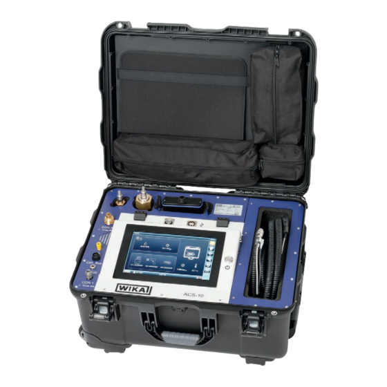
- Page 13 4 设计和功能 4. 设计和功能 概览 接头1:测试对象的压力连接接口 Pt100温度计的连接接口 连接套件的连接接口 接地连接 接头2:用于充气和排空仪表的连接接口 DN8和DN20联结器接口 电源连接接口 连接套件的存放处 用于导出文件的USB接口 产品标签 软管套装和气体密度表的连接电缆的存放处 RS-232打印机接口 开启和关闭开关 威卡操作说明,ACS-10型校准系统...
-
Page 14: 供货范围
4 设计和功能 供货范围 主箱 ■ 仪表ACS-10 ■ 连接套件 ■ 适配器DN8内螺纹至快速接头 ■ 适配器DN20内螺纹至快速接头 软管套装4 m [13.12 ft] ■ ■ 用于气体密度表和开关的16芯连接电缆,最多可用于5个转换开关电接点 ■ 带转换接头的电源装置,适用于美国、中国和英国 ■ 订购的附件 ■ 操作说明 可选配件箱 配备附件中的所有组件。 请按交货单核对供货范围。 描述 通过使用SF₆密度测量仪表(ACS-10)的校准系统,合格人员可以重新校准气体密度测 量仪表,例如在现场作为接收检查的一部分,或在电气系统调试期间进行校准。重新校 准通常指泄漏检测系统的功能检查。 ACS-10可通过集成的压缩机向泄漏检测系统加压,并随后缓慢释放压力。同时,还可 测量机械开关的开关精度、回差和接触电阻。 从而确保气体密度测量仪表正常工作,并满足使用者的预期要求。 ACS-10配有一个集成气体储存容器和一个压缩机。利用这些元件和高精度的压力和温 度测量传感器,校准系统可作为重新校准的参考仪表。本装置可对带有最多5个转转换 开关电接点的常规气体密度表和气体密度开关,以及气体密度指示器进行功能测试。 威卡操作说明,ACS-10型校准系统... - Page 15 ▶ 必须遵守数据资料中的环境条件。 警告! 危险介质可能会造成人身伤害、财产损失和环境破坏 接触危险介质(如氧气、乙炔、易燃或有毒物质)、有害介质(如腐蚀 性、毒性、致癌性、放射性物质)时,有造成人身伤害、财产损失和环 境破坏的危险。 如发生故障,危险介质可能会附着在仪表上或从仪表中逸出。 ▶ 对于这些介质,除所有标准规定外,还必须遵守相应的现行法规或 规定。 请穿戴必要的防护设备,参见章节 2.5 “个人防护设备”。 警告! 危险介质可能会造成人身伤害、财产损失和环境破坏 接触危险介质(如氧气、乙炔、易燃或有毒物质)、有害介质(如腐蚀 性、毒性、致癌性、放射性物质)时,有造成人身伤害、财产损失和环 境破坏的危险。 如发生故障,仪表上可能存在极高温状态(超过55°C [131°F])的危险 介质。 ▶ 对于这些介质,除所有标准规定外,还必须遵守相应的现行法规或 规定。 请穿戴必要的防护设备,参见章节2.5 “个人防护设备”。 警告! 危险介质可能会造成人身伤害、财产损失和环境破坏 接触危险介质(如氧气、乙炔、易燃或有毒物质)、有害介质(如腐蚀 性、毒性、致癌性、放射性物质)时,有造成人身伤害、财产损失和环 境破坏的危险。 如发生故障,仪表上可能存在高压或真空状态的危险介质。 ▶ 对于这些介质,除所有标准规定外,还必须遵守相应的现行法规或 规定。 请穿戴必要的防护设备,参见章节 2.5 “个人防护设备”。 威卡操作说明,ACS-10型校准系统...
- Page 16 5 调试和运行 注意! 仪表坠落造成的人身伤害 如仪表坠落,可能会导致肢体挫伤。 ▶ ACS-10在运行期间必须在水平和牢固表面上处于水平位置。 仅可使用原装部件,参见章节10 “附件”。 请检查仪表是否产生任何损坏。 如发现任何损坏,请勿调试仪表,应立即联系制造商。 供电电源要求 请遵守产品标签上对供电电源的规定。 开启仪表 在开启仪表之前,通过自动校准系统和客户开关设备之间的接地连接建立等电位连接, 以避免因电位差而放电。 1. 把电源插头接到电源上。 2.将另一端连接到仪表的电源连接器上。 3.用手指按On/Off(开/关)开关以开启。 ⇒ 仪表已打开 ⇒ 控制面板已启用 威卡操作说明,ACS-10型校准系统...
-
Page 17: Acs-10用户界面
5 调试和运行 5 1 ACS-10用户界面 主屏幕 主屏幕显示组件(1、2、16)是否已连接。此外,还显示内部气体容器中的当前压力和 内部温度(14和15)。 可通过点击菜单按钮(5~10)在菜单项之间切换。 运输符号说明仪表在其当前状态下是否可以运输。仅当仪表中的内部压力为 ≤ 0.2 MPa [29.00 psi]绝压时, 才可以进行运输。 建议为每个用户创建单独的用户配置文件。活跃用户配置文件显示在主频幕(17)上。 打印机状态 示意图 扫描仪状态 连接套件的状态 环境空气湿度 运输状态 U盘已插入 环境压力 主屏幕 箱子中的温度 数据管理 内部气体储存容器中的压力 测试模式... -
Page 18: 按钮说明
5 调试和运行 按钮说明 所有菜单和子菜单的下述各按钮功能相同。 按钮 功能 创建新条目 选择所有条目 取消选择所有条目 搜索字段以筛选显示的结果 打印条目(打印机作为可选配件提供) 清除条目 将条目导出到外部数据载体 从外部数据载体导入条目 转到上一菜单 威卡操作说明,ACS-10型校准系统... - Page 19 5 调试和运行 充气 警告! 因接触分解产物而造成的身体伤害 如果充气过程中没有使用新技术级气体,操作人员可能会接触分解产物。 ▶ 仅向ACS-10填充新技术级气体。 警告! 超压爆炸造成的人身伤害 错误条目(例如,测试压力过高)可能导致超压爆炸,从而造成严重的 人身伤害。 ▶ 仅设置允许的测试参数。 注意! 危险介质可能会造成人身伤害、财产损失和环境破坏 充气不当可能导致气体逸出。 ▶ ACS-10只能通过接头2进行充气。 ▶ 充气期间不得连接任何测试对象。 注意! 人身伤害和财产损失 MPa[145.03 psi]绝压。 将外部气瓶连接到接头2时,应确保压力不超过1 否则,这可能会对人员、环境和设备造成风险,并破坏校准系统。 ▶ MPa[130.53 psi]绝压。 向内部储气罐充气时,最大压力不超过0.9 注意! 仪表坠落造成的人身伤害 充气不当可能导致仪表掉落,从而导致肢体挫伤。 ▶ ft]的软管进行充气。 使用最大长度为4米[13.12 ▶ ACS-10在水平和稳固的表面上充气时必须处于水平位置。 调试必须在水平位置的水平稳定表面上进行。仅允许使用新技术级气体进行填充。...
- Page 20 5 调试和运行 MPa[145.03 psi]绝压的减 在将ACS-10连接到外部气瓶之前,必须首先连接一个p 压器。 ACS-10的填充只能在有SF₆气体监测的房间内或室外进行(例如,使用SF₆气体传感器, 限值1,000 ppm (温室氟化气体法规2024/573或国家特定法规)。 充气过程中不得连接任何测试对象。 在进行充气时,在“服务”菜单中输入目标压力,然后点击“开始充气”按钮(1)。随 后,ACS-10将显示必要的步骤,并开始充气过程,直到达到指定的目标压力。 威卡操作说明,ACS-10型校准系统...
-
Page 21: 创建新的测量位置
5 调试和运行 5 4 创建新的测量位置 通过点击菜单项“数据”下面的按钮“设备列表”(1),创建新的测量位置。 或者,可以从“模板目录”(2)中选择威卡SF₆泄漏检测系统(例如GDM-100)作为模 板。 可以在“数据管理”的“设备列表”中添加一个新的测量位置(1)。 威卡操作说明,ACS-10型校准系统... - Page 22 5 调试和运行 可为新测量位置和测试对象指定单独名称(1)。必须注意使用正确的单位(3),并考 虑使用参考等容线(4)。可在“设备类型”(2)下选择待测试仪表的类别。 威卡操作说明,ACS-10型校准系统...
- Page 23 5 调试和运行 威卡的泄漏检测系统可选择以下型号: 威卡型号概览 GDM-100型 ■ 带开关的气体密度表 GDM-RC-100型 ■ GDS-RC-HV型 ■ 气体密度开关 GDS-HV型 ■ GDI型 ■ 气体密度显示器 测量时可考虑或忽略标定压力的参考等容线。由于温度补偿式气体密度表始终校准至特 定压力(通常为第一个开关动作点的压力),因此强烈建议将参考等容线纳入考虑! 在考虑使用参考等容线,必须输入校准压力(5)。校准压力通常标记在仪表上(例如 Pcal、Pc或类似产品)。 通常,基于波登管压力计的气体密度表(如GDM-100型)具有相对精度,基于波纹管系 统的气体密度表(如GDM-RC-100型)具有绝对精度。 必须注意输入正确的测量范围(1),尤其是对于具有精度等级(例如GDM-100型为 1级)的仪表。 这一点很重要,因为相对精度(例如2.5%)总是指满标度值(例如1 MPa绝压 [145.03 psi])(3)。 kPa[3.62 psi]。精度参数(4)的表 在此示例中,重新校准期间的绝对偏差不得超过±25 达形式可以从百分比更改为绝对值。 威卡操作说明,ACS-10型校准系统...
- Page 24 5 调试和运行 ACS-10还设计用于监测替代混合气体的气体密度表。通常,SF₆气体在用作绝缘气体时 为100%。也可以选择其他气体混合物(2)。 每个泄漏检测系统最多可配置5个具有单独名称的开关动作点。 对于每个带有开关触点的泄漏检测系统,必须单独输入开关动作点。可通过点击开关 (2)来激活。 在进行配置时,必须注意将开关设置为减压状态。 在所示示例中,SP1和SP2将在电气系统的额定压力下打开,并在压力降至开关阈值 (5)以下时切换(“下降闭合”)。SP3将在额定压力下断开,在超过开关阈值时将切换 (“上升闭合”)(4)。 开关动作点(3)的名称可以更改。指定所有相关数据后,可保存该泄漏检测系统(1)。 威卡操作说明,ACS-10型校准系统...
- Page 25 5 调试和运行 切换功能示例 以下示例说明,必须为各个开关功能选择泄漏检测系统的电子开关配置。“下降”和“上升” 意指相对于电气设备的额定压力而言。转换开关电接点(如GDM-RC-100型)必须配置 为常开或常闭触点。 注意! 因开关方向错误造成的财产损失 选择错误的切换方向或切换功能会导致使用错误的测试参数进行校准, 从而影响仪表特性。 ▶ 确保指示正确的开关方向(下降/上升)和开关功能(常闭/常开)。 威卡操作说明,ACS-10型校准系统...
-
Page 26: 检查测量位置
5 调试和运行 开关功能 Falling making Falling breaking Rising making Rising breaking 检查测量位置 点击按钮“设备列表”(1),可通过菜单项“数据”查看现有测量位置。 威卡操作说明,ACS-10型校准系统... - Page 27 5 调试和运行 点击测量位置(1)可打开详细视图。 详细视图显示了测试对象的存储参数和此前测量结果。 威卡操作说明,ACS-10型校准系统...
-
Page 28: 对气体密度表或气体密度开关进行重新校准
5 调试和运行 对气体密度表或气体密度开关进行重新校准 可通过菜单项“测试”执行重新校准。 以下仪表可用于测量: ■ 先前通过“来自列表”配置的泄漏检测系统。 尚未通过“快速测试”创建的仪表,参见章节5.4 “创建新的测量位置”。 ■ 使用“来自模板”从威卡组合中预选泄漏检测系统,参见章节5.4 “创建新的测量位 ■ 置”。 选择或配置所需仪表后,可通过点击绿色的“测试设备”或“启动”按钮启动测量。 测试组件显示在屏幕上。 将气体密度表与软管套装连接。连接时,必须确保正确的密封性。为此,请遵守有关机 械装配组件的,参见章节5.7 “机械安装”。将压力软管的另一端插入接头1,将温度探 头插入Pt100接头。 使用GDM-100型或GDM-RC-100型气体密度表(如图所示)和预焊接GLTC-VC型再校 准阀,威卡可在现场重新校准气体密度表,而无需事先拆卸,这意味着相关设施无需 停运。 再校准阀也可作为现场已安装的气体密度表的改装解决方案,并可安装在电气系统和气 体密度表之间。这意味着将来也可以在不拆卸的情况下进行功能测试。 威卡操作说明,ACS-10型校准系统... -
Page 29: 机械安装
5 调试和运行 5 7 机械安装 注意! 锋利的螺纹造成的身体伤害 由于螺纹边缘锋利(例如DN8连接处),可能会出现割伤。 ▶ 请穿戴必要的防护设备。 5.7.1 安装点的要求 扳手对边 安装点必须满足以下条件: ■ 密封面干净无损坏。 ■ 足够的空间用于安全的电气安装。 允许的环境温度且介质温度保持在性能限值内,参见章节9 “规格”。 ■ 测量仪表必须按照EN 837-1安装在常规安装位置,各侧面的最大允许倾斜度为5°。 注意! 部件坠落造成的人身伤害 连接测量适配器时,存在可能掉落的风险,从而导致肢体挫伤。 ▶ 请穿戴必要的防护设备。 ▶ 确保人员或敏感物体不会被击中。 测量位置应优先直接定位在气室处。在测量线的末端进行测量不利于获 得最佳结果(同主腔体的非期望的温差)。 威卡操作说明,ACS-10型校准系统... -
Page 30: 安装仪表
5 调试和运行 5.7.2 安装仪表 最大扭矩根据安装点而定,且必须得到遵守(如材料和形状)。如有任 何疑问,请与应用顾问联系。 有关联系方式,请参见章节1 “一般信息”或操作说明的底页。 扳手对边 1. 封住密封面(→ 参见“密封方式”)。 用手将测试对象拧入软管套装的对应适配器中。 使用卡口扭矩扳手拧紧。 密封方式 直螺纹 使用平垫圈、透镜式密封环或威卡成型密封件对 密封面进行密封。 符合ISO 1179-2 符合EN 837 (原DIN 3852-E) 锥形螺纹 用密封材料(如PTFE胶带)缠绕螺纹。 NPT、R和PT 由于SF₆的高密度,在测量过程中必须考虑校准箱和安装的泄漏检测系统之间的高度差。 必须使用可选高度表来确定箱体和测试对象之间的高度差。然后在“高度差”(1)字段中 输入高度差。 输入的测试对象的实际温度和校准箱与测试对象之间的实际高度差(1)越准确,重新 校准过程就越精确和有意义。 威卡操作说明,ACS-10型校准系统... -
Page 31: 电气安装
5 调试和运行 电气安装 警告! 电压会造成人身伤害和财产损失 校准连接到电气系统的测试对象可能会导致人身伤害和仪表损坏。 ▶ 每个测试对象必须与电气系统断开。 ▶ 这是确保仅将被动测试对象连接到校准系统的唯一方法。 ACS-10可通过多达5个开关触点重新校准气体密度表。对于这些触点中的每一个,在拼 接头中都有两对捆扎绞线。 若要校准少于五个触点的泄漏检测系统,请使用封闭端子固定未连接的线路。为此,在 一个端子中连接一对绞线(如5A和5B)。否则,测量可能错误。 开关触点必须电气隔离,否则可能会出现开关动作点或电阻测量结果不正确的情况。必 须单独测试电耦合触点。 首先将触点拧到测试对象上,然后将接头插入连接套件。 威卡操作说明,ACS-10型校准系统... -
Page 32: Gdm-100型
5 调试和运行 绞线对标记如下: 数字(1到5)表示触点,字母(A,B)表示功能。 A = 测量线 +(电源,直流24 V) B = 测量线 -(触点返回线) 5 8 1 GDM-100型 除了在就地控制柜(LCC)或继电器外壳上进行测试外,还可以直接在密度表的电缆插 座上进行测试。 GDM-100型有两种常见的电缆插座设计。 使用螺纹接头的电缆插座,可直接连接测试套件的电线。 对于连接器版本,必须先插入对插接头的上半部分,然后才能连接钢绞线。 带螺纹接头的电缆插座 未安装和已安装对插接头上半部分的连接器 威卡操作说明,ACS-10型校准系统... -
Page 33: Gdm-Rc-100和Gds-Rc-Hv型
PS2 = 0.4 MPa @20 °C[68 °F] 3-4→ 将2B连接至针脚3,将2A连接至针脚4 PS3 = 0.52 MPa @20 °C[68 °F] 5-6→ 将3B连接到针脚5,将3A连接到针脚6 5 8 2 GDM-RC-100和GDS-RC-HV型 对于GDM-RC-100和GDS-RC-HV型,有一个12针端子可插入。无压状态下的针脚分配 始终如下: 接线方案 12 13 11 21 23 22 32 33 31 41 43 42 端子 开关输出状态:未加压 开关功能可在仪表上的产品标签或订单详细信息中找到。 威卡操作说明,ACS-10型校准系统... - Page 34 °C[68 °F],上升→ 将4B连接到针脚42,将4A连接到针脚41 对于下降/上升闭合触点,配置如下: S1 = 0.61 MPa @20 °C[68 °F],下降→ 将1B连接到针脚12,将1A连接到针脚11 S2 = 0.55 MPa @20 °C[68 °F],下降→ 将2B连接到针脚22,将2A连接到针脚21 S3 = 0.55 MPa @20 °C[68 °F],下降→ 将3B连接到针脚32,将3A连接到针脚31 S4 = 0.67 MPa @20 °C[68 °F],上升→ 将4B连接到针脚43,将4A连接到针脚41 对于这两种型号,在连接触点后,电缆的另一端必须与连接套件连接。 然后,连接套件必须螺纹连接到测试箱上带有标签“Con. Box”的接口上。 威卡操作说明,ACS-10型校准系统...
- Page 35 5 调试和运行 下图显示了压力接头、温度传感器和连接套件的正确位置。 此外,必须在“仪表温度”(1)字段中检查测试对象的温度。 如果温度与软管套装上的温度探头结果相差很大,也可以手动输入。但是不建议这样 做,因为无法确保正确的温度测量。 一般来说,在温度控制过程中,应确保有足够的时间以及(如果可能)相同的环境条件。 威卡操作说明,ACS-10型校准系统...
- Page 36 5 调试和运行 为了使校准尽可能准确,必须确保测试对象的温度与校准系统的参考温 度计的温度相同。为此,必须计划足够的时间进行温度均衡,或者必须 手动输入温度。例如,如果ACS-10在空调车辆中运输,并且随后立即进 行测量,则可能会出现偏差。 用“确认”按钮(2)确认输入。 ▶ 实际测试过程开始。 首先,压力接近满刻度值,以测量接触电阻并确定开关动作点的大致位置。在第二轮中, 通过升压和降压来测量开关精度。 测量结果如下所示。 点击“继续”按钮(1),仪表在拆卸测试对象的过程中继续工作,并将管道或软管套装排 空到内部气体容器中。 威卡操作说明,ACS-10型校准系统...
-
Page 37: 气体密度显示器的校准
5 调试和运行 气体密度显示器的校准 ACS-10还可以校准气体密度显示器。为此,需要接近特定压力,操作员必须在气体密 度显示器上目测该读数,并在ACS-10中确认。在此之前,必须在数据管理中创建一个 新的仪表,就像其他类型的测试对象一样,参见章节5.4 “创建新的测量位置”。 然后保存仪表设置并按“测试设备”按钮。输入高度差之后,测量开始。 ACS-10接近仪表的校准点,然后请求测试对象的指针位置。 威卡操作说明,ACS-10型校准系统... - Page 38 5 调试和运行 在校准压力下进入指针位置后,接近满刻度值,此时需要重新确认。 之后,恢复初始压力,完成测量,结果显示在显示屏上。 威卡操作说明,ACS-10型校准系统...
-
Page 39: 检查以前的测量结果
5 调试和运行 5.10 检查以前的测量结果 以前的测量结果可点击菜单项“数据”下的“测试历史”(1)按钮来查看。 “测试历史”提供了以前测量结果的总览。点击某次测量,即可查看细节和获得的结果 (1)。 威卡操作说明,ACS-10型校准系统... -
Page 40: 泄漏测试
5 调试和运行 5.11 泄漏测试 为确保内部部件的密封性,可对ACS-10进行泄漏测试。为此,点击“服务”菜单项中的“ 泄漏测试”按钮(1)。ACS-10随后显示必要的步骤并开始泄漏测试。 威卡操作说明,ACS-10型校准系统... - Page 41 排空不当可能导致仪表掉落,从而导致肢体挫伤。 ▶ ft]的软管进行排空。 使用最大长度为4米[13.12 ▶ ACS-10在水平和稳固的表面上充气时必须处于水平位置。 注意! 气体逸出会造成环境危害 如果连接元件发生泄漏,危害环境的气体可能会释放到大气中。 ▶ 确保没有SF₆气体可能在排空期间释放到大气中。 ▶ 确保ACS-10和气瓶之间的连接具有足够的密封性(例如,使用 GIR-10型气体探测器)。 如需在环境压力下排空至≤ 20 kPa[2.90 psi],需要一个外部真空压缩机 和一个外部气瓶。 使用“排空”功能(1),可以将内部气体容器中的内容物排空到外部气瓶或空气囊中。例 如,需要排空以达到运输状态(内部压力≤ 0.2 MPa [ 29.00 psi]绝压)。 ACS-10可将内部压力降低至< 50 kPa [7.25 psi]绝压,前提是外部气瓶中的压力不超过 0.5 MPa [72.51 psi]。使用外部空气囊时,内部压力可实现<20 kPa [ 2.90 psi]绝压。 威卡操作说明,ACS-10型校准系统...
- Page 42 5 调试和运行 排空过程必须以水平位置在水平稳固表面上进行。 ACS-10的充气或排空只能在有SF₆气体监测的房间内或室外进行(例如,使用SF₆气体 传感器,限值1,000 ppmv (温室氟化气体法规2024/573或国家特定法规))。 排空期间,用户必须在场。 点击“排空”(1)选择功能,点击“开始排空”(2)开始排空操作。模型ACS-10随后显示 必要的步骤并开始排空。 威卡操作说明,ACS-10型校准系统...
- Page 43 如发生故障,危险介质可能会附着在仪表上或从仪表中逸出。 ▶ 对于这些介质,除所有标准规定外,还必须遵守相应的现行法规或 规定。 ▶ 请穿戴必要的防护设备,参见章节2.5 “个人防护设备”。 警告! 危险介质可能会造成人身伤害、财产损失和环境破坏 接触危险介质(如氧气、乙炔、易燃或有毒物质)、有害介质(如腐蚀 性、毒性、致癌性、放射性物质)时,有造成人身伤害、财产损失和环 境破坏的危险。 如发生故障,仪表上可能存在极高温状态(超过55°C [131°F])的危险 介质。 ▶ 对于这些介质,除所有标准规定外,还必须遵守相应的现行法规或 规定。 请穿戴必要的防护设备,参见章节2.5 “个人防护设备”。 警告! 危险介质可能会造成人身伤害、财产损失和环境破坏 接触危险介质(如氧气、乙炔、易燃或有毒物质)、有害介质(如腐蚀 性、毒性、致癌性、放射性物质)时,有造成人身伤害、财产损失和环 境破坏的危险。 如发生故障,仪表上可能存在高压或真空状态的危险介质。 ▶ 对于这些介质,除所有标准规定外,还必须遵守相应的现行法规或 规定。 请穿戴必要的防护设备,参见章节 2.5 “个人防护设备”。 如果无法通过上述措施消除故障,则必须立即停止仪表的运行。 ▶ 请联系制造商。 如果需要返修,请按照章节8.2 “返修”中的说明操作。 有关联系方式,请参见章节1 “一般信息”或操作说明的底页。 威卡操作说明,ACS-10型校准系统...
- Page 44 6 故障 发生故障时的措施 ■ 如果出现错误,用户可以干预并关闭仪表。 ■ 此外,如果发生故障,可通过中断电源将所有ACS-10阀门设置到安全位置。 ■ 如果在充气或排空仪表时由于操作错误而发生泄漏,则必须立即关闭连接的外部气瓶 的阀门。 ■ 如果发生故障,用户可以断开ACS-10和气瓶之间、ACS-10和气体密度表之间或 ACS-10和气室之间的软管连接。ACS-10所有联结器均采用自密封设计。 ■ 如果辅助电源出现故障,在检查辅助电源后,必须再次打开ACS-10,并且必须重新 完成所需的程序。 ■ 开关(on/off)表示停止类别为0的紧急停止。因此,在打开和关闭时,所有阀门都会 关闭。 威卡操作说明,ACS-10型校准系统...
-
Page 45: 维护和清洁
7. 维护和清洁 人员:技术人员 防护设备:护目镜、防护手套、安全鞋 有关联系方式,请参见章节1 “一般信息”或操作说明的底页。 维护 建议在使用两年或完成7000次测量后,在威卡服务中心校准参考传感器系统。 必须完整阅读并遵守交付范围内部件制造商的维护说明。 每次使用仪表前必须确保密封性(例如,使用GIR-10型气体探测器)。 仅可由制造商进行修理。 仅可使用原装部件,参见章节10 “附件”。 7 2 清洁 注意! 人身伤害、财产损失和环境破坏 残留介质会对人员、环境和设备造成危害。 ▶ 请穿戴必要的防护设备。 ▶ 请按照制造商的说明进行清洁。 注意! 因清洁不当造成的财产损失 清洁不当可能造成仪表损坏。 ▶ 请勿使用任何腐蚀性清洁剂。 ▶ 请勿使用尖锐或坚硬的物品进行清洁。 ▶ 请勿使用任何研磨砂布或海绵。 1. 清洁前,请正确断开仪表与压力源的连接,关闭仪表并切断电源。 2. 用湿布擦拭仪表。 不得在潮湿的环境中进行电气连接。 3. 应在仪表卸下后进行清洗或清洁,以防残留介质对工作人员和环境造成危害。 威卡操作说明,ACS-10型校准系统... - Page 46 8 拆卸、返修和废弃处理 8. 拆卸、返修和废弃处理 人员:技术人员 防护设备:护目镜、防护手套、安全鞋 危险! 电压过高可能造成生命危险 一旦接触带电部件,将直接危及生命。 ▶ 本仪表仅可由技术人员进行拆卸。 ▶ 系统与电源隔离后,请拆下仪表。 警告! 超压爆炸造成的人身伤害 受压部件拆卸不当可能导致超压爆炸。 ▶ 拆卸前,将ACS-10完全排空或泄压(例如,使用GVC-10型外部压缩 机),然后排气以平衡压力。 警告! 人员受伤 拆卸时,存在危险介质和高压导致的危险。 请穿戴必要的防护设备,参见章节2.5 “个人防护设备”。 ▶ 请注意材料安全数据表中相应介质的信息。 ▶ 只有在系统减压和冷却后,才能断开校准系统。 ▶ 完成操作后,应对卸下的仪表进行清洗或清洁,以防残留介质对工作 人员和环境造成危害。 警告! 谨防灼伤风险 拆卸过程中存在高温部件灼伤的风险。 请穿戴必要的防护设备,参见章节2.5 “个人防护设备”。 ▶ 在拆卸之前,请将仪表冷却至室温。 警告! 因接触分解产物而造成的身体伤害...
- Page 47 ▶ 对于这些介质,除所有标准规定外,还必须遵守相应的现行法规或 规定。 请穿戴必要的防护设备,参见章节2.5 “个人防护设备”。 警告! 危险介质可能会造成人身伤害、财产损失和环境破坏 接触危险介质(如氧气、乙炔、易燃或有毒物质)、有害介质(如腐蚀 性、毒性、致癌性、放射性物质)时,有造成人身伤害、财产损失和环 境破坏的危险。 如发生故障,仪表上可能存在极高温状态(超过55°C [131°F])的危险 介质。 ▶ 对于这些介质,除所有标准规定外,还必须遵守相应的现行法规或 规定。 请穿戴必要的防护设备,参见章节 2.5 “个人防护设备”。 警告! 危险介质可能会造成人身伤害、财产损失和环境破坏 接触危险介质(如氧气、乙炔、易燃或有毒物质)、有害介质(如腐蚀 性、毒性、致癌性、放射性物质)时,有造成人身伤害、财产损失和环 境破坏的危险。 如发生故障,仪表上可能存在高压或真空状态的危险介质。 ▶ 对于这些介质,除所有标准规定外,还必须遵守相应的现行法规或 规定。 请穿戴必要的防护设备,参见章节 2.5 “个人防护设备”。 注意! 锋利的螺纹造成的身体伤害 由于螺纹边缘锋利(例如DN8连接处),可能会出现割伤。 ▶ 请穿戴必要的防护设备。 拆卸 参见章节5.12 “排空”。 威卡操作说明,ACS-10型校准系统...
- Page 48 8 拆卸、返修和废弃处理 8 2 返修 装运仪表时,请严格遵守以下要求: 所有交付给威卡的仪表不得含有任何种类的危险物质(酸、碱、溶液等),因此仪表 ■ 在返修前必须清洁干净,参见章节7.2 “清洁”。 ■ 仪表返修时,应使用原包装或合适的运输包装。 为避免损坏: 请使用防静电塑料薄膜包裹仪表。 2. 请将仪表和减振材料一起放入包装内。 3. 如有可能,请在包装内放置干燥包。 4. 请将运输的货物标示为高敏测量仪表。 运输过程中,请遵守国家/地区有关货物固定的具体规定。 在我们本地网站的“服务”标题下可以找到有关返修的信息(返修 申请)。 废弃处理 弃置不当可能会危害环境。 应按照国家规定的废物处理法规,采用环保的方式弃置仪表组件和包装材料。 请勿与生活垃圾一起丢弃请确保按照国家规定妥善处理。 威卡操作说明,ACS-10型校准系统...
- Page 49 [-1.450 ... +13.053 MPa表压,68 °F] 0 ... 70 g/l SF₆气体 ■ 输出信号 通信 接口 ■ 导出 测试对象数据列表 ■ 测量位置数据 ■ 测量报告 ■ 内部数据存储 最小250个测量点 ■ 最小500条测量记录 供电电源 交流85 ... 264 V, 47 ... 63 Hz 供电电源 120 W 最大功耗 最大供电电流 威卡操作说明,ACS-10型校准系统...
- Page 50 排空) 工作条件 5 ... 40 °C [41 ... 104 °F] 介质温度 5 ... 40 °C [41 ... 104 °F] 环境温度 -10 ... +60 °C [14 ... 140 °F] 贮存温度 10 ... 90 % 相对湿度 600 ... 1060 hPa 环境压力 威卡操作说明,ACS-10型校准系统...
- Page 51 9 规格 工作条件 EN 30786-2,附件A.2.7 抗振性 EN 60068-2-31,第5.1.3.3节(倾覆)和第5.2节(自由落体) 耐冲击性 防护等级 IP65 封闭箱,运输 IP40 开放箱,操作 该仪表只能在运输模式下运输(仪表中的压力< 0.2 MPa 运输 [29.00 psi]绝压) 维护 建议在使用两年或完成7000次测量后,在威卡服务中心校准 参考传感器 更多规格可参见威卡数据资料SP 60.15和订单文件。 认证 标志 描述 地区 欧盟符合性声明 欧盟 EMC指令 EN 61326电磁辐射(测试依据:EN 55011,B类1组)和电磁干扰抗 扰度认证(测试依据:EN 61000-4-3,工业应用,评估标准B/C) 机械指令 RoHS指令 威卡操作说明,ACS-10型校准系统...
- Page 52 Malmquist适配器(M30 x 2,外螺纹)用于快速连接 14037946 14037987 适配器G 3/4内螺纹至快速接头 适配器M26 x 1 5,用于带重新校准阀的GDM-100型和连接快速接头的 14146937 GLTC-CV型 适配器G 1/4内螺纹至快速接头 14321474 14037984 适配器G 1/2内螺纹至快速接头 13497678 用于充气和排空连接的减压装置 (气瓶连接W 21.8 x 1/14",最高初始压力20 MPa [2900 75 psi],输出压力到 1 MPa [145 03 psi]) 14436753 高度表 14382587 手持扫描仪 1)附件不包含在标准供货范围内。 请访问www.wika.cn查看威卡提供的附件。 威卡操作说明,ACS-10型校准系统...
- Page 53 附件:欧盟符合性声明 威卡操作说明,ACS-10型校准系统...
- Page 54 威卡操作说明,ACS-10型校准系统...
- Page 55 7.1 Maintenance ......98 7.2 Cleaning ......98 WIKA operating instructions calibration system, model ACS-10...
- Page 56 ......102 9 Specifications 10 Accessories Annex: EU declaration of conformity WIKA operating instructions calibration system, model ACS-10...
-
Page 57: General Information
- Relevant data sheet: SP 60.15 - Contact: Tel.: +49 9372 132-0 1 1 Abbreviations, definitions Bullet ■ ▶ Instruction 1..x. Follow the instruction step by step ⇒ Result of an instruction WIKA operating instructions calibration system, model ACS-10... -
Page 58: Explanation Of Symbols
... indicates a potentially dangerous situation that can result in burns, caused by hot surfaces or liquids, if not avoided. Information ... points out useful tips, recommendations and information for efficient and trouble-free operation. WIKA operating instructions calibration system, model ACS-10... -
Page 59: Safety
■ the gas compartment must be determined (e.g. with the analytic instrument model GA11 from WIKA). This is the only way to ensure that large quantities of SF₆ gas decomposition products are not absorbed into the model ACS-10. The maximum connection pressure at CON2 must not exceed 10 bar abs. -
Page 60: Improper Use
„Specifications“. It is assumed that the instrument is handled properly and within its technical specifications. Otherwise, the instrument must be taken out of service immediately and inspected by an authorised WIKA service engineer. Handle electronic precision measuring instruments with the required care (protect from humidity, impacts, strong magnetic fields, static electricity and extreme temperatures, do not insert any objects into the instrument or its openings). -
Page 61: Personnel Qualification
Wear safety shoes Protect feet from falling objects or objects lying around, as well as protection against toxic liquids or liquids harmful to health and hazardous media. WIKA operating instructions calibration system, model ACS-10... -
Page 62: Safety Instructions For Use In Switchgear
SF₆ gas is a colourless and odourless, chemically neutral, inert and non-flammable gas which is approx. five times heavier than air, non-toxic and not harmful to the ozone layer. Detailed information is given in IEC 60376 and IEC 62271-4. WIKA operating instructions calibration system, model ACS-10... -
Page 63: Labelling, Safety Markings
Max. power consumption Date of manufacture Symbols Before mounting and commissioning the instrument, ensure you read the operating instructions. Do not dispose of with household waste. Ensure a proper disposal in accordance with national regulations. WIKA operating instructions calibration system, model ACS-10... -
Page 64: Transport, Packaging And Storage
▶ Before storing the instrument (following operation), remove any residual media and flush the instrument. This is of particular importance if the medium is hazardous to health, e.g. caustic, toxic, carcinogenic, radioactive, etc. WIKA operating instructions calibration system, model ACS-10... - Page 65 2. Place the instrument, along with the shock-absorbent material, in the packaging. 3. If stored for a prolonged period of time (more than 30 days), place a bag containing a desiccant inside the packaging. WIKA operating instructions calibration system, model ACS-10...
-
Page 66: Overview
Storage compartment for the connection set USB interface for the export of files Product label Storage compartment for the hose package and the connection cables for gas density monitors RS-232 interface for the printer On and off switch WIKA operating instructions calibration system, model ACS-10... -
Page 67: Scope Of Delivery
A recalibration generally refers to a functional check of a leakage detection system. Model ACS-10 can apply pressure to a leakage detection system by means of the integrated compressor and then slowly release the pressure. Meanwhile, the switching accuracy, hysteresis and contact resistance of the mechanical switch are measured. -
Page 68: Commissioning And Operation
(over 55 °C [131 °F]) may be present at the instrument. ▶ For these media, in addition to all standard regulations, the appropriate existing codes or regulations must also be followed. ▶ Wear the requisite protective equipment, see chapter 2.5 „Personal protective equipment“. WIKA operating instructions calibration system, model ACS-10... - Page 69 Physical injuries due to the instrument falling down If the instrument falls down, it may result in the contusion of limbs. ▶ Model ACS-10 must be in a horizontal position on a level and stable surface during operation. Only use original parts, see chapter 10 „Accessories“.
-
Page 70: User Interface Of Model Acs-10
5 Commissioning and operation 5 1 User interface of model ACS-10 Home screen The home screen shows whether the components (1, 2, 16) are connected. In addition, the current pressure in the internal gas container and the internal temperature are displayed (14 and 15). -
Page 71: Description Of The Buttons
Physical injuries due to contact with decomposition products If no technical new gas is used during filling, the operator may come into contact with decomposition products. ▶ Only fill model ACS-10 with technical new gas. WIKA operating instructions calibration system, model ACS-10... - Page 72 [13.12 for filling. ▶ Model ACS-10 must be in a horizontal position when filling on a level and stable surface. The commissioning must be carried out on a level and stable surface in a horizontal position. Filling is only allowed with technical new gas.
- Page 73 = 10 bar abs. [145.03 psi abs.] must be connected. Filling of the ACS-10 may only take place in a room with SF₆ gas monitoring (e.g. with an SF₆ gas sensor, limit value 1,000 ppm (F-gas regulation 2024/573 or country-specific regulations)) or outdoors.
- Page 74 New measuring locations can be created via the menu item “Data” by tapping the button “Device List” (1). Alternatively, a WIKA SF₆ leakage detection system (e.g. model GDM-100) can be selected as a template from the “Template Catalog” (2). ...
- Page 75 Attention must be paid to the correct unit (3) and consideration of the reference isochores (4). The category of the instrument to be tested can be selected under “Device Type” (2). WIKA operating instructions calibration system, model ACS-10...
- Page 76 5 Commissioning and operation The following models can be selected for leakage detection systems of WIKA: Overview of WIKA models Gas density monitor with Model GDM-100 ■ switches Model GDM-RC-100 ■ Gas density switch Model GDS-RC-HV ■ Model GDS-HV ■...
- Page 77 5 Commissioning and operation The model ACS-10 has also been designed for gas density monitors monitoring alternative mixed gases. Usually, SF₆ gas is used as insulation gas at 100 %. Other gas mixtures (2) can also be selected. ...
- Page 78 The selection of wrong switching directions or switching functions leads to calibration with wrong test parameters, which can cause damage to property on the instrument. ▶ Ensure that the correct switching direction (falling/rising) and switching function (normally closed/normally open) are indicated. WIKA operating instructions calibration system, model ACS-10...
-
Page 79: Examining The Measuring Location
Falling making Falling breaking Rising making Rising breaking 5 5 Examining the measuring location Already existing measuring locations can be viewed via the menu item “Data” by tapping the button “Device List” (1). WIKA operating instructions calibration system, model ACS-10... - Page 80 5 Commissioning and operation Tapping on a measuring location (1) opens a detailed view. The detailed view shows the stored parameters of the test items and the results of previous measurements. WIKA operating instructions calibration system, model ACS-10...
-
Page 81: Performing A Recalibration Of A Gas Density Monitor Or Switch
Instrument not yet created via “Quick Test”, see chapter 5.4 „Creating a new ■ measuring location“. Preselection of leakage detection systems from the WIKA portfolio using “From ■ Template”, see chapter 5.4 „Creating a new measuring location“. After selecting or configuring the desired instrument, the measurement can be started by tapping the green “Test Device”... -
Page 82: Mechanical Mounting
Ensure that no persons or sensitive objects can be hit. The measuring location should preferably be positioned directly at the gas compartment. The measurement at the end of measuring lines prevents optimal results (unwanted temperature differences to the main tank). WIKA operating instructions calibration system, model ACS-10... -
Page 83: Installing The Instrument
The more accurately the actual temperature of the test item and the actual height difference (1) between the calibration case and the test item are entered, the more precise and meaningful the recalibration process will be. WIKA operating instructions calibration system, model ACS-10... -
Page 84: Electrical Mounting
▶ Only connect passive test items to the calibration system. Model ACS-10 can recalibrate gas density monitors with up to 5 switch contacts. For each of these contacts, two bundled strand pairs are available in an end splice. To calibrate leakage detection systems with less than five contacts, secure the unconnected cables with the enclosed terminals. -
Page 85: Model Gdm-100
With the connector version, the upper body must first be plugged in before the stranded wires can be connected. Cable socket with screw Connector without and with mounted upper body connections WIKA operating instructions calibration system, model ACS-10... -
Page 86: Models Gdm-Rc-100 And Gds-Rc-Hv
12 13 11 21 23 22 32 33 31 41 43 42 Terminal Status of switching output: not pressurised The switching functions can be found on the product label on the instrument or in the order details. WIKA operating instructions calibration system, model ACS-10... - Page 87 With both models, after connection of the contacts, the other end of the cable must be connected with the connection set. The connection set must then be connected with the screw connection on the connection set and on the test case with the label “Con. Box”. WIKA operating instructions calibration system, model ACS-10...
- Page 88 However, this is not recommended as the correct temperature measurement cannot be ensured. In general, sufficient time and, if possible, the same ambient conditions should be ensured during temperature control. WIKA operating instructions calibration system, model ACS-10...
- Page 89 For this, either sufficient time must be planned for temperature equalisation or the temperature must be entered manually. Deviations may occur if the ACS-10 is transported in an air-conditioned vehicle, for example, and a measurement is carried out immediately afterwards.
-
Page 90: Calibration Of A Gas Density Indicator
ACS-10. Before doing so, a new instrument must be created in the data management, as is the case with other types of test items, see chapter 5.4 „Creating a new measuring... - Page 91 After entering the pointer position at the calibration pressure, the full scale value is approached and a new confirmation is required. Afterwards, the initial pressure is restored, the measurement is finished and the result is shown on the display. WIKA operating instructions calibration system, model ACS-10...
-
Page 92: Examining Previous Measurements
Previous measurements can be viewed via the menu item “Data” by tapping the button “Test History” (1). The “Test History” provides an overview of the previous measurements. By tapping on a measurement, the details and the result obtained can be viewed (1). WIKA operating instructions calibration system, model ACS-10... -
Page 93: Leak Test
5 Commissioning and operation 5 11 Leak test To ensure the leak tightness of the internal components, the model ACS-10 can be subjected to a leak test. To do this, tap the “Leak test” button (1) in the “Service” menu item. -
Page 94: Evacuation
Use a hose with a maximum length of 4 m [13.12 for evacuation. ▶ Model ACS-10 must be in a horizontal position when filling on a level and stable surface. CAUTION! Escaping gas results in environmental hazards If there are leakages at the connecting elements, the environmentally hazardous gas may be released to the atmosphere. - Page 95 The evacuation process must be carried out on a level and stable surface in a horizontal position. Filling or evacuation of the ACS-10 may only take place in a room with SF₆ gas monitoring (e.g. with an SF₆ gas sensor, limit value 1,000 ppmv (F-gas regulation 2024/573 or country-specific regulations)) or outdoors.
-
Page 96: Faults
▶ For these media, in addition to all standard regulations, the appropriate existing codes or regulations must also be followed. ▶ Wear the requisite protective equipment, see chapter 2.5 „Personal protective equipment“. WIKA operating instructions calibration system, model ACS-10... - Page 97 Behaviour in event of fault In case of an error, the user can intervene and switch off the instrument. ■ Furthermore, in the event of a fault, all model ACS-10 valves can be set to a safety ■ position by interrupting the power supply.
-
Page 98: Maintenance And Cleaning
2. Clean the instrument with a moist cloth. Electrical connections must not come into contact with moisture. 3. Wash or clean the dismounted instrument, in order to protect persons and the environment from exposure to residual media. WIKA operating instructions calibration system, model ACS-10... - Page 99 Physical injuries due to overpressure explosion Improper dismounting of pressurised components may lead to an overpressure explosion. ▶ Before dismounting, completely empty the model ACS-10 or depressurise (e.g. with an external compressor) and then vent to equalise the pressure. WARNING!
- Page 100 (over 55 °C [131 °F]) may be present at the instrument. ▶ For these media, in addition to all standard regulations, the appropriate existing codes or regulations must also be followed. ▶ Wear the requisite protective equipment, see chapter 2.5 „Personal protective equipment“. WIKA operating instructions calibration system, model ACS-10...
-
Page 101: Dismounting, Return And Disposal 8.1 Dismounting
See chapter 5.12 „Evacuation“. 8 2 Return Strictly observe the following when shipping the instrument: All instruments delivered to WIKA must be free from any kind of hazardous ■ substances (acids, bases, solutions, etc.) and must therefore be cleaned before being returned, see chapter „Cleaning“. -
Page 102: Disposal
Dispose of instrument components and packaging materials in an environmentally compatible way and in accordance with the country-specific waste disposal regulations. Do not dispose of with household waste. Ensure a proper disposal in accordance with national regulations. WIKA operating instructions calibration system, model ACS-10... -
Page 103: Specifications
Internal data storage Min. 250 measuring points ■ Min. 500 measurement records ■ Voltage supply Voltage supply AC 85 … 264 V, 47 … 63 Hz Max power consumption 120 W Max current supply WIKA operating instructions calibration system, model ACS-10... - Page 104 Maximum overshoot when approaching a target 1 % of pressure the target pressure Maximum connection pressure 16 bar abs. [232.06 psi abs.] CON1 (test item) Maximum connection pressure 10 bar abs. [145.03 psi abs.] CON2 (filling and emptying) WIKA operating instructions calibration system, model ACS-10...
- Page 105 Maintenance Recommended calibration of the reference sensor in a WIKA service hub after two years or 7,000 measurements For further specifications, see WIKA data sheet SP 60.15 and the order documentation. Approvals Logo Description Region EU declaration of conformity...
-
Page 106: Accessories
10 bar [145 03 psi]) Altimeter 14436753 Hand scanner 14382587 1) Accessories are not included in the standard scope of delivery. WIKA accessories can be found online at www.wika.com. WIKA operating instructions calibration system, model ACS-10... -
Page 107: Annex: Eu Declaration Of Conformity
Annex: EU declaration of conformity WIKA operating instructions calibration system, model ACS-10... - Page 108 WIKA operating instructions calibration system, model ACS-10...
- Page 109 4.3 Beschreibung ......121 5 Inbetriebnahme und Betrieb 5.1 Bedienoberfläche des Typ ACS-10 ....124 5.2 Beschreibung der Schaltflächen .
- Page 110 8.2 Rücksendung ......156 8.3 Entsorgung ......156 9 Technische Daten 10 Zubehör Anlage: EU-Konformitätserklärung WIKA-Betriebsanleitung Kalibriersystem, Typ ACS-10...
-
Page 111: Allgemeines
- Internet-Adresse: www.wika.de / www.wika.com - Zugehöriges Datenblatt: SP 60.15 - Kontakt: Tel.: +49 9372 132-0 1 1 Abkürzungen, Definitionen Aufzählungssymbol ■ ▶ Handlungsanweisung 1..x. Handlungsanweisung Schritt für Schritt durchführen ⇒ Ergebnis einer Handlungsanweisung WIKA-Betriebsanleitung Kalibriersystem, Typ ACS-10... -
Page 112: Symbolerklärung
... weist auf eine möglicherweise gefährliche Situation hin, die durch heiße Oberflächen oder Flüssigkeiten zu Verbrennungen führen kann, wenn sie nicht gemieden wird. Information ... hebt nützliche Tipps und Empfehlungen sowie Informationen für einen effizienten und störungsfreien Betrieb hervor. WIKA-Betriebsanleitung Kalibriersystem, Typ ACS-10... -
Page 113: Sicherheit
2 1 Allgemeine Sicherheitshinweise Vor Benutzung des Geräts sicherstellen, dass alle Verbindungen (zwischen ■ Typ ACS-10 und Gaszylinder, zwischen Typ ACS-10 und Prüfling und zwischen Typ ACS-10 und Gasraum) ausreichend dicht sind. Sicherstellen, dass die Rekalibrierung der Prüflinge immer mit dem dafür ausgelegten ■... -
Page 114: Fehlgebrauch
Jede über die bestimmungsgemäße Verwendung hinausgehende oder andersartige ■ Benutzung gilt als Fehlgebrauch. Eigenmächtige Umbauten am Gerät unterlassen. ■ Nur Originalzubehör verwenden. Der Einsatz von nicht freigegebenen Teilen gilt als ■ Fehlgebrauch. Dieses Gerät nicht in Sicherheits- oder in Not-Aus-Einrichtungen benutzen. ■ WIKA-Betriebsanleitung Kalibriersystem, Typ ACS-10... -
Page 115: Personalqualifikation
Schutz der Hände vor Reibung, Abschürfung, Einstichen oder tieferen Verletzungen sowie vor Berührung mit heißen Oberflächen und gefährlichen Messstoffen. Arbeitsschuhe tragen Schutz der Füße vor herunterfallenden oder umherliegenden Gegenständen sowie Schutz vor giftigen oder gesundheitsgefährdenden Flüssigkeiten und gefährlichen Messstoffen. WIKA-Betriebsanleitung Kalibriersystem, Typ ACS-10... -
Page 116: Sicherheitshinweise Für Die Verwendung In Schaltanlagen
CIGRE report 276, 2005 (Practical SF₆ gas handling instructions) ■ SF₆-Gas ist farb- und geruchlos, chemisch neutral, inert, nicht entflammbar und etwa fünfmal schwerer als Luft, nicht toxisch und nicht ozonschädigend. Detaillierte Angaben befinden sich in der IEC 60376 und IEC 62271-4. WIKA-Betriebsanleitung Kalibriersystem, Typ ACS-10... -
Page 117: Beschilderung, Sicherheitskennzeichnungen
Die Beschilderung, Sicherheitskennzeichnungen sind lesbar zu halten. Typenschild (Beispiel) WIKA Alexander Wiegand SE & Co. KG Alexander-Wiegand-Straße 30, D-63911 Klingenberg Seriennummer Artikelnummer Maximaler Eingangsdruck Hilfsenergie Betriebstemperatur Max. Leistungsaufnahme Herstelldatum Symbole Vor Montage und Inbetriebnahme des Geräts unbedingt die Betriebsanleitung lesen. -
Page 118: Transport, Verpackung Und Lagerung
Einrichtung führen. ▶ Vor der Einlagerung des Geräts (nach dem Betrieb) alle anhaftenden Messstoffreste entfernen und das Gerät spülen. Dies ist besonders wichtig, wenn der Messstoff gesundheitsgefährdend ist, wie z. B. ätzend, giftig, krebserregend, radioaktiv, usw. WIKA-Betriebsanleitung Kalibriersystem, Typ ACS-10... - Page 119 1. Das Gerät in eine antistatische Plastikfolie einhüllen. (bei Geräten mit elektrischen Bauteilen) 2. Das Gerät in der Verpackung platzieren und gleichmäßig dämmen. 3. Bei längerer Einlagerung (mehr als 30 Tage) einen Beutel mit Trocknungsmittel der Verpackung beilegen. WIKA-Betriebsanleitung Kalibriersystem, Typ ACS-10...
-
Page 120: Aufbau Und Funktion
CON2: Anschluss zum Befüllen und Entleeren des Geräts DN8- und DN20-Kupplungen Anschluss für die Stromversorgung Aufbewahrungsfach für das Anschlussset USB-Schnittstelle für den Dateiexport Typenschild Aufbewahrungsfach für das Schlauchpaket und die Anschlusskabel für Gasdichtewächter RS-232-Schnittstelle für den Drucker An- und Ausschalter WIKA-Betriebsanleitung Kalibriersystem, Typ ACS-10... -
Page 121: Lieferumfang
Allgemeinen eine Funktionsprüfung eines Leckageerkennungssystems bezeichnet. Der Typ ACS-10 kann mittels des integrierten Kompressors Druck auf ein Leckageerkennungssystem geben und im Anschluss den Druck langsam ablassen. Währenddessen wird die Schaltgenauigkeit, die Hysterese und der Kontaktwiderstand des mechanischen Schalters gemessen. -
Page 122: Inbetriebnahme Und Betrieb
Im Fehlerfall können am Gerät gefährliche Messstoffe mit extremer Temperatur (über 55 °C [131 °F]) anliegen. ▶ Bei diesen Messstoffen müssen über die gesamten allgemeinen Regeln hinaus die einschlägigen Vorschriften beachtet werden. ▶ Notwendige Schutzausrüstung tragen, siehe Kapitel 2.5 „Persönliche Schutzausrüstung“. WIKA-Betriebsanleitung Kalibriersystem, Typ ACS-10... - Page 123 Durch Herunterfallen des Geräts können Gliedmaßen gequetscht werden. ▶ Der Typ ACS-10 muss sich während des Betriebs auf einem ebenen und stabilen Untergrund in einer waagrechten Position befinden. Nur Originalteile verwenden, siehe Kapitel 10 „Zubehör“. Gerät auf eventuell vorhandene Schäden untersuchen.
-
Page 124: Bedienoberfläche Des Typ Acs-10
5 Inbetriebnahme und Betrieb 5 1 Bedienoberfläche des Typ ACS-10 Startbildschirm Auf dem Startbildschirm wird angezeigt, ob die Komponenten (1, 2, 16) verbunden sind. Zudem wird der aktuelle Druck im internen Gasbehälter und die interne Temperatur angezeigt (14 und 15). -
Page 125: Beschreibung Der Schaltflächen
Zum vorherigen Menü wechseln 5 3 Füllen WARNUNG! Körperverletzungen durch Kontakt mit Zersetzungsprodukten Wird beim Füllen kein technisches Neugas verwendet, kann der Bediener mit Zersetzungsprodukten in Kontakt kommen. ▶ Typ ACS-10 nur mit technischem Neugas befüllen. WIKA-Betriebsanleitung Kalibriersystem, Typ ACS-10... - Page 126 Schlauch zu verwenden. ▶ Typ ACS-10 muss sich beim Füllen auf ebenem und stabilem Untergrund in einer waagrechten Position befinden. Die Inbetriebnahme muss auf einem ebenen und stabilen Untergrund in einer waagrechten Position durchgeführt werden. Das Füllen ist nur mit technischem Neugas zulässig.
- Page 127 = 10 bar abs. [145,03 psi abs.] geschalten werden. Das Füllen des ACS-10 darf nur in einem Raum mit SF₆-Gasüberwachung (z. B. mit einem SF₆-Gassensor, Grenzwert 1.000 ppm (F-Gas-Verordnung 2024/573 oder landestypische Vorschriften)) oder im Freien stattfinden. Während des Füllvorgangs darf kein Prüfling angeschlossen sein.
-
Page 128: Neue Messstelle Anlegen
5 4 Neue Messstelle anlegen Neue Messstellen können über den Menüpunkt „Data“ mit Tippen auf die Schaltfläche „Device List“ (1) angelegt werden. Alternativ kann aus dem „Template Catalog“ (2) ein WIKA SF₆-Leckageerkennungssystem (z. B. Typ GDM-100) als Vorlage gewählt werden. ... - Page 129 Für die neue Messstelle und den Prüfling kann ein individueller Name (1) vergeben werden. Es muss auf die richtige Einheit (3) und die Berücksichtigung der Referenzisochoren (4) geachtet werden. Unter „Device Type“ (2) kann die Kategorie des zu prüfenden Geräts ausgewählt werden. WIKA-Betriebsanleitung Kalibriersystem, Typ ACS-10...
- Page 130 5 Inbetriebnahme und Betrieb Für Leckageerkennungssysteme von WIKA können folgende Typen ausgewählt werden: Übersicht WIKA-Typen Gasdichtewächter mit Schaltern Typ GDM-100 ■ Typ GDM-RC-100 ■ Gasdichteschalter Typ GDS-RC-HV ■ Typ GDS-HV ■ Gasdichteanzeiger Typ GDI ■ Die Referenzisochore für den Kalibrierdruck kann für die Messungen berücksichtigt oder vernachlässigt werden.
- Page 131 5 Inbetriebnahme und Betrieb Der Typ ACS-10 ist auch für Gasdichtewächter, die alternative Mischgase überwachen, ausgelegt. In der Regel wird SF₆-Gas als Isolationsgas zu 100 % eingesetzt. Es können auch andere Gasmischungen (2) eingestellt werden. ...
- Page 132 VORSICHT! Sachschaden durch falsche Schaltrichtung Die Auswahl falscher Schaltrichtungen oder Schaltfunktionen führt zur Kalibrierung mit falschen Prüfparametern, was einen Sachschaden am Gerät verursachen kann. ▶ Sicherstellen, dass die richtige Schaltrichtung (fallend/steigend) und Schaltfunktion (öffnen/schließen) angegeben sind. WIKA-Betriebsanleitung Kalibriersystem, Typ ACS-10...
-
Page 133: Messstelle Einsehen
Fallend öffnend Steigend schließend Steigend öffnend (falling making) (falling breaking) (rising making) (rising breaking) 5 5 Messstelle einsehen Bereits existierende Messstellen können über den Menüpunkt „Data“ mit Tippen auf die Schaltfläche „Device List“ (1) eingesehen werden. WIKA-Betriebsanleitung Kalibriersystem, Typ ACS-10... - Page 134 5 Inbetriebnahme und Betrieb Mit Tippen auf eine Messtelle (1) öffnet sich eine Detailansicht. Die Detailansicht zeigt die gespeicherten Parameter des Prüflings und die Resultate vorangegangener Messungen. WIKA-Betriebsanleitung Kalibriersystem, Typ ACS-10...
-
Page 135: Rekalibrierung Eines Gasdichtewächters Oder Schalters Durchführen
Druckschlauchs an CON1 und den Temperaturfühler an den Pt100-Anschluss einstecken. WIKA bietet mit dem hier abgebildeten Gasdichtewächter Typ GDM-100 oder Typ GDM-RC-100 mit vorgeschweißtem Rekalibrierventil von Typ GLTC-CV die Möglichkeit, Gasdichtewächter im Feld ohne vorherige Demontage zu rekalibrieren, was eine Außerbetriebnahme der Anlage überflüssig macht. -
Page 136: Mechanische Montage
Notwendige Schutzausrüstung tragen. ▶ Sicherstellen, dass keine Personen oder empfindliche Gegenstände getroffen werden können. Die Messstelle sollte möglichst direkt am Gasraum positioniert sein. Eine Messung am Ende von Messleitungen verhindert optimale Ergebnisse (unerwünschte Temperaturdifferenzen zum Haupttank). WIKA-Betriebsanleitung Kalibriersystem, Typ ACS-10... -
Page 137: Gerät Einbauen
Koffer und dem Prüfling zu ermitteln. Höhendifferenz anschließend im Feld „Height difference“ (1) eintragen. Je genauer die tatsächliche Temperatur des Prüflings und die tatsächliche Höhendifferenz (1) zwischen Kalibrierkoffer und Prüfling eingegeben werden, desto präziser und aussagekräftiger ist der Rekalibriervorgang. WIKA-Betriebsanleitung Kalibriersystem, Typ ACS-10... -
Page 138: Elektrische Montage
Jeden Prüfling aus dem elektrischen System abklemmen. ▶ Nur passive Prüflinge an das Kalibriersystem anschließen. Typ ACS-10 kann Gasdichtewächter mit bis zu 5 Schaltkontakten rekalibrieren. Für jeden dieser Kontakte stehen jeweils zwei gebündelte Litzenpaare in einer Aderendhülse zur Verfügung. Um Leckageerkennungssysteme mit weniger als fünf Kontakten zu kalibrieren, die nicht... -
Page 139: Typ Gdm-100
Bei der Kabeldose mit Schraubverbindungen können die Litzen des Prüfsets direkt angeschlossen werden. Bei der Stecker-Ausführung muss zuerst das Oberteil aufgesteckt werden, bevor die Litzen verbunden werden können. Kabeldose mit Stecker ohne und mit montiertem Oberteil Schraubverbindungen WIKA-Betriebsanleitung Kalibriersystem, Typ ACS-10... -
Page 140: Typen Gdm-Rc-100 Und Gds-Rc-Hv
Zustand ist immer wie folgt: Schaltplan 12 13 11 21 23 22 32 33 31 41 43 42 Klemme Status Schaltausgang: Nicht druckbeaufschlagt Die Schaltfunktionen sind dem Typenschild auf dem Gerät oder den Bestelldetails zu entnehmen. WIKA-Betriebsanleitung Kalibriersystem, Typ ACS-10... - Page 141 S4 = 0,67 MPa @ 20 °C [68°F], rising → 4B an Pin 43 und 4A an Pin 41 anschließen Bei beiden Typen muss nach Anschluss der Kontakte das andere Kabelende mit dem Anschlussset verbunden werden. Anschlussset muss anschließend mit der Schraubverbindung am Anschlussset und am Testkoffer mit der Aufschrift „Con. Box“ verbunden werden. WIKA-Betriebsanleitung Kalibriersystem, Typ ACS-10...
- Page 142 Sofern die Temperatur von dem am Schlauchpaket befindlichen Temperaturfühler stark abweicht, kann auch eine manuelle Eingabe erfolgen. Dies wird jedoch nicht empfohlen, da die korrekte Temperaturmessung nicht sichergestellt werden kann. Im Allgemeinen ist bei der Temperierung auf ausreichend Zeit und möglichst gleiche Umgebungsbedingungen zu achten. WIKA-Betriebsanleitung Kalibriersystem, Typ ACS-10...
- Page 143 Temperaturausgleich eingeplant oder die Temperatur manuell eingegeben werden. Abweichungen könnten aufkommen, wenn der Typ ACS-10 z. B. in einem klimatisierten Fahrzeug transportiert wird und im Anschluss unmittelbar eine Messung durchgeführt wird. Mit der Schaltfläche „Confirm“ (2) die Eingaben bestätigen.
-
Page 144: Kalibrierung Eines Gasdichteanzeigers
Im Anschluss die Geräteanlage speichern und auf die Schaltfläche „Test Device” tippen. Nach Eingabe der Höhendifferenz startet die Messung. Typ ACS-10 fährt hierbei den Kalibrierpunkt des Geräts an und fragt dann nach der Zeigerposition des Prüflings. WIKA-Betriebsanleitung Kalibriersystem, Typ ACS-10... - Page 145 5 Inbetriebnahme und Betrieb Nach Eingabe der Zeigerposition am Eichdruck wird der Skalenendwert angefahren und eine erneute Bestätigung ist erforderlich. Im Anschluss wird der initiale Druck wiederhergestellt, die Messung beendet und das Ergebnis auf dem Display ausgegeben. WIKA-Betriebsanleitung Kalibriersystem, Typ ACS-10...
-
Page 146: Vorangegangene Messungen Einsehen
Vorangegangene Messungen können über den Menüpunkt „Data“ mit Tippen auf die Schaltfläche „Test History“ (1) eingesehen werden. Die „Test History“ liefert eine Übersicht über die vorangegangenen Messungen. Mit Tippen auf eine Messung können die Details und das erzielte Resultat eingesehen werden (1). WIKA-Betriebsanleitung Kalibriersystem, Typ ACS-10... -
Page 147: Dichtheitsprüfung
Bauteile sicherzustellen, kann der Typ ACS-10 einer Dichtheitsprüfung unterzogen werden. Dazu im Menüpunkt „Service“ die Schaltfläche „Leak test“ (1) antippen. Typ ACS-10 zeigt im Anschluss die notwendigen Schritte auf und startet die Dichtheitsprüfung. WIKA-Betriebsanleitung Kalibriersystem, Typ ACS-10... -
Page 148: Evakuieren
Zum Evakuieren ist ein maximal 4 m [13,12 langer Schlauch zu verwenden. ▶ Typ ACS-10 muss sich beim Füllen auf ebenem und stabilem Untergrund in einer waagrechten Position befinden. VORSICHT! Umweltgefährdung durch austretendes Gas Durch Leckagen an den Verbindungselementen kann umweltgefährdendes Gas in die Atmosphäre gelangen. - Page 149 B. den Transportzustand (Innendruck ≤ 2 bar abs. [≤ 29,00 psi abs.]) herzustellen. Typ ACS-10 kann den internen Druck auf < 500 mbar abs. [7,25 psi abs.] reduzieren, sofern der Druck im externen Gaszylinder 5 bar [72,51 psi] nicht übersteigt.
-
Page 150: Störungen
Gefahr von Körperverletzungen, Sach- und Umweltschäden. Im Fehlerfall können am Gerät gefährliche Messstoffe anhaften bzw. austreten. ▶ Bei diesen Messstoffen müssen über die gesamten allgemeinen Regeln hinaus die einschlägigen Vorschriften beachtet werden. ▶ Notwendige Schutzausrüstung tragen, siehe Kapitel 2.5 “Persönliche Schutzausrüstung”. WIKA-Betriebsanleitung Kalibriersystem, Typ ACS-10... - Page 151 Im Fehlerfall kann der Benutzer eingreifen und das Gerät ausschalten. ■ Des Weiteren können im Fehlerfall durch die Unterbrechung der Stromversorgung ■ alle Ventile des Typ ACS-10 in eine Sicherheitsstellung versetzt werden. Sollten aufgrund eines Bedienfehlers beim Füllen bzw. Evakuieren des Geräts ■ Leckagen auftreten, ist das Ventil des verbundenen externen Gaszylinders unverzüglich zu schließen.
-
Page 152: Wartung Und Reinigung
Der Benutzer kann im Fehlerfall die Schlauchverbindung zwischen Typ ACS-10 ■ und Gaszylinder, zwischen Typ ACS-10 und Gasdichtewächter oder zwischen Typ ACS-10 und Gasraum trennen. Alle Kupplungen des Typ ACS-10 besitzen ein selbstschließendes Design. Sollte die Hilfsenergie ausfallen, muss Typ ACS-10 nach einer Prüfung der ■... -
Page 153: Reinigung
Eine unsachgemäße Demontage von mit Druck beaufschlagten Bauteilen kann zu einer Überdruckexplosion führen. ▶ Vor der Demontage den Typ ACS-10 vollständig entleeren bzw. drucklos machen (z. B. mit externem Kompressor) und danach für einen Druckausgleich belüften. WIKA-Betriebsanleitung Kalibriersystem, Typ ACS-10... - Page 154 Gefahr von Körperverletzungen, Sach- und Umweltschäden. Im Fehlerfall können am Gerät gefährliche Messstoffe anhaften bzw. austreten. ▶ Bei diesen Messstoffen müssen über die gesamten allgemeinen Regeln hinaus die einschlägigen Vorschriften beachtet werden. ▶ Notwendige Schutzausrüstung tragen, siehe Kapitel 2.5 „Persönliche Schutzausrüstung“. WIKA-Betriebsanleitung Kalibriersystem, Typ ACS-10...
-
Page 155: Demontage
Notwendige Schutzausrüstung tragen, siehe Kapitel 2.5 „Persönliche Schutzausrüstung“. VORSICHT! Körperverletzungen durch scharfkantige Gewinde Aufgrund von scharfkantigem Gewinde (z. B. am DN8-Anschluss) kann es zu Schnittverletzungen kommen. ▶ Notwendige Schutzausrüstung tragen. 8 1 Demontage Siehe Kapitel 5.12 „Evakuieren“. WIKA-Betriebsanleitung Kalibriersystem, Typ ACS-10... -
Page 156: Rücksendung
8 Demontage, Rücksendung und Entsorgung 8 2 Rücksendung Beim Versand des Geräts unbedingt beachten: Alle an WIKA gelieferten Geräte müssen frei von Gefahrstoffen (Säuren, Laugen, ■ Lösungen, etc.) sein und sind daher vor der Rücksendung zu reinigen, siehe Kapitel „Reinigung“. -
Page 157: Technische Daten
Export Liste der Prüflingsdaten ■ Messstellendaten ■ Messprotokolle ■ Interner Datenspeicher Min. 250 Messpunkte ■ Min. 500 Messprotokolle ■ Spannungsversorgung Spannungsversorgung AC 85 … 264 V, 47 … 63 Hz Max Leistungsaufnahme 120 W Max Stromaufnahme WIKA-Betriebsanleitung Kalibriersystem, Typ ACS-10... - Page 158 Prüflingsvolumen von min. 50 ml (mit Schlauch) Maximales Überschwingen beim Anfahren 1 % des eines Zieldrucks Zieldrucks Maximaler Anschlussdruck 16 bar abs. [232,06 psi abs.] CON1 (Prüfling) 10 bar abs. [145,03 psi abs.] Maximaler Anschlussdruck CON2 (Befüllen und Entleeren) WIKA-Betriebsanleitung Kalibriersystem, Typ ACS-10...
- Page 159 < 2 bar abs. [29,00 psi abs.]) transportiert werden. Wartung Empfohlene Kalibrierung der Referenzsensorik in einem WIKA-Servicehub nach zwei Jahren bzw. 7.000 Messungen Weitere technische Daten siehe WIKA-Datenblatt SP 60.15 und Bestellunterlagen. Zulassungen Logo Beschreibung Region EU-Konformitätserklärung Europäische Union EMV-Richtlinie EN 61326 Emission (Testbasis: EN 55011, Gruppe 1, Klasse B) und Störfestigkeit (Testbasis: EN 61000-4-3, industrieller Bereich,...
-
Page 160: Zubehör
13497678 (Gaszylinderanschluss W 21,8 x 1/14", max. Vordruck 200 bar [2 900,75 psi], Hinterdruck bis 10 bar [145,03 psi]) Altimeter 14436753 Handscanner 14382587 1) Zubehör ist nicht im Standardlieferumfang enthalten. WIKA-Zubehör finden Sie online unter www.wika.de. WIKA-Betriebsanleitung Kalibriersystem, Typ ACS-10... -
Page 161: Anlage: Eu-Konformitätserklärung
Anlage: EU-Konformitätserklärung WIKA-Betriebsanleitung Kalibriersystem, Typ ACS-10... - Page 162 WIKA-Betriebsanleitung Kalibriersystem, Typ ACS-10...
- Page 163 5 Mise en service et utilisation 5.1 Interface utilisateur du type ACS-10 ....178 5.2 Description des touches ..... 179 5.3 Remplissage .
- Page 164 8.3 Mise au rebut ......211 9 Spécifications 10 Accessoires Annexe : Déclaration de conformité UE WIKA mode d'emploi système d'étalonnage, type ACS-10...
-
Page 165: Généralités
- Fiche technique SP 60.15 correspondante : - Contact : Tél. :+49 9372 132-0 1 1 Abréviations, définitions Puce ■ ▶ Instructions 1..x. Suivre les instructions étape par étape ⇒ Résultat des instructions WIKA mode d'emploi système d'étalonnage, type ACS-10... -
Page 166: Explication Des Symboles
à des surfaces ou liquides chauds si elle n’est pas évitée. Information … met en exergue des conseils et recommandations utiles de même que des informations permettant d’assurer un fonctionnement efficace et normal. WIKA mode d'emploi système d'étalonnage, type ACS-10... -
Page 167: Sécurité
Avant d’utiliser l’instrument, assurez-vous que toutes les connexions (entre le type ■ ACS-10 et la bouteille de gaz, entre le type ACS-10 et l’instrument sous test et entre le type ACS-10 et le compartiment de gaz) sont suffisamment étanches. Vérifiez que le réétalonnage des instruments sous test est toujours effectué avec le ■... -
Page 168: Utilisation Inappropriée
S’abstenir de toutes modifications non autorisées sur l’instrument. ■ Utiliser uniquement des accessoires d’origine. L’usage de pièces non homologuées ■ est considéré comme un usage impropre. Ne pas utiliser cet instrument dans des dispositifs de sécurité ou d’arrêt d’urgence. ■ WIKA mode d'emploi système d'étalonnage, type ACS-10... -
Page 169: Qualification Du Personnel
Porter des chaussures de sécurité Protéger les pieds contre la chute d’objets ou les objets qui traînent, et contre les liquides toxiques ou nocifs pour la santé et les fluides dangereux. WIKA mode d'emploi système d'étalonnage, type ACS-10... -
Page 170: Instructions De Sécurité Pour Une Utilisation Dans Des Systèmes De Commutation
à la couche d’ozone. Voir des informations détaillées dans les normes CEI 60376 et CEI 62271-4. WIKA mode d'emploi système d'étalonnage, type ACS-10... -
Page 171: Etiquetage, Marquages De Sécurité
Lire impérativement le mode d’emploi avant le montage et la mise en service de l’instrument. Ne pas mettre au rebut avec les ordures ménagères. Assurer une mise au rebut correcte en conformité avec les réglementations nationales. WIKA mode d'emploi système d'étalonnage, type ACS-10... -
Page 172: Transport, Emballage Et Stockage
Si l’instrument est déplacé d’un environnement froid dans un environnement chaud, la formation de condensation peut provoquer un dysfonctionnement de l’instrument. Avant la remise en service, attendre que la température de l’instrument et la température ambiante s’équilibrent. WIKA mode d'emploi système d'étalonnage, type ACS-10... -
Page 173: Emballage Et Stockage
électriques) 2. Placer l’instrument avec le matériau isolant dans l’emballage. 3. En cas d’entreposage pour une longue période (plus de 30 jours), mettre également un sachet absorbeur d’humidité dans l’emballage. WIKA mode d'emploi système d'étalonnage, type ACS-10... -
Page 174: Conception Et Fonction
Compartiment de stockage pour le jeu de raccordement Interface USB pour l’exportation de fichiers Plaque signalétique Compartiment de stockage pour le pack de flexible et les câbles de connexion pour les densimètres Interface RS-232 pour l’imprimante Interrupteur marche-arrêt WIKA mode d'emploi système d'étalonnage, type ACS-10... -
Page 175: Détail De La Livraison
électrique. Un réétalonnage se rapporte en général à une vérification fonctionnelle d’un système de détection de fuites. Le type ACS-10 peut appliquer de la pression à un système de détection de fuites au moyen du compresseur intégré et ensuite relâcher lentement la pression. Pendant ce temps, la précision de commutation, l’hystérésis et la résistance de contact de... -
Page 176: Mise En Service Et Utilisation
▶ Pour ces fluides, les codes et directives appropriés existants doivent être observés en plus des réglementations standard. ▶ Porter l’équipement de protection requis ; voir chapitre 2.5 “Equipement de protection individuelle”. WIKA mode d'emploi système d'étalonnage, type ACS-10... - Page 177 Blessures physiques dues à la chute de l’instrument La chute de l'instrument peut entraîner une contusion des membres. ▶ Le type ACS-10 doit être en position horizontale sur une surface plane et stable durant le fonctionnement. Utiliser uniquement des pièces d’origine, voir chapitre 10 “Accessoires”.
-
Page 178: Interface Utilisateur Du Type Acs-10
5 Mise en service et utilisation 5 1 Interface utilisateur du type ACS-10 Ecran d’accueil (Home) L’écran d’accueil indique si les composants (1, 2, 16) sont branchés. En outre, la pression actuelle dans le conteneur de gaz interne et la température interne sont affichées (14 et 15). -
Page 179: Description Des Touches
Blessures physiques dues au contact avec des produits de décomposition Si aucun gaz technique nouveau n’est utilisé lors du remplissage, l’opérateur peut entrer en contact avec des produits de décomposition. ▶ Ne remplir le type ACS-10 qu’avec du nouveau gaz. WIKA mode d'emploi système d'étalonnage, type ACS-10... - Page 180 ▶ Le type ACS-10 doit être en position horizontale sur une surface plane et stable lors du remplissage. La mise en service doit être effectuée sur une surface plane et stable en position horizontale. Le remplissage n’est autorisé qu’avec du gaz technique nouveau.
- Page 181 5 Mise en service et utilisation Avant de raccorder le type ACS-10 à un externe, un réducteur de pression avec = 10 bar abs. [145.03 psi abs.] doit être branché. Le remplissage du type ACS-10 doit uniquement avoir lieu dans une pièce avec surveillance de gaz SF₆...
-
Page 182: Création D'un Nouveau Point De Mesure
Une autre possibilité est de sélectionner un système de détection de fuites SF₆ (par exemple type GDM-100) comme modèle depuis le “Template Catalog” (2). Un nouveau point de mesure peut être ajouté (1) dans la “Device List” de “Data Management” (Gestion de données). WIKA mode d'emploi système d'étalonnage, type ACS-10... - Page 183 Il faut faire attention à utiliser l’unité correcte (3) et considérer les isochores de référence (4). La catégorie de l’instrument à tester peut être choisie à “Device Type” (Type d’appareil) (2). WIKA mode d'emploi système d'étalonnage, type ACS-10...
- Page 184 échelle (par exemple 10 bar [145.03 psi]) (3). L’écart absolu lors d’un réétalonnage ne doit pas dépasser ±250 mbar [3,62 psi] dans cet exemple. Le paramètre de précision (4) peut être changé d’une valeur en % en une valeur absolue. WIKA mode d'emploi système d'étalonnage, type ACS-10...
- Page 185 5 Mise en service et utilisation Le type ACS-10 a aussi été conçu pour des densimètres pour gaz qui surveillent des gaz mixtes de substitution. Habituellement, le gaz SF₆ est utilisé comme gaz d’isolation à 100 %. Il est également possible de choisir d’autres mélanges de gaz (2).
- Page 186 à un étalonnage avec des paramètres de test erronés, ce qui peut entraîner des dommages matériels sur l’instrument. ▶ Vérifier que la direction de commutation (descendante/montante) et la fonction de commutation (normalement fermé/normalement ouvert) correctes sont affichées. WIKA mode d'emploi système d'étalonnage, type ACS-10...
-
Page 187: Examen Du Point De Mesure
5 5 Examen du point de mesure Des points de mesure déjà existants peuvent être visionnés via l’élément de menu “Data” (Données) en appuyant sur la touche “Device List” (Liste de dispositifs) (1). WIKA mode d'emploi système d'étalonnage, type ACS-10... - Page 188 5 Mise en service et utilisation Le fait d’appuyer sur un point de mesure (1) ouvre une vue détaillée. La vue détaillée montre les paramètre emmagasinés des instruments sous test et les résultats des mesures précédentes. WIKA mode d'emploi système d'étalonnage, type ACS-10...
-
Page 189: Exécution D'un Réétalonnage D'un Densimètre Ou D'un Densistat
Instrument pas encore créé via “Quick Test”, voir chapitre 5.4 “Création d’un nouveau ■ point de mesure”. Pré-sélection de systèmes de détection de fuites provenant du catalogue WIKA au ■ moyen de “From Template” (A partir du modèle), voir chapitre 5.4 “Création d’un nouveau point de mesure”. -
Page 190: Montage Mécanique
5 Mise en service et utilisation Avec le densimètre type GDM-100 ou type GDM-RC-100, montrés ici avec la vanne de réétalonnage pré-soudée type GLTC-VC , WIKA offre la possibilité de réétalonner des densimètres sur le terrain sans démontage préalable, ce qui rend superflu de stopper l’installation. -
Page 191: Installation De L'instrument
Variantes de joints d’étanchéité Filetage parallèle Sceller la surface d’étanchéité avec un joint d’étanchéité plat, une bague d’étanchéité de type lentille ou un joint d’étanchéité profilé WIKA. selon ISO 1179-2 selon EN 837 (autrefois DIN 3852-E) Filetages coniques Envelopper les filetages avec du matériau... -
Page 192: Montage Électrique
▶ Seuls des instruments sous test passifs doivent être reliés au système d’étalonnage. Le type ACS-10 peut réétalonner des densimètres ayant jusqu’à 5 contacts électriques. Pour chacun de ces contacts, deux paires de brins groupés sont disponibles dans un embout. - Page 193 Le numéro (de 1 à 5) réfère au contact et la lettre (A,B) à la fonction. A = ligne de mesure + (alimentation 24 VDC) B = ligne de mesure - (ligne de retour de contact) WIKA mode d'emploi système d'étalonnage, type ACS-10...
-
Page 194: Type Gdm-100
PS2 = 4,0 bar @ 20 °C [68 °F] 3-4 → Connecter 2B à la borne 3 et 2A à la borne 4 PS3 = 5,2 bar @ 20 °C [68 °F] 5-6 → Connecter 3B à la borne 5 et 3A à la borne 6 WIKA mode d'emploi système d'étalonnage, type ACS-10... -
Page 195: Types Gdm-Rc-100 Et Gds-Rc-Hv
S3 = 0,55 MPa @ 20 °C [68 °F], descendant → Connecter 3B à la borne 33 et 3A à la borne 31 S4 = 0,67 MPa @ 20 °C [68 °F], montant → Connecter 4B à la borne 42 et 4A à la borne WIKA mode d'emploi système d'étalonnage, type ACS-10... - Page 196 Le jeu de raccordement doit alors être branché avec la connexion vissée sur le jeu de raccordement et sur le boîtier de test avec l’étiquette “Con. Box”. La figure suivante montre la position correcte du raccordement de pression, du capteur de température et du jeu de raccordement. WIKA mode d'emploi système d'étalonnage, type ACS-10...
- Page 197 Des écarts peuvent se produire si l’ACS-10 est transporté dans un véhicule à air conditionné, par exemple, et si une mesure est réalisée immédiatement après.
- Page 198 Si l’on appuie sur la touche “Proceed” (1), l’instrument progresse dans le démontage de l’instrument sous test et effectue une évacuation de la tuyauterie ou du bloc de tuyaux vers le conteneur de gaz interne. WIKA mode d'emploi système d'étalonnage, type ACS-10...
-
Page 199: Étalonnage D'un Indicateur De Densité De Gaz
ACS-10. Avant de faire ceci, il faut créer un nouvel instrument dans la gestion de données, comme c’est le cas avec d’autres types d’instrument sous test, voir chapitre 5.4 “Création d’un nouveau point de... - Page 200 Après la saisie de la position de l’aiguille à la pression d’étalonnage , la valeur pleine échelle est approchée et une nouvelle conformation est demandée. Ensuite, la pression initiale est restaurée, la mesure est terminée et le résultat est indiqué sur l’afficheur. WIKA mode d'emploi système d'étalonnage, type ACS-10...
-
Page 201: Examen De Mesures Précédentes
(Données) en appuyant sur la touche “Test History” (1). L’historique “Test History” fournit une vue d’ensemble des mesures précédentes. En appuyant sur une mesure, on peut voir les détails et le résultat obtenu (1). WIKA mode d'emploi système d'étalonnage, type ACS-10... -
Page 202: Test D'étanchéité
Pour garantir l’étanchéité aux fuites des composants internes, on peut soumettre le type ACS-10 à un test d’étanchéité. Pour ce faire, appuyer sur la touche “Leak test” (1) dans le point de menu “Service”. Pour ce faire, appuyer sur la touche “Leak test” (1) dans le point de menu “Service”. -
Page 203: Evacuation
Utiliser un flexible d’une longueur maximale de 4 m [13.12 ft] pour l’évacuation. ▶ Le type ACS-10 doit être en position horizontale sur une surface plane et stable lors du remplissage. ATTENTION ! Un échappement de gaz provoque des dangers pour l’environnement ! S’il y a des fuites sur les éléments de connexion, le gaz dangereux pour... - Page 204 évacuation est requise, par exemple, pour établir l’état de transport (pression interne ≤ 2 bar abs. [≤ 29,00 psi abs.]). Le type ACS-10 peut réduire la pression interne jusqu’à < 500 mbar abs. [7,25 psi abs.] à condition que la pression dans le cylindre de gaz externe ne dépasse pas 5 bar [72,51 psi].
-
Page 205: Dysfonctionnements
échapper. ▶ Pour ces fluides, les codes et directives appropriés existants doivent être observés en plus des réglementations standard. ▶ Porter l’équipement de protection requis ; voir chapitre 2.5 “Equipement de protection individuelle”. WIKA mode d'emploi système d'étalonnage, type ACS-10... - Page 206 Comportement en cas de défaillance En cas d’erreur, l’utilisateur peut intervenir et éteindre l’instrument. ■ En outre, en cas de défaillance, toutes les vannes du type ACS-10 peuvent être ■ mises en position de sécurité en coupant l’alimentation électrique. WIKA mode d'emploi système d'étalonnage, type ACS-10...
-
Page 207: Entretien Et Nettoyage
Si une défaillance se produit, l’utilisateur peut débrancher le raccord du tuyau entre le ■ type ACS-10 et la bouteille de gaz, entre le type ACS-10 et le densimètre ou entre le type ACS-10 et le compartiment de gaz. Tous les accouplements du type ACS-10 ont une exécution auto-étanche. -
Page 208: Démontage, Retour Et Mise Au Rebut
Un démontage incorrect de composants sous pression peut provoquer une explosion due à la surpression. ▶ Avant le démontage, vider complètement le type ACS-10 ou le dépressuriser (par exemple avec un compresseur externe), puis le mettre à l’atmosphère pour compenser la pression. - Page 209 échapper. ▶ Pour ces fluides, les codes et directives appropriés existants doivent être observés en plus des réglementations standard. ▶ Porter l’équipement de protection requis ; voir chapitre 2.5 “Equipement de protection individuelle”. WIKA mode d'emploi système d'étalonnage, type ACS-10...
-
Page 210: Démontage
Blessures physiques dues à des filetages acérés Des filetages acérés (par exemple sur la connexion DN8) peuvent occasionner des coupures. ▶ Porter l’équipement de protection requis. 8 1 Démontage Voir chapitre 5.12 “Evacuation”. WIKA mode d'emploi système d'étalonnage, type ACS-10... -
Page 211: Retour
8 2 Retour En cas d’envoi de l’instrument, il faut respecter impérativement les points suivants : Tous les instruments livrés à WIKA doivent être exempts de substances dangereuses ■ (acides, bases, solutions, etc.) et doivent donc être nettoyés avant d’être renvoyés, voir chapitre 7.2 “Nettoyage”. -
Page 212: Spécifications
Liste de données de l’instrument sous test ■ Données concernant le point de mesure ■ Rapports de mesure ■ Mémoire de données interne Min. 250 points de mesure ■ Min. 500 enregistrements de mesure ■ WIKA mode d'emploi système d'étalonnage, type ACS-10... - Page 213 Pression de remplissage 9 bar abs. [130.53 psi abs.] maximale admissible dans la cuve interne Ecran tactile Taille 25,7 cm [10,1 po] Format 16:9 Flexible (raccordement pneumatique) Longueur [13.12 Diamètre 2,5 mm [0,09 po] WIKA mode d'emploi système d'étalonnage, type ACS-10...
- Page 214 Étalonnage recommandé du capteur de référence dans une filiale WIKA après deux ans ou 7.000 mesures Pour de plus amples spécifications, voir la fiche technique WIKA SP 60.15 et la documentation de commande. WIKA mode d'emploi système d'étalonnage, type ACS-10...
-
Page 215: Accessoires
[2900,75 psi], pression de sortie jusqu’à 10 bar [145 03 psi]) Altimètre 14436753 Scanneur manuel 14382587 1) Les accessoires ne sont pas inclus dans le détail de la livraison standard. Les accessoires WIKA sont disponibles en ligne sur www.wika.fr. WIKA mode d'emploi système d'étalonnage, type ACS-10... -
Page 216: Annexe : Déclaration De Conformité Ue
Annexe : Déclaration de conformité UE WIKA mode d'emploi système d'étalonnage, type ACS-10... - Page 217 5 Puesta en servicio y funcionamiento 5.1 Interfaz de usuario del modelo ACS-10 ....233 5.2 Descripción de las teclas ..... 234 5.3 Llenado .
- Page 218 8.3 Eliminación de residuos ..... 265 9 Datos técnicos 10 Accesorios Anexo: Declaración de conformidad UE WIKA manual de instrucciones sistema de calibración, modelo ACS-10...
-
Page 219: Información General
SP 60.15 - Contacto: Tel.: +49 9372 132-0 1 1 Abreviaturas, definiciones Símbolo de enumeración ■ ▶ Instrucción 1..x. Seguir las instrucciones paso a paso ⇒ Resultado de una instrucción WIKA manual de instrucciones sistema de calibración, modelo ACS-10... -
Page 220: Explicación De Símbolos
... señala una situación de peligro que puede provocar quemaduras causadas por superficies o líquidos calientes si no se evita. Información ... destaca consejos y recomendaciones útiles así como informaciones para una utilización eficiente y libre de errores. WIKA manual de instrucciones sistema de calibración, modelo ACS-10... -
Page 221: Seguridad
Antes de utilizar el instrumento, asegúrese de que todas las conexiones (entre el ■ modelo ACS-10 y la bombona de gas, entre el modelo ACS-10 y el elemento de prueba y entre el modelo ACS-10 y el compartimento de gas) sean suficientemente estancas. -
Page 222: Uso Incorrecto
Utilizar únicamente accesorios originales. El uso de piezas no homologadas se ■ considera un uso inadecuado. No utilizar este instrumento en sistemas de seguridad o instrumentos de parada de ■ emergencia. WIKA manual de instrucciones sistema de calibración, modelo ACS-10... -
Page 223: Equipo De Protección Individual
Llevar calzado de trabajo Proteger los pies de la caída de objetos o de objetos tirados, así como de líquidos tóxicos o nocivos para la salud y medios peligrosos. WIKA manual de instrucciones sistema de calibración, modelo ACS-10... -
Page 224: Indicaciones De Seguridad Para La Aplicación En Instalaciones De Distribución
Los datos detallados se encuentran en el IEC 60376 y e IEC 61634. WIKA manual de instrucciones sistema de calibración, modelo ACS-10... -
Page 225: Rótulos, Marcajes De Seguridad
Es absolutamente necesario leer el manual de instrucciones antes del montaje y la puesta en servicio del instrument. No eliminar en las basuras domésticas. Garantizar una eliminación correcta según las prescripciones nacionales. WIKA manual de instrucciones sistema de calibración, modelo ACS-10... -
Page 226: Transporte, Embalaje Y Almacenamiento
Antes de almacenar el instrumento (después del funcionamiento), eliminar todos los restos de medios y lavar el instrumento. Esto es especialmente importante cuando el medio es nocivo para la salud, como p. ej. cáustico, tóxico, cancerígeno, radioactivo, etc. WIKA manual de instrucciones sistema de calibración, modelo ACS-10... - Page 227 2. Colocar el instrumento junto con el material aislante en el embalaje. 3. Para un almacenamiento prolongado (más de 30 días) meter una bolsa con un secante en el embalaje. WIKA manual de instrucciones sistema de calibración, modelo ACS-10...
-
Page 228: Diseño Y Función
Compartimento para guardar el kit de conexión Interfaz USB para la exportación de archivos Placa de identificación Compartimento para guardar los cables de conexión para los densímetros Puerto RS-232 para la impresora Interruptor de encendido y apagado WIKA manual de instrucciones sistema de calibración, modelo ACS-10... -
Page 229: Alcance Del Suministro
El modelo ACS-10 puede aplicar presión a un sistema de detección de fugas mediante el compresor integrado y luego liberar lentamente la presión. Al mismo tiempo, se mide la precisión de la conmutación, la histéresis y la resistencia de contacto del interruptor... -
Page 230: Puesta En Servicio Y Funcionamiento
En el tratamiento de estos medios se debe observar las reglas específicas además de las reglas generales. ▶ Utilizar el equipo de protección necesario, véase el capítulo 2.5 „Equipo de protección individual“. WIKA manual de instrucciones sistema de calibración, modelo ACS-10... - Page 231 Si el instrumento se cae, puede provocar la contusión de las extremidades. ▶ El modelo ACS-10 debe estar en posición horizontal sobre una superficie nivelada y estable durante su funcionamiento. Utilizar únicamente piezas originales, véase el capítulo 10 „Accesorios“. Comprobar si el instrumento presenta eventuales daños causados.
- Page 232 2. Conectar el otro extremo al conector de alimentación del instrumento. 3. Pulsar el interruptor de encendido/apagado con el dedo para encenderlo. ⇒ El instrumento está encendido ⇒ El panel de mando está activado WIKA manual de instrucciones sistema de calibración, modelo ACS-10...
-
Page 233: Interfaz De Usuario Del Modelo Acs-10
Temperatura en la caja Presión en el recipiente de Gestión de datos almacenamiento de gas interno Modo de prueba Estado del kit de conexión Modo de servicio Nombre del perfil de usuario Configuraciones WIKA manual de instrucciones sistema de calibración, modelo ACS-10... -
Page 234: Descripción De Las Teclas
Lesiones físicas por contacto con productos de descomposición Si durante el llenado no se utiliza gas técnico nuevo, el operador puede entrar en contacto con productos de descomposición. ▶ Llenar el modelo ACS-10 sólo con gas técnico nuevo. WIKA manual de instrucciones sistema de calibración, modelo ACS-10... - Page 235 Lesiones corporales, daños materiales y del medio ambiente causados por medios peligrosos Un llenado inadecuado puede provocar un escape de gas. ▶ El modelo ACS-10 sólo puede llenarse a través de CON2. ▶ No se puede conectar ningún elemento a comprobar durante el llenado.
- Page 236 = 10 bares abs. [145.03 psi abs.]. El llenado del ACS-10 solo puede realizarse en una sala con monitorización de gas SF₆ (por ejemplo, con un sensor de gas SF₆, valor límite de 1.000 ppmv (reglamento de gases fluorados 2024/573 o normativa específica del país)) o al aire libre.
-
Page 237: Creación De Un Nuevo Punto De Medición
Se pueden crear nuevos puntos de medición a través de la opción de menú “Datos” pulsando el botón “Lista de aparatos”(1). Como alternativa, se puede seleccionar un sistema de detección de fugas WIKA SF₆ (por ejemplo, el modelo GDM-100) como plantilla del “Catálogo de plantillas” (2). - Page 238 Hay que prestar atención a la unidad correcta (3) y a la consideración de las isocoras de referencia (4). En “Tipo de dispositivo” (2) se puede seleccionar la categoría del instrumento que se va a comprobar. WIKA manual de instrucciones sistema de calibración, modelo ACS-10...
- Page 239 5 Puesta en servicio y funcionamiento Para los sistemas de detección de fugas de WIKA se pueden seleccionar los siguientes modelos: Resumen de los modelos WIKA Densímetro con interruptores Modelo GDM-100 ■ Modelo GDM-RC-100 ■ Monitor de densidad de gas Modelo GDS-RC-HV ■...
- Page 240 5 Puesta en servicio y funcionamiento El modelo ACS-10 también ha sido diseñado para los densímetros que controlan los gases mixtos alternativos. Normalmente, el gas SF₆ se utiliza como gas aislante al 100%. También se pueden seleccionar otras mezclas de gases (2).
- Page 241 ▶ Asegurarse de que se indiquen el sentido correcto de la conmutación (caída/subida) y la función de conmutación (normalmente cerrada/ normalmente abierta). WIKA manual de instrucciones sistema de calibración, modelo ACS-10...
-
Page 242: Examinar El Punto De Medición
5 5 Examinar el punto de medición Los lugares de medición ya existentes pueden verse a través de la opción de menú “Datos” pulsando el botón “Lista de dispositivos” (1). WIKA manual de instrucciones sistema de calibración, modelo ACS-10... - Page 243 Al pulsar sobre un punto de medición (1) se abre una vista detallada. La vista detallada muestra los parámetros almacenados de los elementos a comprobar y los resultados de las mediciones anteriores. WIKA manual de instrucciones sistema de calibración, modelo ACS-10...
-
Page 244: Realización De Una Recalibración De Un Densímetro O Interruptor
Instrumento aún no creado mediante “Prueba rápida”, véase el capítulo ■ 5.4 „Creación de un nuevo punto de medición“. Preselección de sistemas de detección de fugas de la cartera de WIKA mediante ■ “Desde la plantilla”, véase el capítulo 5.4 „Creación de un nuevo punto de medición“. -
Page 245: Montaje Mecánico
El punto de medición debe ubicarse con preferencia directamente en la cámara de gas. La medición al final de las líneas de medición impide obtener resultados óptimos (diferencias de temperatura no deseadas en el depósito principal). WIKA manual de instrucciones sistema de calibración, modelo ACS-10... -
Page 246: Montaje Del Instrumento
Cuanto más exactamente se introduzcan la temperatura real del elemento a comprobar y la diferencia de altura real (1) entre la caja de calibración y dicho elemento, más preciso y significativo será el proceso de recalibración. WIKA manual de instrucciones sistema de calibración, modelo ACS-10... -
Page 247: Montaje Eléctrico
Sólo conectar al sistema de calibración los elementos de prueba pasivos. El modelo ACS-10 puede recalibrar densímetros con hasta 5 contactos de conmutación. Para cada uno de estos contactos, se dispone de dos pares de filamentos agrupados en un empalme final. -
Page 248: Modelo Gdm-100
En la versión con conector, primero hay que enchufar el cuerpo superior para poder conectar los cables trenzados. Toma de cable con Conector sin y con cuerpo superior montado conexiones de tornillo WIKA manual de instrucciones sistema de calibración, modelo ACS-10... -
Page 249: Modelos Gdm-Rc-100 Y Gds-Rc-Hv
12 13 11 21 23 22 32 33 31 41 43 42 Borne Estado salida de conmutación: sin presión Las funciones de conmutación correspondientes se encuentran en la etiqueta de producto en el mismo instrumento o en los detalles del pedido. WIKA manual de instrucciones sistema de calibración, modelo ACS-10... - Page 250 A continuación, el kit de conexión debe conectarse con la conexión de tornillo en el kit de conexión y en el caso de prueba con la etiqueta “Con. Box”. WIKA manual de instrucciones sistema de calibración, modelo ACS-10...
- Page 251 En general, debe garantizarse un tiempo suficiente y, si es posible, las mismas condiciones ambientales durante el control de la temperatura. WIKA manual de instrucciones sistema de calibración, modelo ACS-10...
- Page 252 Para ello, hay que prever un tiempo suficiente para la equiparación de la temperatura o introducir la temperatura manualmente. Pueden producirse desviaciones si el ACS-10 se transporta en un vehículo con aire acondicionado, por ejemplo, y se realiza una medición inmediatamente después.
-
Page 253: Calibración De Un Indicador De Densidad De Gas
ACS-10. Antes de hacerlo, hay que crear un nuevo instrumento en la gestión de datos, como ocurre con otros tipos de elementos a comprobar, véase el capítulo 5.4 „Creación de un nuevo punto de... - Page 254 A continuación, se restablece la presión inicial, se termina la medición y se muestra el resultado en la pantalla. WIKA manual de instrucciones sistema de calibración, modelo ACS-10...
-
Page 255: Examen De Las Mediciones Anteriores
“Historial de pruebas” (1). El “Historial de pruebas” ofrece una visión general de las mediciones anteriores. Al pulsar sobre una medición, se pueden ver los detalles y el resultado obtenido (1). WIKA manual de instrucciones sistema de calibración, modelo ACS-10... -
Page 256: Prueba De Estanqueidad
Para garantizar la estanqueidad de los componentes internos, el modelo ACS-10 puede someterse a una prueba de estanqueidad. Para ello, pulsar el botón “Prueba de fugas” (1) en la opción de menú “Servicio”. El modelo ACS-10 muestra entonces los pasos necesarios e inicia la prueba de fugas. -
Page 257: Evacuación
Asegurarse de que durante la evacuación el gas SF₆ no pueda liberarse a la atmósfera. ▶ Asegurarse de que las conexiones entre el ACS-10 y la bombona de gas sean suficientemente estancas (por ejemplo, con el detector de gas modelo GIR-10). - Page 258 (presión interna ≤ 2 bares abs. [≤ 29,00 psi abs.]). El modelo ACS-10 puede reducir la presión interna a < 500 mbares abs. [7,25 psi abs.], siempre que la presión de la bombona de gas externa no supere los 5 bares [72,51 psi].
-
Page 259: Errores
En el tratamiento de estos medios se debe observar las reglas específicas además de las reglas generales. ▶ Utilizar el equipo de protección necesario, véase el capítulo 2.5 “Equipo de protección individual”. WIKA manual de instrucciones sistema de calibración, modelo ACS-10... - Page 260 Contactar el fabricante. ▶ En caso de devolución, observar las indicaciones del capítulo 8.2 „Devolución“. Datos de contacto, véase el capítulo 1 „Información general“ o parte posterior del manual de instrucciones. WIKA manual de instrucciones sistema de calibración, modelo ACS-10...
-
Page 261: Mantenimiento Y Limpieza
Si se produce un fallo, el usuario puede desconectar la conexión de la manguera ■ entre el modelo ACS-10 y la botella de gas, entre el modelo ACS-10 y el densímetro o entre el modelo ACS-10 y el compartimento de gas. Todos los acoplamientos del modelo ACS-10 tienen un diseño autosellante. -
Page 262: Limpieza
El desmontaje incorrecto de los componentes presurizados puede provocar una explosión por sobrepresión. ▶ Antes de desmontarlo, vacíe completamente el modelo ACS-10 o despresurícelo (por ejemplo, con un compresor externo) y luego ventílelo para igualar la presión. WIKA manual de instrucciones sistema de calibración, modelo ACS-10... - Page 263 En el tratamiento de estos medios se debe observar las reglas específicas además de las reglas generales. ▶ Utilizar el equipo de protección necesario, véase el capítulo 2.5 „Equipo de protección individual“. WIKA manual de instrucciones sistema de calibración, modelo ACS-10...
-
Page 264: Desmontaje
Lesiones físicas debidas a roscas con bordes afilados Las roscas con bordes afilados pueden provocar cortaduras (por ejemplo, en la conexión DN8). ▶ Utilizar el equipo de protección necesario. 8 1 Desmontaje Véase el capítulo 5.12 „Evacuación“. WIKA manual de instrucciones sistema de calibración, modelo ACS-10... -
Page 265: Devolución
8 Desmontaje, devolución y eliminación de residuos 8 2 Devolución Es imprescindible observar lo siguiente para el envío del instrumento: Todos los instrumentos enviados a WIKA deben estar libres de sustancias peligrosas ■ (ácidos, lejías, soluciones, etc.) y, por lo tanto, deben limpiarse antes de devolverlos, véase el capítulo 7.2 „Limpieza“. -
Page 266: Datos Técnicos
Lista de datos del instrumento a comprobar ■ Datos del punto de medición ■ Informes de medición ■ Almacenamiento interno de datos Mín. 250 puntos de medición ■ Mín. 500 registros de medición ■ WIKA manual de instrucciones sistema de calibración, modelo ACS-10... - Page 267 Presión de llenado máxima 9 bar abs. [130.53 psi abs.] permitida en el depósito interno Pantalla táctil Tamaño 25,7 cm [10,1 pulg] Formato 16:9 Manguera (conexión neumática) Longitud [13.12 Diámetro 2,5 mm [0,09 pulg] WIKA manual de instrucciones sistema de calibración, modelo ACS-10...
- Page 268 Se recomienda calibrar el sensor de referencia en un centro de servicio WIKA al cabo de dos años o después de 7.000 mediciones Para consultar más datos técnicos véase hoja técnica de WIKA SP 60.15 y la documentación de pedido. WIKA manual de instrucciones sistema de calibración, modelo ACS-10...
-
Page 269: Accesorios
[2900,75 psi], presión de salida hasta 10 bar [145 03 psi]) Altímetro 14436753 Escáner manual 14382587 1) Los accesorios no están incluidos en el suministro estándar. Puede encontrar más información sobre los accesorios WIKA en www.wika.es. WIKA manual de instrucciones sistema de calibración, modelo ACS-10... -
Page 270: Anexo: Declaración De Conformidad Ue
Anexo: Declaración de conformidad UE 附录:EU 符合性声明 WIKA operating instructions calibration system, model ACS-10... - Page 271 WIKA operating instructions calibration system, model ACS-10...
- Page 272 WIKA-Niederlassungen weltweit finden Sie online unter www.wika.de. La liste des filiales WIKA dans le monde se trouve sur www.wika.fr. La lista de las sucursales WIKA en el mundo puede consultarse en www.wika.es. WIKA Alexander Wiegand SE & Co. KG Alexander-Wiegand-Strasse 30 63911 Klingenberg •...
Need help?
Do you have a question about the ACS-10 and is the answer not in the manual?
Questions and answers