Table of Contents
Advertisement
Quick Links
Advertisement
Table of Contents

Subscribe to Our Youtube Channel
Related Manuals for Meinberg GPS183SV


Summary of Contents for Meinberg GPS183SV
- Page 1 MANUAL GPS183SV Eurocard May 21, 2024 Meinberg Funkuhren GmbH & Co. KG...
-
Page 3: Table Of Contents
Table of Contents 1 Imprint 2 Copyright and Liability Exclusion 3 Presentation Conventions in this Manual Conventions for the Presentation of Critical Safety Warnings ....Secondary Symbols Used in Safety Warnings . - Page 4 11.6.2 Meinberg GPS Time String ........
-
Page 5: Imprint
1 Imprint 1 Imprint Meinberg Funkuhren GmbH & Co. KG Lange Wand 9, 31812 Bad Pyrmont, Germany Phone: + 49 (0) 52 81 – 93 09 - 0 Fax: + 49 (0) 52 81 – 93 09 - 230 Website: https://www.meinbergglobal.com Email: info@meinberg.de... -
Page 6: Copyright And Liability Exclusion
Meinberg reserves the right to make changes of any type to this document at any time as is necessary for the purpose of improving its products and services and ensuring compliance with applicable standards, laws &... -
Page 7: Presentation Conventions In This Manual
This signal word indicates a hazard with a high risk level. Such a notice refers to a procedure or other action that will very likely result in serious injury or even death if not observed or if improperly performed. GPS183SV Date: May 21, 2024... -
Page 8: Secondary Symbols Used In Safety Warnings
Warnings of risks of product damage, data loss, and also information security risks are indicated with this type of warning box. Information: Additional information that may be relevant for improving efficiency or avoiding confusion or misunder- standings is provided in this form. Date: May 21, 2024 GPS183SV... -
Page 9: Generally Applicable Symbols
Direct Current (DC) (symbol definition IEC 60417-5031) Alternating Current (AC) (symbol definition IEC 60417-5032) Grounding Terminal (symbol definition IEC 60417-5017) Protective Earth Connection (symbol definition IEC 60417-5019) Disconnect All Power Connectors (symbol definition IEC 60417-6172) GPS183SV Date: May 21, 2024... -
Page 10: Important Safety Information
Depending on your specific device configuration and installed options, some safety information may not be applicable to your device. Meinberg accepts no responsibility for injury or death arising from a failure to observe the safety information, warnings, and safety-critical instructions provided in the product documentation. -
Page 11: Product Documentation
If any of the safety information in the product documentation is unclear for you, do not continue with the set-up or operation of the device! Safety standards and regulations change on a regular basis and Meinberg updates the corresponding safety information and warnings to reflect these changes. It is therefore recommended to regularly visit the Meinberg website at https://www.meinbergglobal.com or the Meinberg Customer Portal at... -
Page 12: Safety During Installation
Never drill holes into the device to mount it! If you are experiencing difficulties with rack installation, contact Meinberg’s Technical Support team for assistance! Inspect the device housing before installation. The device housing must be free of any damage when it is installed. -
Page 13: Electrical Safety
4 Important Safety Information 4.4 Electrical Safety This Meinberg product is operated at a hazardous voltage. This system may only be set up and connected by skilled personnel, or by instructed personnel who have received appropriate technical & safety training from skilled personnel. -
Page 14: Safety When Maintaining And Cleaning The Device
If a power supply unit or module is no longer functional (for example due to a defect), it can be returned to Meinberg for repair. Some components of the device may become very hot during operation. Do not touch these surfaces! If maintenance work is to be performed on the device and the device housing is still hot, switch off... -
Page 15: Important Product Information
• The device is only deemed to be appropriately used and EMC limits (electromagnetic compatibility) are only deemed to be complied with while the device housing is fully assembled in order to ensure that requirements pertaining to cooling, fire safety, electrical shielding and (electro)magnetic shielding are upheld. GPS183SV Date: May 21, 2024... -
Page 16: Maintenance And Modifications
5.4 Maintenance and Modifications Important! Before performing any maintenance work on or authorized modification to your Meinberg system, we recommend making a backup of any stored configuration data (e.g., to a USB flash drive from the Web Interface). 5.4.1 Replacing the Battery Your device’s clock module is fitted with a lithium battery (type CR2032) that is used to locally storage almanac... -
Page 17: Disposal
It can be returned to Meinberg for disposal. Any transportation expenses for returning this product (at end-of- life) must be covered by the end user, while Meinberg will bear the costs for the waste disposal itself. If you wish for Meinberg to handle disposal for you, please get in touch with us. Otherwise, please use the return and collection systems provided within your country to ensure that your device is disposed of in a compliant fashion to protect the environment and conserve valuable resources. -
Page 18: Introduction
Meinberg product. Each of the chapters addresses a specific topic such as how the GPS183SV operates in general, how to correctly install it, and the key technical specifications of the device. This Setup guide also describes the main configuration operations needed to quickly get your product up and running. -
Page 19: Gps Features
7.2 Pulse and Frequency Outputs The pulse generator of GPS183SV generates pulses once per second (P_SEC) and once per minute (P_MIN). Additionally, master frequencies of 10 MHz, 1 MHz and 100 kHz are derived from the OCXO. All the pulses are available with TTL level at the rear connector. -
Page 20: Time Capture Inputs
Transmission speeds, framings and mode of operation can be configured separately using the setup menu. COM0 is compatible with other radio remote clocks made by Meinberg. It sends the time string either once per second, once per minute or on request with ASCII ´?´ only. Also the interfaces can be configured to transmit capture data either automatically when available or on request. -
Page 21: Programmable Pulse
7 GPS Features 7.6 Programmable pulse At the male connector Typ VG96 there are four programmable TTL outputs (Prog Pulse 0-3), which are arbitrarily programmable. GPS183SV Date: May 21, 2024... -
Page 22: Time Code (Option)
"Inter Range Instrumentation Group" (IRIG) in the early 60´s. Except these "IRIG Time Codes", other formats like NASA36, XR3 or 2137 are still in use. The board GPS183SV however generates the IRIG-B, AFNOR NFS 87-500 code as well as IEEE1344 code which is an IRIG-B123 coded extended by information for time zone, leap second and date. -
Page 23: Time Code Format According To Irig Standard
7 GPS Features 7.7.3 Time Code Format According to IRIG Standard GPS183SV Date: May 21, 2024... -
Page 24: Time Code Format According To Afnor Standard
7.7.4 Time Code Format According to AFNOR Standard Date: May 21, 2024 GPS183SV... -
Page 25: Structure Of Cf Segment In Ieee1344 Code
1.) Current firmware only supports insertion of leap seconds! 2.) TFOM is set to 0 if clock has been able to synchronize since power up. The firmware does not support other codes. For more information, please refer to the time code specifications. GPS183SV Date: May 21, 2024... -
Page 26: Generated Time Codes
IEEE1344 extensions for date, timezone, daylight saving and leap second in control functions (CF) segment. (also see table ’Assignment of CF segment in IEEE1344 mode’) C37.118 Like IEEE1344 - with turned sign bit for UTC-Offset Date: May 21, 2024 GPS183SV... -
Page 27: Selection Of Generated Time Code
For testing purposes the output of TFOM in IEEE1344 mode can be disabled. The segment is set to all zeros then. 7.7.8 Outputs The module GPS183SV provides modulated (AM) and unmodulated (DCLS) outputs. The format of the time- codes is illustrated in the diagramms "IRIG-" and "AFNOR standard-format". 7.7.8.1 AM - Sine Wave Output The carrier frequency depends on the code and has a value of 1 kHz (IRIG-B). -
Page 28: Installation
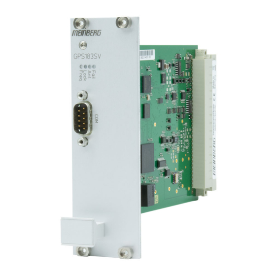
8 Installation 8.1 The Front Panel Layout Serial Interface COM0, 9-Pin DSUB Male Connector (Chapter 8.1.1) Status LEDs: Init/Nav./Ant/Fail (Chapter 8.1.2) Option: GPS Antenna, BNC, Female (Chapter 8.1.3) Date: May 21, 2024 GPS183SV... -
Page 29: Rs-232 Comx Time String Output
RS-232 Baud Rates: 19200 (Default), 9600, 4800, 2400, 1200, 600, 300 Framing: 7N2, 7E1, 7E2, 8N1 (Default), 8N2, 8E1, 8O1 COM x Time String Formats: Meinberg Standard (Default) Meinberg GPS NMEA RMC NMEA GGA NMEA ZDA NMEA RMC GGA (RMC followed by GGA) -
Page 30: Status Leds
The initialization of the internal firmware is complete but the oscillator is not yet locked to its phase reference. Green The initialization of the clock’s firmware is completed and the oscillator is locked to its phase reference. Date: May 21, 2024 GPS183SV... -
Page 31: Antenna Input: Gps Reference Clock
• Do not carry out any work on the antenna installation or the antenna cable if there is a risk of lightning strike. • Do not perform any work on the antenna installation if it is not possible to maintain the prescribed safety distance from exposed power lines or electrical substations. GPS183SV Date: May 21, 2024... -
Page 32: Installing A Gpsantv2
8.2.1 Selecting the Antenna Location There are essentially two ways a compatible Meinberg GPS Antenna (such as a GPSANTv2) can be installed using the accessories included: 1. Mounted on a pole 2. - Page 33 55 south parallels (satellite orbits). Information: Problems may arise with the synchronization of your Meinberg time server if these conditions are not met, as four satellites must be located to calculate the exact position. GPS183SV Date: May 21, 2024...
-
Page 34: Installation Of The Antenna
Fig. 3: Mounting a Meinberg GPS Antenna or GNSS Multi-Band Antenna onto a Pole Fig. 3 illustrates the mounting of a Meinberg Antenna on a pole by way of example. When mounting the antenna on a wall, the four wall plugs and M6x45 screws should be used to mount the two halves of the pole clamp (Fig. -
Page 35: Antenna Cable
Meinberg provides suitable cable types with its antennas and these are ordered together with the antenna to match the length you need from your antenna to your Meinberg reference clock. The route to be covered for your antenna installation should be determined and the appropriate cable type selected accordingly before confirming your order. - Page 36 • Any kinking, crushing, or other damage to the external insulation must be avoided. • Any damage or contamination of the coaxial connectors must be avoided. The bend radius is the radius at which a cable can be bent without sustaining damage (including kinks). Date: May 21, 2024 GPS183SV...
- Page 37 Compensating for Signal Propagation Time The propagation of the signal from the antenna to the receiver (reference clock) can incur a certain delay. This delay can be compensated for with Meinberg Device Manager Software. The signal propagation time can be compensated for by entering the length of the antenna cable under "Settings...
-
Page 38: Surge Protection And Grounding
Please refer to the standards regarding antenna installations (e.g., DIN EN 60728-11) for more information. However, in order to preserve the safety of the building and to protect your Meinberg system, Meinberg recomends the use of the MBG-S-PRO surge protector, which is addressed in more detail later in this chapter. - Page 39 Tighten the nut (Pos. 4) with a max. torque of 6 Nm. Once the antenna has been correctly installed with the grounding cable, connect the grounding cable to the bonding bar (see Fig. 5 and 6). GPS183SV Date: May 21, 2024...
- Page 40 The drawings below illustrate how a Meinberg GPS Antenna can be installed in accordance with the above conditions on a pole (e.g., antenna pole) or building roof. Antenna Installation without Insulated Lightning Rod System α Fig. 5: Installation on a Pole...
- Page 41 8 Installation Antenna Installation with Insulated Lightning Rod System α Fig. 6: Roof Installation Meinberg GPS Antenna Lightning Rod Lightning Rod Conductor Antenna Cable Bonding Conductor Bonding Bar Foundation Electrode Safety Zone GPS183SV Date: May 21, 2024...
- Page 42 Optional MBG S-PRO Surge Protector Information: The surge protector and suitable coaxial cable are not included as standard with a Meinberg GPS Antenna, but can be ordered as an optional accessory. Construction The MBG-S-PRO is a surge protector (Phoenix CN-UB-280DC-BB) for coaxial connections. It is patched directly into the antenna line and consists of a replaceable gas discharge tube that redirects the energy from the cable shielding to the ground potential when ignited.
- Page 43 Meinberg system in order to prevent destructive potential differences. Connect the coaxial cable from the antenna to one of the surge protector connectors, then connect the other surge protector connector to the coaxial cable leading to the Meinberg reference clock. Caution!
-
Page 44: Power Supply
8.3 Power Supply The power supply used with a GPS183SV has to provide only one output of +5V. The output voltage should be well regulated because drifting supply voltages reduce the short time accuracy of the generated frequencies and timing pulses. The power supply lines should have low resistance and must be connected using both pins a, b and c of the rear connector. -
Page 45: Using Meinberg Device Manager To Configure And Monitor The Gps183Sv
ZIP archive, and is also available for a variety of Linux distributions. To enable the GPS183SV to be correctly detected, configured, and monitored, Version 7.3 or better of Meinberg Device Manager is required. -
Page 46: Configuring The Gps183Sv
9.2 Configuring the GPS183SV This chapter describes the initial set-up process of a GPS183SV using Meinberg Device Manager. 9.2.1 “System” Section The "System" section can be used to perform basic operations such as the generation of a diagnostic file. To do this, select the device listed on the start page of Meinberg Device Manager. -
Page 47: Clock" Section
9 Using Meinberg Device Manager to Configure and Monitor the GPS183SV 9.2.2 “Clock” Section The following settings can be configured in the "Clock" section: Initialize Time: Allows the date and time to be modified manually. Use PC’s When enabled, the local PC’s... -
Page 48: Serial Ports" Section
This is used to select how frequently the time string as configured above should be output or whether it should only be output on request ("?" sent to the RxD pin of the serial interface). Date: May 21, 2024 GPS183SV... -
Page 49: Outputs" Section
9 Using Meinberg Device Manager to Configure and Monitor the GPS183SV 9.2.4 “Outputs” Section The IRIG time codes that can be output by the system can be configured here. This section can also be used to set the frequency and phase of the synthesizer and define the conditions under which the output signals are enabled. -
Page 50: Time Zone" Section
An offset must also be configured for summertime. DST Mode: It is also possible to specify a weekday on which the summertime starts and ends. Dynamic Calculation: Daylight Saving Time is applied or removed on the configured day of Date: May 21, 2024 GPS183SV... - Page 51 9 Using Meinberg Device Manager to Configure and Monitor the GPS183SV week, either on or after the configured date. (Example of CEST: First Sunday on or after March 25 and October 25). As such, the configuration only needs to be performed once and the appropriate date is calculated automatically each year.
-
Page 52: Monitoring The Gps183Sv
9.3 Monitoring the GPS183SV Once you have successfully logged into the GPS183SV, you can display the status of the device. The Dashboard shows all relevant system information: 9.3.1 “Overview” Section Device: The specific system name. Serial Number: The serial number of the device (please always specify when contacting Technical Support). - Page 53 9 Using Meinberg Device Manager to Configure and Monitor the GPS183SV Position Altitude: The altitude of the identified location. Position Altitude: The altitude of the identified location. Recent Event: The most recent event shown in an XML structure. GPS183SV Date: May 21, 2024...
-
Page 54: System" Section
9.3.2 “System” Section In addition to the information displayed under the "Overview" section, this section also shows the FPGA version, firmware version, serial number, and product designation. Date: May 21, 2024 GPS183SV... -
Page 55: Clock" Section
9 Using Meinberg Device Manager to Configure and Monitor the GPS183SV 9.3.3 “Clock” Section The Clock Status section provides important status information about your receiver module. For example, you can see the synchronization status of your receiver, the satellite constellations currently in use, and the number of satellites that are visible and/or in use. -
Page 56: Satellites" Section
Averaged C/NO The average quality of the satellites in the coordinate system (x = seconds, y = dBhz as unit for C/NO Carrier- to-Noise Density). Date: May 21, 2024 GPS183SV... -
Page 57: Event Log" Section
9 Using Meinberg Device Manager to Configure and Monitor the GPS183SV 9.3.5 “Event Log” Section This section is used to log system events and identify any changes. Clear Event Log - Deletes all displayed event logs. Save Event Log - Saves event logs as a text file. -
Page 58: Sensors" Section
9.3.6 “Sensors” Section This section allows the sensors integrated into the system to be monitored. Temperature 01: Displays the temperature measured at Sensor 01. Temperature 02: Displays the temperature measured at Sensor 02. Date: May 21, 2024 GPS183SV... -
Page 59: Configuration And Monitoring Using Gpsmon32
Windows 2000, Windows XP, and Windows NT. Meinberg ceased development of GPSMON32 in 2010 and ended official support in 2017. GPSMON32 was succeeded from that point by the newer Meinberg Device Manager, which provides many more features and is still in active development. -
Page 60: Technical Appendix
Baud Rate: 300 – 19200 Framing Options: 7N2, 7E1, 7E2, 8N1, 8N2, 8E1, 8O1 Default Setting: COM0: 19200, 8N1 Meinberg Standard string, transmission once per second COM1: 19200, 8N1 Meinberg Standard string, transmission once per second HF Connector: Coaxial BNC Connector, Female, for GPS Antenna... - Page 61 COM1 RxD in –USB COM0 RxD in *Not with TCXO oscillators / **Do Not Connect The assignments marked in blue are optional IMS Systems only Only receivers with XHS-SPI interface (IMS systems) Connector: 96-pin DIN 41612 connector GPS183SV Date: May 21, 2024...
-
Page 62: Technical Specifications: Oscillators
± 1 × 10⁸ ± 2 × 10¹⁰ Dependent Drift (–20 to 70 °C) (0 to 60 °C) (–10 to 70 °C) (–20 to 70 °C) (5 to 70 °C) (5 to 70 °C) in Free-Run Mode Date: May 21, 2024 GPS183SV... -
Page 63: Technical Specifications: Gpsantv2 Antenna
11 Technical Appendix 11.3 Technical Specifications: GPSANTv2 Antenna Physical Dimensions: GPS183SV Date: May 21, 2024... - Page 64 Connector Type: Type-N, Female Housing Material: ABS Plastic Case for Outdoor Installation IP Rating: IP65 Temperature Range: –60 C to +80 C (–76 F to 176 F) Weight: 1.4 kg (3.53 lbs), including mounting kit Date: May 21, 2024 GPS183SV...
-
Page 65: Technical Specifications: Mbg-S-Pro Surge Protector
Type-N, Female/Type-N, Female The original product page of the supplier (see link) of the CN-UB-280DC-BB surge protector provides detailed specifications, as well as a variety of product-specific documents under the link below: Data Sheet (Download): https://www.meinbergglobal.com/download/docs/shortinfo/german/cn-ub-280dc-bb_pc.pdf GPS183SV Date: May 21, 2024... -
Page 66: How Satellite Navigation Works
GPS receivers to be synchronized internally with the international UTC timescale. The receiver’s microprocessor can identify any time zone based on UTC time and automatically apply Day- light Saving Time adjustments over several years if so configured by the user. Date: May 21, 2024 GPS183SV... -
Page 67: Time String Formats
11.6 Time String Formats 11.6.1 Meinberg Standard Time String The Meinberg Standard Time String is a sequence of 32 ASCII characters starting with the <STX> (Start-of- Text) character and ending with the <ETX> (End-of-Text) character. The format is as follows: <STX>D:dd.mm.yy;T:w;U:hh.mm.ss;uvxy<ETX>... -
Page 68: Meinberg Gps Time String
<ETX> (End-of-Text) character. Unlike the Meinberg Standard Time String, the Meinberg GPS Time String does not carry any local time zone or UTC data; it simply carries the direct GPS time without any conversion into UTC. The format is as follows: <STX>D:dd.mm.yy;T:w;U:hh.mm.ss;uvGy;lll<ETX>... -
Page 69: Meinberg Capture String
11 Technical Appendix 11.6.3 Meinberg Capture String The Meinberg Capture String is a sequence of 31 ASCII characters terminated by a <CR><LF> (Carriage Return/Line Feed) sequence. The format is as follows: CHx<SP>dd.mm.yy_hh:mm:ss.fffffff<CR><LF> The letters printed in italics are replaced by ASCII-formatted numbers, whereas the other characters are directly part of the time string. -
Page 70: Atis Time String
(00–59, or 60 during leap second) Day of the Week (1–7, 1 = 31h = Monday) Checksum in hexadecimal, generated from all characters including GID, ABS, TSQ, CC, ST, etc. Carriage Return, ASCII code 0Dh <CR> Date: May 21, 2024 GPS183SV... -
Page 71: Sat Time String
Announcement of clock jump during last hour before jump enters effect: ‘!’ Announcement of start or end of Daylight Saving Time ‘ ‘ (Space, 20h) nothing announced Carriage Return, ASCII code 0Dh <CR> Line Feed, ASCII code 0Ah <LF> End-of-Text, ASCII code 03h <ETX> GPS183SV Date: May 21, 2024... -
Page 72: Uni Erlangen String (Ntp)
Leap second is currently to be inserted (only active in 60th second) ‘ ‘ (Space, 20h) No leap second to be inserted Geographical latitude of receiver position in degrees bbb.bbbb Leading characters padded by Space characters (20h) Date: May 21, 2024 GPS183SV... - Page 73 Longitudinal hemisphere, with the following characters possible: ‘E’ East of Greenwich Meridian ‘W’ West of Greenwich Meridian Altitude above WGS84 ellipsoid in meters hhhh Leading characters padded by Space characters (20h) End-of-Text, ASCII code 03h <ETX> GPS183SV Date: May 21, 2024...
-
Page 74: Nmea 0183 String (Rmc)
West of Greenwich Meridian Speed over the ground in knots and track angle in degrees. 0.0,0.0 With a Meinberg GPS clock, these values are always 0.0, With GNS clocks, the values are calculated by the receiver for mobile applications The date:... -
Page 75: Nmea 0183 String (Gga)
Geoid Separation (WGS84 Altitude - MSL Altitude) ggg.g Meters (unit as fixed value) Checksum (XOR of all characters except "$" and " * ") Carriage Return, ASCII code 0Dh <CR> Line Feed, ASCII code 0Ah <LF> GPS183SV Date: May 21, 2024... -
Page 76: Nmea 0183 String (Zda)
The date: dd,mm,yy Day of Month (01–31) Month (01–12) Year (0000–9999) yyyy Checksum (XOR of all characters except "$" and " * ") Carriage Return, ASCII code 0Dh <CR> Line Feed, ASCII code 0Ah <LF> Date: May 21, 2024 GPS183SV... -
Page 77: Abb Spa Time String
Checksum. This is calculated as the XOR sum of the preceding characters. The resultant 8-bit value is reported as a hex value in the form of two ASCII characters (0-9 or A-F) Carriage Return (ASCII code 0Dh) <CR> GPS183SV Date: May 21, 2024... -
Page 78: Computime Time String
Day of the week (1–7, 1 = Monday) The current time: hh:mm:ss Hours (00–23) Minutes (00–59) Seconds (00–59, or 60 during leap second) Carriage Return (ASCII code 0Dh) <CR> Line Feed (ASCII code 0Ah) <LF> Date: May 21, 2024 GPS183SV... -
Page 79: Racal Standard Time String
Control character, ASCII code 55h Current date: yymmdd Year of Century (00–99) Month (01–12) Day of Month (01–31) Current time: hh:mm:ss Hours (00–23) Minutes (00–59) Seconds (00–59, or 60 during leap second) Carriage Return, ASCII code 0Dh <CR> GPS183SV Date: May 21, 2024... -
Page 80: Sysplex-1 Time String
(00–59, or 60 during leap second) Quality Indicator Space (ASCII code 20h) Time Sync (GPS Lock) "?" (ASCII code 3Fh) No Time Sync (GPS Fail) Carriage Return (ASCII code 0Dh) <CR> Line Feed (ASCII code 0Ah) <LF> Date: May 21, 2024 GPS183SV... -
Page 81: Ion Time String
(00–59, or 60 while leap second) Quality Indicator Space (ASCII code 20h) Time Sync (GPS Lock) "?" (ASCII code 3Fh) No Time Sync (GPS Fail) Carriage Return (ASCII code 0Dh) <CR> Line Feed (ASCII code 0Ah) <LF> GPS183SV Date: May 21, 2024... -
Page 82: Ion Blanked Time String
(00–59, or 60 while leap second) Quality Indicator Space (ASCII code 20h) Time Sync (GPS Lock) "?" (ASCII code 3Fh) No Time Sync (GPS Fail) Carriage Return (ASCII code 0Dh) <CR> Line Feed (ASCII code 0Ah) <LF> Date: May 21, 2024 GPS183SV... -
Page 83: Irig-J Timecode
Day of the year (ordinal date, 1–366) Time of the start bit, specified in hours (HH), minutes (MM), seconds (SS) HH, MM, SS "Carriage Return" (ASCII code 0Dh) <CR> "Line Feed" (ASCII code 0Ah) <LF> GPS183SV Date: May 21, 2024... -
Page 84: 6021 Time String
UTC time, while the 3-bit value represented by the least significant bits 001 indicates that the day is Monday. Current time: hhmmss Hours (00–23) Minutes (00–59) Seconds (00–59, or 60 during leap second) Current date: ddmmyy (01–31) Month (01–12) Last two digits of year (00–99) Date: May 21, 2024 GPS183SV... - Page 85 For example, if the clock outputs A at these positions, this is equivalent to a binary sequence of 0x1010b. Please note that it is not the binary equivalent of the ASCII code itself. GPS183SV Date: May 21, 2024...
-
Page 86: Freelance Time String
UTC time, while the 3-bit value represented by the least significant bits 001 indicates that the day is Monday. Current time: hhmmss Hours (00–23) Minutes (00–59) Seconds (00–59, or 60 during leap second) Current date: ddmmyy (01–31) Month (01–12) Last two digits of year (00–99) Date: May 21, 2024 GPS183SV... - Page 87 For example, if the clock outputs A at these positions, this is equivalent to a binary sequence of 0x1010b. Please note that it is not the binary equivalent of the ASCII code itself. GPS183SV Date: May 21, 2024...
-
Page 88: Itu-G8271-Y.1366 Time-Of-Day Message
PPS. The ITU-G8271-Y.1366 time message itself output by Meinberg clocks is always a sequence of 21 bytes. While the standard briefly references the use of two ASCII characters for the first two characters, it should be noted that this message is not an ASCII string in the typical sense. -
Page 89: Cisco Ascii Time String
Sync state of clock: * : Clock is synchronized to reference !: Clock is not synchronized The format revision. With Meinberg clocks, this will always be ’A’. The current date in Modified Julian Date format. mjdxx The current date in Gregorian yy/mm/dd format. -
Page 90: Ntp Type 4 Time String
(00–59) Seconds (00–59, or 60 while leap second) Milliseconds (000–999) Leap second announcement: Space: No leap second announcement ’L’: Leap second pending Daylight Savings Time indicator: ’S’: Standard Time (wintertime) ’D’: Daylight Savings Time (summertime) Date: May 21, 2024 GPS183SV... -
Page 91: Programmable Pulse Signal Types
11 Technical Appendix 11.7 Programmable Pulse Signal Types Meinberg systems with programmable pulse outputs provide the following signal options; the actual range of available signal options will vary from system to system: Idle Selecting "Idle" disables that specific output. Timer In "Timer"... - Page 92 This mode is used to output a custom frequency, which is defined using the "Clock Synthesizer" section of the Web Interface. PTTI 1PPS This mode is used to pass a PPS signal of 20 s length through the output. Date: May 21, 2024 GPS183SV...
-
Page 93: Rohs Conformity
EU do not contain lead, cadmium, mer- cury, hexavalent chromium, polybrominated biphenyls (PBBs), polybrominated diphenyl ethers (PBDEs), bis(2-ethylhexyl)phthalat (DEHP), benzyl butyl ph- thalate (BBP), dibutyl phthalate (DBP), or diisobutyl phthalate (DIBP) above the legal limits. GPS183SV Date: May 21, 2024... -
Page 94: Declaration Of Conformity For Operation In The European Union
13 Declaration of Conformity for Operation in the European Union EU-Konformitätserklärung Doc ID: GPS183SV - Eurocard-May 21, 2024 Hersteller Meinberg Funkuhren GmbH & Co. KG Manufacturer Lange Wand 9, D-31812 Bad Pyrmont erklärt in alleiniger Verantwortung, dass das Produkt, declares under its sole responsibility, that the product... -
Page 95: Declaration Of Conformity For Operation In The United Kingdom
14 Declaration of Conformity for Operation in the United Kingdom 14 Declaration of Conformity for Operation in the United Kingdom UK Declaration of Conformity Doc ID: GPS183SV - Eurocard-May 21, 2024 Manufacturer Meinberg Funkuhren GmbH & Co. KG Lange Wand 9...
Need help?
Do you have a question about the GPS183SV and is the answer not in the manual?
Questions and answers