
Related Manuals for Everbrite Electronics ALL AMERICAN MP-5284R


Summary of Contents for Everbrite Electronics ALL AMERICAN MP-5284R
- Page 1 OPERATING INSTRUCTIONS AND SERVICE MANUAL BASKETBALL SCOREBOARD MODEL MP-5284R With MP-5000R Control EFFECTIVE S.N. 17,369 June 25, 2001...
-
Page 2: Table Of Contents
TABLE OF CONTENTS DESCRIPTION IDENTIFICATION DAMAGE DAMAGE CLAIM PROCEDURE INSTALLATION GENERAL INFORMATION INSPECTION PRE-TEST ELECTRICAL CONNECTIONS CONTROL CONSOLE OPERATION SCOREBOARD POWER CONSOLE DISPLAY CONSOLE POWER TO USE SCOREBOARD TIME OF DAY OPERATION TIME SETTING AND CONTROL FINAL MINUTE 1/10 SECOND TIME OPTION TEAM SCORES HORN 3.10... -
Page 3: Description
1. GENERAL INFORMATION 1.1 Description Your All-American scoreboard has been carefully inspected and tested before leaving the factory. It is possible, however, that components may be loosened or forced out of adjustment in transit. If this occurs, follow the troubleshooting guide (section 4). If equipment then fails to operate, contact immediately: ALL-AMERICAN Service Department EVERBRITE Corporation... -
Page 4: Inspection
If damage is discovered after delivery, you should call the delivery company. Have them make out a Concealed Damage Report. Fifteen days after delivery are allowed, so this should be done promptly or it is impossible to process this claim. Advise EVERBRITE corporation of necessary replacement parts, or repairs. -
Page 5: Electrical Connections
(D) Test operate all functions on the scoreboard according to operating instructions in section 3 of this manual. (E) When all the functions test out, disconnect the power and the control console before hanging the scoreboard. 2.4 Electrical connections This scoreboard requires a 120 V. 15 AMP AC circuit for the exclusive use of the scoreboard. -
Page 6: Console Power
3.3 Console Power Plug the hand held remote control into the scoreboard control console if you have a hand held time control. Plug the control console cable into the wall junction box. Push ON/OFF once to turn the console on. Push ON/OFF a second time to shut the console off. -
Page 7: Time Setting And Control
The scoreboard will now display Time of Day. If desirable, you may disconnect the control console and put it away. If at this time you want to use the scoreboard for a ball game, input the code and it will be set for the game. After the game, if you push DISPLAY TOD ENTER , you may... -
Page 8: Team Scores
3.8 Team Scores The Home and Guest Scores can be changed in five different ways. (A) To add 1 to the existing score: Push +1 . (B) To add 2 to the existing score: Push +2 . (C) To add 3 to the existing score: Push +3 . -
Page 9: Time Outs Left
Push: TIME OUT TIMER to start the 1 minute timer. The LCD will show "TIME OUT = 1:00" and start to count down. When 1 minute has elapsed the internal beeper sounds, and the display returns to the current game time. If you want to return to play before the Time Out Timer gets back to zero, push: TIME OUT... -
Page 10: Team Fouls
Time Out period ends, just push: TIME OUT CLEAR and the LCD will again go to the game display. 3.14 Ball Possession Indicator The ball possession indicators alternate with each BALL POSS entry. The possession is displayed on the LCD with a '<P' or 'P>' to show Home or Guest possession. -
Page 11: Wrestling Operation
push GAME DISPLAY . To clear a player number/foul from memory: push, PLAYER NO. followed by the number you want to clear, then CLEAR . ENTER 3.17 Wrestling Operation When using the MP-5214 scoreboard for wrestling, replace the basketball slipsheet with the wrestling slipsheet, The code is 60 for wrestling. -
Page 12: Maintenance And Troubleshooting
4. MAINTENANCE AND TROUBLESHOOTING 4.1 Introduction This section gives maintenance and troubleshooting information. Included are troubleshooting guides for typical scoreboard malfunctions. If the cause of a problem cannot be determined, please contact the customer service department. WARNING !!! 120 VAC wires are exposed whenever the cover over the power supply assembly is removed from the scoreboard. - Page 13 (C) The scoreboard digits light, the console works, but there is no control of the scoreboard. (a) With the main power switch "off"; remove the cover over the power supply, and receiver. (b) Check all connections. (c) Turn the main power on. (d) Turn the control console on and enter the code.
-
Page 14: Replacement Parts List
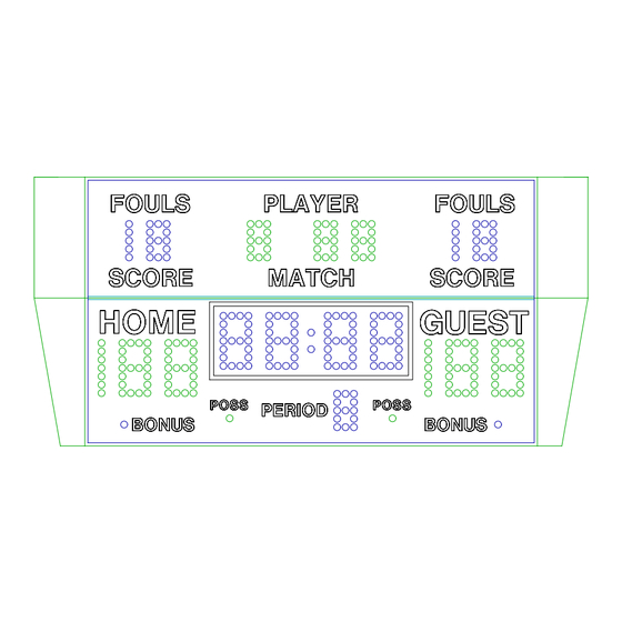
5. REPLACEMENT PARTS LIST 5.1 Scoreboard Display Parts figure 1 DISPLAY ASSEMBLY... - Page 15 REPLACEMENT PARTS LIST (MP-5284R Basketball) fig.& MFG PART VENDOR index NUMBER DESCRIPTION PART # 150783X Display Assembly 150783X 151036 Controller Assembly 151032 SEE FIGURE 2 151731 Power Supply Plate Assy 151731 SEE FIGURE 3 150822 Cluster, Green 150822 150820 Cluster, Red 150820 150821 Cluster, Amber...
-
Page 16: Controller Assembly Parts
5.2 Controller Assembly Parts figure 2 CONTROLLER ASSEMBLY REPLACEMENT PARTS LIST (MP-5284R) Controller Assy fig.& MFG PART VENDOR index NUMBER DESCRIPTION PART # 151036 Controller Assembly 151032 150635 PC Board Assy, 5000 Series Receiver 150635 ***** PROGRAM RX5.V102 ***** 150634 PC Board Assy, 4 Pos. -
Page 17: Power Supply Assembly Parts
5.3 Power Supply Assembly Parts figure 3 POWER SUPPLY PLATE ASSEMBLY REPLACEMENT PARTS LIST (MP-5284R) Power Suply Plate Assy fig.& MFG PART VENDOR index NUMBER DESCRIPTION PART # 151731 Power Supply Plate Assembly 151731 BL00054P Power Supply, 12V 150 Watt S-150-13-5 EL00525P Relay, 12 VDC... -
Page 18: Diagrams
6. DIAGRAMS 6.1 Control Console Keyboard and Slipsheet Layout for Basketball Operation for Wrestling Operation... - Page 19 6.1 Control Console Keyboard and Slipsheet Layout (cont.) for Volleyball Operation CONSOLE KEYBOARD...
-
Page 20: Scoreboard System Layout
6.2 Scoreboard System Layout SYSTEM LAYOUT... -
Page 21: Controller Assembly Wiring
6.3 Controller Assembly Wiring Diagram CONTROLLER WIRING... -
Page 22: Power Supply Diagram
6.4 Power Supply Diagram POWER SUPPLY... -
Page 23: Receiver Board Diagram
6.5 Receiver Board Diagram RECEIVER BOARD... -
Page 24: Driver Board Diagram
6.6 Driver Board Diagram DRIVER BOARD... -
Page 25: Microprocessor 4 X 7 Led Pattern (8 Bit)
6.7 Microprocessor 4 X 7 LED Pattern (8 Bit) MICROPROCESSOR 4 X 7 (8 BIT) LED PATTERN... -
Page 26: Installation Drawing
Installation Drawing INSTALLATION DRAWING...
Need help?
Do you have a question about the ALL AMERICAN MP-5284R and is the answer not in the manual?
Questions and answers