
Related Manuals for Everbrite Electronics All American Scoreboards MP-3814R


Summary of Contents for Everbrite Electronics All American Scoreboards MP-3814R
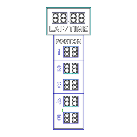
- Page 1 OPERATING INSTRUCTIONS AND SERVICE MANUAL RACETRACK SCOREBOARD MODEL MP-3814R EFFECTIVE S.N. 18,725, March 26, 2003...
-
Page 2: Table Of Contents
TABLE OF CONTENTS 1. GENERAL INFORMATION 1.1 DESCRIPTION 1.2 IDENTIFICATION 1.3 DAMAGE 1.4 DAMAGE CLAIM PROCEDURE 2. INSTALLATION 2.1 GENERAL INFORMATION 2.2 INSPECTION 2.3 ELECTRICAL CONNECTIONS 3. CONTROL CONSOLE OPERATION 3.1 CONSOLE DISPLAY 3.2 CONSOLE POWER 3.3 TIME TRIALS 3.4 RACE MODE 3.5 DIMMER 4. -
Page 3: General Information
1. GENERAL INFORMATION 1.1 DESCRIPTION Your All-American scoreboard has been carefully inspected and tested before leaving the factory. It is possible, however, that components may be loosened or forced out of adjustment in transit. If this occurs, follow the troubleshooting guide (section 4). If equipment then fails to operate, contact immediately: ALL-AMERICAN Service Department EVERBRITE Corporation... -
Page 4: Damage Claim Procedure
1.4 Damage Claim Procedure An instruction sheet is enclosed advising the consignee in case of damage in transit. If damage is noted at the time of delivery, consignee must obtain an 'Inspection of Bad Order' from the delivering carrier. In order to process your claim, this must be properly filled out with a complete statement of all damage and it must be signed by the carrier. -
Page 5: Inspection
2.2 Inspection Inspect each unit and tighten all screws, lamps, and fittings that may have loosened in shipment. 2.3 Installation Select the location best suited for visibility by the majority of spectators. Preferred position is facing east or north to avoid direct sunlight on the face of the scoreboard, if day races are held. -
Page 6: Time Trials
Push ON/OFF once to turn the console on. Push ON/OFF a second time to turn the console off. When first turned on; the LCD should show as follows: RACETRACK CONTROL VERSION 2.7 2001 Enter the code (88) as follows: Push CODE ENTER . -
Page 7: Race Mode
time trials. When the EE beam is broken the time will start. The 1/100th and 1/1000 digits are blanked while the timer is running. Push EE ENABLE at any time to disable the electric eye. When the EE beam is broken a second time, the time will stop and the hundredths and thousandths digits will display on the scoreboard and LCD display. -
Page 8: Dimmer
Push LAP or POS 1 through POS 10 then CLEAR to clear the respective locations. If a car drops out during the race, you may push POS 1 through POS 10 for the position that car was running in, then SHIFT , to clear that car number and shift all following positions up. -
Page 9: Troubleshooting Guide
4.4 Troubleshooting Guides (A) Scoreboard doesn't light (a) Check that the main power switch is turned on. (b) Replace any defective or blown fuses. (c) Check the power connections and voltages at the scoreboard. (d) Contact the Customer Service Department. (B) Scoreboard digits don't light, but the console works (a) With the main power switch "off";... - Page 10 (F) The scoreboard works, but some lights do not come on. IMPORTANT !!! In this scoreboard the 120 volt line is on the lamp socket all the time, and the common is switched to turn the lamps on and off. For this reason, to avoid damage to the equipment or personal injury, it is important to turn the main power off when changing the lamps.
-
Page 11: Replacement Parts List
5. REPLACEMENT PARTS LIST 5.1 Scoreboard Display Parts figure 1... - Page 12 DISPLAY ASSEMBLY REPLACEMENT PARTS LIST (MP-3814R Racetrack) fig.& MFG PART VENDOR index NUMBER DESCRIPTION PART # 151969 Display Set 151969 850030 Lamp, 25W/125V Clear 25A19 GR CL 151209 Controller Assembly 151209 *****SEE FIGURE 2***** SU00038 Fuse Box Assembly, SU00038 1-3A 121880 Fuse, 15A 250V F1-F7...
-
Page 13: Scoreboard Controller Assembly Parts
5.2 Scoreboard Controller Assembly Parts figure 2 CONTROLLER ASSEMBLY REPLACEMENT PARTS LIST (MP-3814R) Controller Assembly fig.& MFG PART VENDOR index NUMBER DESCRIPTION PART # 151209 Controller Assembly 151209 150040 Receiver PCB Assembly 150040 ***** PROGRAM 3PCNT19W ***** 118922 Driver PCB Assembly, 3 Position A4-A10 118922 EL00771P Transceiver, 2.4 GHZ 200MW... -
Page 14: Diagrams
6. DIAGRAMS 6.1 Control Console Keyboard and Slipsheet Layout CONSOLE KEYBOARD... -
Page 15: Scoreboard System Layout
6.2 Scoreboard System Layout SYSTEM LAYOUT... - Page 16 6.3 Junction Box Wiring...
- Page 17 SINGLE JUNCTION BOX WIRING 6.4 Power Wiring...
- Page 18 POWER WIRING 6.5 Controller Assembly Wiring...
-
Page 19: Microprocessor 4 X 7 Lamp Pattern (8 Bit)
CONTROLLER ASSEMBLY 6.6 Microprocessor 4 X 7 Lamp Pattern (8 Bit) MICROPROCESSOR 4 X 7 (8 BIT) LAMP PATTERN... - Page 20 6.7 Figuregram Wiring 8 BIT FIGUREGRAM WIRING...
-
Page 21: Jumper Location On 3 Position System
6.8 Jumper Location on 3 Position System All of the 3 position drivers and receivers are identical except for the jumper on each board. Make sure the jumpers are set for the model of scoreboard you are installing them into. (A) On the receiver board (refer to figure);... - Page 22 JUMPER LOCATION 6.9 Triac Placement The triac is the switch that controls the figuregram lamps. The triacs for any given figuregram are adjacent to the twelve pin connector on the driver board that controls that figuregram. Shown below is the triac placement and bit designation relative to the figuregram bit pattern.
-
Page 23: Installation Drawing (C-7816)
6.10 Installation Drawing... - Page 24 INSTALLATION DRAWING...
Need help?
Do you have a question about the All American Scoreboards MP-3814R and is the answer not in the manual?
Questions and answers