Table of Contents
Troubleshooting

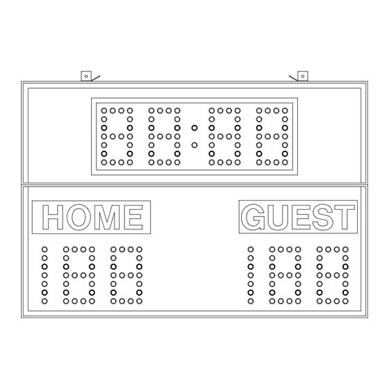
Related Manuals for Everbrite Electronics All American Scoreboards MP-2206


Summary of Contents for Everbrite Electronics All American Scoreboards MP-2206
- Page 1 A product of 401 S Main St Pardeeville, WI 53954 (608) 429-2121 / (800) 356-8146 OPERATING INSTRUCTIONS AND SERVICE MANUAL BASKETBALL SCOREBOARD MODEL MP-2206 WITH MP-3000 CONTROL EFFECTIVE S.N.XXXX, JAN 29,1998...
-
Page 2: Table Of Contents
TABLE OF CONTENTS GENERAL INFORMATION DESCRIPTION IDENTIFICATION DAMAGE DAMAGE CLAIM PROCEDURE INSTALLATION GENERAL INFORMATION INSPECTION PRE-TEST DATA CABLE INSTALLATION ELECTRICAL CONNECTIONS CONTROL CONSOLE OPERATION SCOREBOARD POWER CONSOLE DISPLAY CONSOLE POWER INITIALIZING SCOREBOARD TIME SETTING AND CONTROL FINAL MINUTE 1/10 SECOND TIME OPTION TEAM SCORES HORN TIMEOUT PERIOD... -
Page 3: General Information
1. GENERAL INFORMATION 1.1 DESCRIPTION Your All-American scoreboard has been carefully inspected and tested before leaving the factory. It is possible, however, that components may be loosened or forced out of adjustment in transit. If this occurs, follow the troubleshooting guide (section 4). If equipment then fails to operate, contact immediately: ALL-AMERICAN Service Department EVERBRITE Corporation... -
Page 4: Damage Claim Procedure
1.4 Damage Claim Procedure An instruction sheet is enclosed advising the consignee in case of damage in transit. If damage is noted at the time of delivery, consignee must obtain an 'Inspection of Bad Order' from the delivering carrier. In order to process your claim, this must be properly filled out with a complete statement of all damage and it must be signed by the carrier. -
Page 5: Inspection
2.2 Inspection Inspect each unit and tighten all screws, lamps, and fittings that may have loosened in shipment. NOTE A small length of rubber hose may be used as a lamp extractor. Simply taper the inside of the hose with a sharp knife to fit the lamp. 2.3 Pre-Test Before installing the scoreboard, pre-test all functions. -
Page 6: Control Console Operation
NOTE This equipment is ETL (Electronics Testing Laboratories) CSA and NRTL approved and complies with the requirements in part 15 of the FCC rules for a class A computing device. Operation of this equipment in a residential area may cause unacceptable interference to radio and television reception, requiring the operator to take whatever steps are necessary to correct the interference. -
Page 7: Time Setting And Control
When the proper code has been entered, the console display will show as follows. 3.5 Time Setting and Control To set an 8 minute period, Push: ENTER Any time up to 99:59 may be preset in a similar manner. UP/DN key determines the timer mode. -
Page 8: Horn
(D) To directly enter or correct a score: Push Home or Guest SCORE followed by the desired number, then ENTER . Example: Present Home Score is 15. Change the score from 15 to 23. Push: Home SCORE ENTER (E) To clear the score: Push SCORE CLEAR 3.8 Horn... -
Page 9: Test Equipment
removed from the scoreboard. Use extreme caution during troubleshooting or repair. To avoid possible damage to equipment or personal injury, always turn off the main power before removing the cover or replacing assemblies, or replacing lamps. 4.2 Test Equipment A simple analog or digital voltmeter will be sufficient for all user repairable problems. Printed circuit boards requiring troubleshooting should be returned to the factory. - Page 10 (c) If the continuity test checks good, check the voltage between the green wire and the white wire in the junction box, using a voltmeter set on the 12 VAC or higher scale. If the voltage is 0 VAC see the controller parts list for a transformer assembly.
-
Page 11: Replacement Parts List
equipment or personal injury, it is important to turn the main power off when changing lamps. (b) Check for a broken wire or bad connection on the 12 pin connector. (c) See the replacement parts list for the proper replacement driver board. 5. - Page 12 figure 1 DISPLAY ASSEMBLY REPLACEMENT PARTS LIST (MP-2206 Basketball) fig.& MFG PART VENDOR index NUMBER DESCRIPTION PART # 000000 Display Assembly 000000 850001 Lamp, 7C7/125V White 7C7/W 850002 Lamp, 7C7/125V Amber 7C7/A 850029 Lamp, 25W/130V Inside Frosted 25A19IF 180156 Controller Assembly 180156 *****SEE FIGURE 2***** 119337...
-
Page 13: Scoreboard Controller Assembly Parts
700618 Diode, 1N457A D1/D2 1N457A 5.2 Scoreboard Controller Assembly Parts figure 2 CONTROLLER ASSEMBLY REPLACEMENT PARTS LIST (MP-2206 Controller Assembly) fig.& MFG PART VENDOR index NUMBER DESCRIPTION PART # 180156 Controller Assembly 180156 150366 Receiver PCB Assembly 150366 *** PROGRAM 3MP-CNT-V00*** 150368 Driver PCB Assembly, 5 Position A4-A5... -
Page 14: Diagrams
151300 Horn Suppressor Assy. 151300 700520 Varistor, ERZ-C20DK201U 700850 Capacitor, 0.02 MFD 400V. CD-1000203M0Z5U 705075 Ribbon Cable Assy, W/2 Fem.Connectors AS-1053 2-10 HB005600 Cover HB005600 2-11 705723 Spacer, P.C.Board LCBS-6-01 6. DIAGRAMS 6.1 Control Console Keyboard and Slipsheet Layout... -
Page 15: Scoreboard System Layout
CONSOLE KEYBOARD 6.2 Scoreboard System Layout... - Page 16 SYSTEM LAYOUT 6.3 Single Wall Junction Box Wiring...
- Page 17 SINGLE JUNCTION BOX WIRING 6.4 Dual Wall Junction Box Wiring...
- Page 18 DUAL JUNCTION BOX WIRING...
- Page 19 6.5 Controller Assembly Wiring...
-
Page 20: Line Filter Wiring Diagram (B-151507)
CONTROLLER ASSEMBLY 6.6 Line Filter Wiring Diagram... -
Page 21: Microprocessor 4 X 7 Lamp Pattern (8 Bit)
LINE FILTER WIRING 6.7 Microprocessor 4 X 7 Lamp Pattern (8 Bit) MICROPROCESSOR 4 X 7 (8 BIT) LAMP PATTERN 6.8 Figuregram Wiring... - Page 22 8 BIT FIGUREGRAM WIRING Jumper Location on 5 Position System...
-
Page 23: Triac Placement Diagram
JUMPER LOCATION 6.10 Triac Placement The triac is the switch that controls the figuregram lamps. The triacs for any given figuregram are adjacent to the twelve pin connector on the driver board that controls that figuregram. Shown below is the triac placement and bit designation relative to the figuregram bit pattern. MP TRIAC PLACEMENT 6.11 Installation Drawing... -
Page 24: Installation Drawing
INSTALLATION DRAWING...
Need help?
Do you have a question about the All American Scoreboards MP-2206 and is the answer not in the manual?
Questions and answers