Table of Contents
Advertisement
Quick Links
Advertisement
Table of Contents

Related Manuals for THORLABS MCLS1-CUSTOM


Summary of Contents for THORLABS MCLS1-CUSTOM
- Page 1 MCLS1-CUSTOM Multi-Channel Fiber-Coupled Laser Source User Guide...
-
Page 2: Table Of Contents
4-Channel Fiber-Coupled Laser Source Table of Contents Chapter 1 Introduction ....................... 1 1.4.1 Specifications ..............................2 1.4.2 Mechanical Drawings ............................4 1.5.1 List of Available Light Sources ..........................5 1.5.2 Front and Back Panel Overview ........................... 6 Chapter 2 Safety ......................... 9 Chapter 3 Installation ....................... - Page 3 4-Channel Fiber-Coupled Laser Source Chapter 8 Disposal ........................18 Chapter 9 Thorlabs Worldwide Contacts ................... 19...
-
Page 5: Chapter 1 Introduction
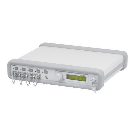
Description The Thorlabs 4-Channel Fiber Coupled Laser Sources provide easy coupling and simple control of laser diode driven fiber optics. Each system is equipped with up to four fiber output light sources with wavelength available from visible to IR. -
Page 6: Specifications
There is a 3 second delay before the lasers turns on, and the user is warned by the LED rapidly blinking. The MCLS1-CUSTOM includes a universal power supply allowing operation over 100 - 240 VAC without the need for selecting the line voltage. The fuse access is conveniently located on the rear panel. This unit is supplied with a region-specific U.S. - Page 7 4-Channel Fiber-Coupled Laser Source Chapter 1: Introduction Performance Specifications Display Power Accuracy ±10% Current Set Point Resolution 0.01 mA Temperature Adjust Range 20.00 to 30.00 °C Temp Set Point Resolution ±0.01 °C Noise <0.5% Typical (Source Dependent) Rise Time / Fall Time <5 µs Modulation Input 0 - 5 V = 0 - Full Power...
-
Page 8: Mechanical Drawings
4-Channel Fiber-Coupled Laser Source Chapter 1: Introduction 1.4.2 Mechanical Drawings Figure 1 Mechanical Drawing Page 4 TTN182036-D02... -
Page 9: List Of Available Light Sources
4-Channel Fiber-Coupled Laser Source Chapter 1: Introduction Components 1.5.1 List of Available Light Sources The table below lists the standard available system light sources. Laser Source Typical λ Range Typical Monitor Name λ (nm) (nm) Power Power Laser Type Fiber MCLS1-406 395 - 415 4.0 mW... -
Page 10: Front And Back Panel Overview
4-Channel Fiber-Coupled Laser Source Chapter 1: Introduction Laser Source Typical λ Range Typical Monitor Name λ (nm) (nm) Power Power Laser Type Fiber MCLS1-1310 1310 1290-1330 2.5 mW 3.0 mW Fabry-Perot SMF-28e+ MCLS1-1310-15 1310 1290-1330 13.0 mW 15.0 mW Fabry-Perot SMF-28e+ MCLS1-1310DFB 1310... - Page 11 4-Channel Fiber-Coupled Laser Source Chapter 1: Introduction Cooling Vent – Do Not Block The temperature control system moves air from vent holes on the bottom. Periodically remove AC Power Cord Connector dust buildup from vents for best operation. Remote Interlock Input Modulation Input - 0 to 5 V Max Accepts complex waveforms.
- Page 12 4-Channel Fiber-Coupled Laser Source Chapter 1: Introduction Simplified Declaration of Conformity FCC Designation This equipment has been tested and found to comply with the limits for a Class A digital device, pursuant to part 15 of the FCC Rules. These limits are designed to provide reasonable protection against harmful interference when Page 8 TTN182036-D02...
-
Page 13: Chapter 2 Safety
4-Channel Fiber-Coupled Laser Source Chapter 2: Safety the equipment is operated in a commercial environment. This equipment generates, uses, and can radiate radio frequency energy and, if not installed and used in accordance with the instruction manual, may cause harmful interference to radio communications. - Page 14 4-Channel Fiber-Coupled Laser Source Chapter 2: Safety Laser Safety This device can only be returned when packed into the complete original packaging, including all packing inserts. If necessary, ask for a replacement package. Per 21 C.F.R. §1040.10 and IEC 60825-1:2014+A11:2021, the MCLS2-CUSTOM series of lasers are rated in the 3B Laser Safety Class.
-
Page 15: Chapter 3 Installation
If necessary, ask for replacement packaging. Refer servicing to qualified personnel. Packing List • MCLS1-CUSTOM Multi Channel Fiber Coupled Light Source • Operating Manual • 120 VAC US Power Supply Line Cord, when purchased in the US or 230 VAC Power Supply Line Cord for Europe •... -
Page 16: Chapter 4 Operation
Setting the AC Line Voltage and Installing Fuses Your MCLS Series Laser Source has been shipped from Thorlabs configured for 100 to 240 VAC operation. There is no line switch adjustment to be made. However, it may be necessary to replace an open fuse. To do this you must perform the following procedure. - Page 17 4-Channel Fiber-Coupled Laser Source Chapter 4: Operation Viewing Channel Information The MCLS uses a single LCD display to access the information for each output channel. At any time, the display can be adjusted to view another channel by simply rotating the control knob located to the left of the display. The display will scroll through the channels until the desired channel is selected.
- Page 18 4-Channel Fiber-Coupled Laser Source Chapter 4: Operation temperature set point. The temperature default is 25.00 C but can be adjusted over a range of 20.00 to 30.00 C with a resolution of 0.01 C. Note: As above, there is a timeout where the display will revert to the viewing display and lock out adjustment to the temperature.
-
Page 19: Chapter 5 Making The Safety Interlock Connections
SYSTEM ENABLE switch. All units shipped from Thorlabs are configured with a shorting device installed in the Interlock connector. If you are not going to use this feature, then you can leave the shorting device installed and the unit will operate normally as described in the procedures above. -
Page 20: Chapter 6 Remote Communications
Card that was included with your unit, or by visiting to download and install the latest www.thorlabs.com/manuals software for the MCLS Series Fiber-Coupled Laser Source. From the dialog box that is displayed, select the Install Drivers button. Follow the onscreen prompts to install the driver. After the driver is installed, attach the MCLS Fiber-Coupled Laser Source to the PC and power it on. - Page 21 4-Channel Fiber-Coupled Laser Source Chapter 6: Remote Communications Keywords (Commands and Queries) The following list shows all the available commands and queries, and summarizes their functions: Command Syntax Description Get Commands Lists the available commands. Get ID Returns the model number and firmware version. Get Channel channel? Returns the active channel.
-
Page 22: Chapter 7 Maintenance And Cleaning
Allowing dust and dirt into the fiber ports will degrade coupling efficiency and possibly damage the fiber patch cords, both inside and outside. If you suspect this to be true, Thorlabs can clean and inspect the fiber connections, and repair if necessary. - Page 23 4-Channel Fiber-Coupled Laser Source Chapter 9: Thorlabs Worldwide Contacts Chapter 9 Thorlabs Worldwide Contacts For technical support or sales inquiries, please visit us at for our most up-to-date www.thorlabs.com/contact contact information. Corporate Headquarters Product Manufacturer Thorlabs, Inc. Thorlabs, Inc. 43 Sparta Ave...
- Page 24 www.thorlabs.com...
Need help?
Do you have a question about the MCLS1-CUSTOM and is the answer not in the manual?
Questions and answers