Advertisement
Quick Links
Safety Precautions
WARNING! Read and fully understand the user manual before operating this product.
Please use this equipment carefully and observe all warnings and cautions.
protective clothing and eyewear when dispensing chemicals or other materials or when working in the
WEAR
vicinity of all chemicals, filling or emptying equipment, or changing metering tips.
observe safety and handling instructions of the chemical manufacturer.
ALWAYS
direct discharge away from you or other persons or into approved containers.
dispense cleaners and chemicals in accordance with manufacturer's instructions. Exercise CAUTION when
maintaining your equipment.
reassemble equipment according to instruction procedures. Be sure all components are firmly screwed or
latched into position.
equipment clean to maintain proper operation.
KEEP
only to water tap outlets (25 psi Minimum, 85 psi Maximum and Maximum water temperature 120° F).
ATTACH
If the unit is used to fill a sink, or the discharge hose can be placed into a sink. The unit must be mounted
NOTE
so that the bottom of the cabinet is above the overflow rim of the sink.
Device shall be installed in a vertical orientation.
A plumbed, dedicated line is preferred for installation. When a dedicated line is not available, installation shall
ensure that no cross-connections between hot and cold water are created, and that atmospheric vacuum
breakers integrated into the building water supply are not negatively affected by being under pressure for
over 12 continuous hours.
introduction
Package Contents
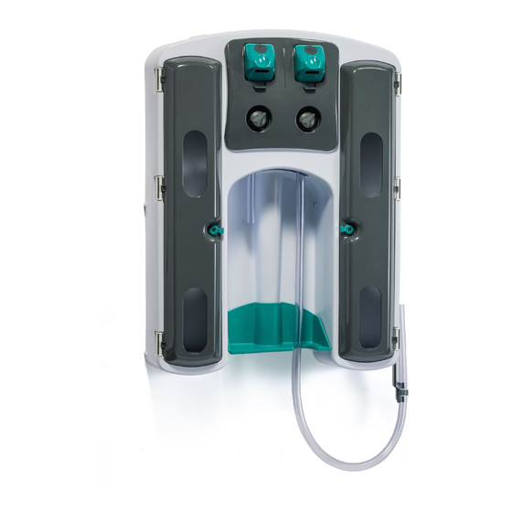
1) Proportioning unit
2) Supply tubing
3) Wall bracket, mounting hardware
4) Foot strainers, weights, in-line check valves, hose barb "Y"
installation and operation
Installation
1. Find suitable place close to a water source for unit. Remove wall bracket from packaging, place level on wall and mark (3)
mounting holes. Drill (3) 5/16" holes and install anchors in wall. Secure wall bracket to wall with screws and washers provided.
NOTE: The distance from the top of the wall bracket to the top of the cabinet is 1/8".
2. Place the cabinet onto the wall bracket aligning the tabs with the slots in the top of the cabinet. Also ensure the central snap
on top of the wall bracket engages the cabinet. Mark the wall using the (2) lower holes, as guides, then remove cabinet from
wall. Drill (2) 5/16" holes and install anchors in wall.
3. Select metering tips (up to four) for each selector valve (See next two sections.) Push each tip firmly into a separate hose
barb extending from the selector valve. A tip with no hole (clear plastic) can be used to block any valve port not being used
for chemical. (This may be used for dispensing water only.)
4. Cut supply tube provided into separate supply tubes for each product dispensed. Use "Y" fittings to connect both high and
low flow eductor to a single container. Supply tubes should reach from hos barb on eductor select valve to the bottom of
container for easy replacement of chemical. (See diagram page 3.) Prepare a tube for each barb of the select valve.
Supply tube routing to lower containers should pass through the circular notch in the shelf back. NOTE: ARROW ON IN-LINE
CHECK VALVES SHOULD BE POINTED TOWARD THE EDUCTOR.
AccuMax 4P
™
THANK YOU FOR YOUR INTEREST IN OUR PRODUCTS
user manual
with HydroGap AirGap Eductors
5) Metering tip kits (2)
6) Discharge tubing for each eductor
7) Hose hook for 3.5 GPM eductor
™
For Model 3578AG
1
Advertisement

Summary of Contents for Hydro AccuMax 4P
- Page 1 AccuMax 4P with HydroGap AirGap Eductors ™ ™ For Model 3578AG Safety Precautions WARNING! Read and fully understand the user manual before operating this product. THANK YOU FOR YOUR INTEREST IN OUR PRODUCTS Please use this equipment carefully and observe all warnings and cautions.
- Page 2 installation and operation (continued) 5. If required, the optional Foam/Froth Reducing Tube can slide on the end of the grey 1 GPM eductor. Push the tube as far as possible. Warm the end of the tube for easy installation. This tube will reduce the amount of foam that may occur with some chemicals.
- Page 3 parts diagram Access for Maintenance Single Pick-up Dual Pick-up Part No. Description Part No. Description HYD10098395 Door, right side HYD160 1.0 GPM eductor - Gray HYD10098394 Door, left side HYD161 3.5 GPM eductor - Yellow HYD10098821 Button, Bottle fill, process blue HYD10080920 Selector replacement kit HYD10098824...
- Page 4 Hydro Systems Phone 513.271.88OO...


Need help?
Do you have a question about the AccuMax 4P and is the answer not in the manual?
Questions and answers