Table of Contents
Advertisement
Quick Links
Advertisement
Table of Contents

Related Manuals for EPH Controls RFC V2


Summary of Contents for EPH Controls RFC V2
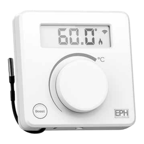
- Page 1 RF Cylinder Thermostat with Boost Button Installation and Operation Guide...
-
Page 2: Table Of Contents
Table of contents Installation Instructions Factory Default Settings Speci cations How a RFC Room Thermostat works Mounting & Installation Mounting of Temperature Sensor Operating Instructions LCD Symbol Description Button Description Replacing the Batteries Battery Low Warning Boost Function Locking the Keypad... - Page 3 Adjusting the Target Temperature To connect a RFC to a R_7-RF To connect a RFC to a UFH10-RF To disconnect a RFC from both R_7-RF or UFH10-RF Menu Function P0 1 Setting High & Low Limits P0 2 Hysteresis P0 3 Calibration P0 4 Resetting the Thermostat...
-
Page 4: Installation Instructions
Cylinder Thermostat Installation Instructions... -
Page 5: Factory Default Settings
External sensor length: 1950mm ± 80mm Temperature indication: ˚C Switching di erential: Adjustable 0.0 … 10˚C Note: Good quality batteries are essential to ensure the correct operation of this product. EPH recommend using Duracell or Energiser batteries. EPH Controls Ltd. -
Page 6: How A Rfc V2 Room Thermostat Works
How a RFC Cylinder Thermostat works When a RFC thermostat is calling for heat, it will operate according to the target temperature selected by the user. The target temperature is de ned by turning the dial clockwise for a higher target temperature or anti-clockwise for a lower target temperature. -
Page 7: Mounting & Installation
Prior to setting the thermostat, it is necessary to complete all required ƒ settings described in this section. This thermostat can be mounted in the following ways: 1) To a recessed conduit box 2) To a surface mounted box 3) Directly mounted on a wall EPH Controls Ltd. - Page 8 Mounting & Installation Continued 1) Remove the thermostat from its packaging. 2) Choose a mounting location so that the thermostat can measure the temperature as accurately as possible. - Choose a mounting location for the temperature probe as per the instructions on Page 8. - Prevent direct exposure to sunlight or other heating / cooling sources.
- Page 9 φ 5 Temperature Sensor Wall mounted...
-
Page 10: Mounting Of Temperature Sensor
Mounting of Temperature Sensor 1. Cylinder Surface The temperature sensor should be tted on the bottom 1/3 of the cylinder. Remove a section of insulation on the cylinder to reveal the copper surface. Attach the temperature sensor to the surface of the cylinder using the foil tape provided. - Page 11 Mount the NTC sensor housing 1.5 meters above oor level. Ensure the temperature sensor is secured tightly in the NTC sensor housing. Note: NTC sensor housing can be purchased as an accessory from EPH Controls. Product code: NTC-Housing EPH Controls Ltd.
-
Page 12: Operating Instructions
Cylinder Thermostat Operating Instructions... -
Page 13: Lcd Symbol Description
LCD Symbol Description Cylinder temperature Battery low symbol Wireless symbol Installer Menu Keypad lock symbol Limit Heating ON symbol EPH Controls Ltd. -
Page 14: Button Description
Button Description Set point handwheel Boost button Boost Boost External probe Release button RF button KEY3 Reset button... -
Page 15: Replacing The Batteries
Insert the 2 x AAA batteries and the thermostat will turn on. Reattach front housing to baseplate. Battery Low Warning When the batteries are almost empty, the symbol will appear on the screen. The batteries must now be replaced or the unit will shut down. EPH Controls Ltd. -
Page 16: Boost Function
Boost Function The thermostat can be boosted for 30 minutes, 1, 2 or 3 hours. Press 1, 2, 3 or 4 times, to apply the desired boost period. Boost To cancel a boost, press again. Boost Locking the Keypad To lock the thermostat, press and hold for 10 seconds. - Page 17 5. On the R_7-RF Put the next thermostat into pairing mode or press to return to the main screen. Note: When pairing additional zones to a R_7-RF ‘r02’ , ‘r03’, ‘r04’ can appear on the thermostat screen. EPH Controls Ltd.
- Page 18 To connect a RFC to a UFH10-RF 1. On the UFH10-RF: , ‘P01 rF COn’ will appear on the screen. Press MENU , ‘RF CONNECT’ will appear solid on the screen. Press Rotate to choose the zone you would like to connect to. Press to con rm.
- Page 19 Press the twice to con rm. The thermostat is now disconnected from the. Note: The thermostats can also be disconnected at the R_7-RF or UFH10-RF. Please see R_7-RF or UFH10-RF operation guide for details. EPH Controls Ltd.
- Page 20 Menu Function This menu allows the user to adjust additional functions. P0 1: Setting High and Low limits P0 2: Hysteresis HOn & HOFF P0 3: Calibration P0 4: Resetting the Thermostat P0 1 Setting High & Low limits Hi 90°C Lo 10°C This menu allows the installer to change the minimum and maximum temperatures that the thermostat can operate between.
- Page 21 The settings will be saved and the user will be returned to the previous screen. Press to return to normal operation. When limits are set Boost on the thermostat the word ‘LIM’ will be displayed on the screen permanently. EPH Controls Ltd.
- Page 22 P0 2 Hysteresis HOn 5°C HOFF 0.0°C This menu allows the installer to change the hysteresis of the thermostat when the temperature is rising and falling. If HOn is set to 5˚C, this will allow a temperature drop of 5˚C below the target temperature, before the thermostat turns on again.
- Page 23 Press to con rm the temperature. The current temperature will be saved and the user will be returned to the previous screen. Press to return to normal operation. Boost EPH Controls Ltd.
- Page 24 P0 4 – Resetting the Thermostat This menu allows the user to reset the thermostat to factory settings. To access this setting, press and hold together Boost for 5 seconds. ‘P01’ will appear on the screen Rotate until ‘P04 & rSt’ appears on the screen. Press to con rm.
- Page 25 Notes...
- Page 26 Notes...
- Page 27 Notes...
- Page 28 EPH Controls IE technical@ephcontrols.com www.ephcontrols.com/contact-us +353 21 471 8440 Cork, T12 W665 EPH Controls UK technical@ephcontrols.co.uk www.ephcontrols.co.uk/contact-us +44 1933 322 072 Harrow, HA1 1BD...
Need help?
Do you have a question about the RFC V2 and is the answer not in the manual?
Questions and answers