Subscribe to Our Youtube Channel
Summary of Contents for Stavoklima Nevada JET
- Page 1 A I R H E A T I N G U N I T S T A V O K L I M A Installation and operation manual Nevada JET model www.stavoklima.cz version C...
-
Page 2: Table Of Contents
Setting up and disassembly of the outlet nozzle ......................6 Air flow reach graph ..............................7 Unit installation ................................8 ZS-Nevada JET suspensions under ceiling ....................... 8 Connection of the unit to heating system ........................10 Heat exchanger control with a valve with electrothermic head ................11 Setting of independent valve flow pressure (ETVQ) ..................... -
Page 3: Unpacking, Check After Transport Or Warehousing
Nevada JET heating unit Unpacking, check after transport or warehousing Unpacking and check Carefully check the delivery note attached to the delivery. For components identified as extra accessories in the delivery note (not included in the unit or installed therein), please check completeness to the parcel and perfect condition (usually delivered in a separate box). -
Page 4: Storing Of The Unit, Additional Transport Recommendations
Installation and operation manual Storing of the unit, additional transport recommendations Observe packaging decals on the unit. The device in its packaging must not be turned or placed in transport positions other than those supplied and recommended by the manufacturer. -
Page 5: Dimensions Of The Unit
Nevada JET heating unit Full performance of the unit may be provided only when maintenance is regular and proper. All controls are accessible and well maintained. Technical conditions for unit operation: max. media working temperature 90°C/pressure 1.6MPa – unless specified otherwise, ... -
Page 6: Setting Up And Disassembly Of The Outlet Nozzle
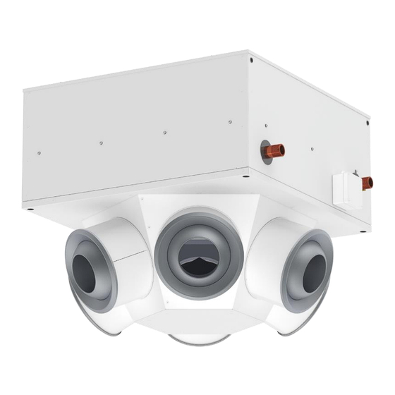
Installation and operation manual Setting up and disassembly of the outlet nozzle The long-range nozzles are used in particular where the supplied air must span large distances between the nozzle and the zone of stay. This is in case where large spaces (halls etc.) does not permit or make unsuitable to arrange for uniform air supply through ceiling anemostats. -
Page 7: Air Flow Reach Graph
Air flow reach graph Exemplary graph reading: 1) Mounting height H Nevada JET unit is 6,8 m. 2) Using the values in table on page 6, an optimum angle was selected, which is 45° in this exemplary case (grey curve). -
Page 8: Unit Installation
(M10 threads) are installed on the unit from production plant. Upon special purchase order, the following is supplied as accessories to the ZS-Nevada JET under-ceiling suspensions: 4 pcs M10x1000 - 8.8 thread bar, 4 pcs M10/40 anchor, 4 pcs M10 suspension lug, 8 pcs M10 - 8.8 nuts, 4 pcs M10x45 - 8.8 bolt, 4 pcs big flat washer size 10, 4 pcs spring washers size 10. - Page 9 Nevada JET heating unit Keep minimum distance from the ceiling and wall in order to fully use the output of the unit. Regardless orientation of the assembly, always make sure that entry to the air curtain unit is spaced at least one fan diameter from the wall or ceiling.
-
Page 10: Connection Of The Unit To Heating System
Installation and operation manual Connection of the unit to heating system Please check all hot water connections for readiness and perfect condition before connecting media to the unit. Furthermore, please check the hot distribution for components or other measures to ensure zero transmission of static, dynamic, and dilatation forces at the input and output neck connections. -
Page 11: Heat Exchanger Control With A Valve With Electrothermic Head
Nevada JET heating unit Heat exchanger control with a valve with electrothermic head The electrothermic valve drive can be supplied to the hot water heat exchanger as not embedded either as 2- way (ETVQ) or 3-way (ETVT). “Normally open” version (NO). -
Page 12: Electric Connection Of The Unit
Installation and operation manual Electric connection of the unit The heating unit must be protected by a suitable circuit breaker according to its electric parameters – refer to attached electric wiring. The connection terminals on the hot water unit are accessible after unscrewing the cover of the fan wiring box. The connection terminals on the unit with electric heater are accessible after unscrewing the cover. -
Page 13: Commissioning, Starting Of The Unit
Nevada JET heating unit Type of control Unireg DIT EC Unireg DIT EC 400 Unireg BMS EC Unireg BMS EC 400 Type of unit Nevada N3 JET Nevada N4 JET Nevada N3 JET Nevada N4 JET Unit power supply 230V... -
Page 14: Optional Accessories - Depending On Equipment Level
The Nevada JET heating units are supplied without a filter in front of the heat exchanger in standard, and therefore, special attention needs to be paid to the heat exchanger condition check. The regularity of checks depend on environment in which the device is operated. -
Page 15: Troubleshooting
Nevada JET heating unit Troubleshooting Problem Possible cause Remedy Unit circuit-breaker is off Turn on Mains failure Inspection Anti-freeze protection* (refer to Unireg The unit can not be turned on Inspection DIT) Controller position “0”* Check, > position than “0”... - Page 16 Installation and operation manual STAVOKLIMA s.r.o. Budějovická 450, 370 01 Homole Tel.: +420 387 001 931 e-mail: info@stavoklima.cz www.stavoklima.cz Technical changes reserved...


Need help?
Do you have a question about the Nevada JET and is the answer not in the manual?
Questions and answers