Table of Contents
Advertisement
Quick Links
Advertisement
Table of Contents

Related Manuals for VIA Technologies SOM-3000


Summary of Contents for VIA Technologies SOM-3000
- Page 1 QUICK START GUIDE VIA SOM-3000 Evaluation Kit 1.01-24052024...
- Page 2 VIA Technologies, Inc. reserves the right to make changes to the products described in this manual at any time without prior notice.
- Page 3 VIA SOM-3000 Evaluation Kit Quick Guide Safety Precautions • Always read the safety instructions carefully. • Keep this document for future reference. • All cautions and warnings on the equipment should be noted. • Keep this equipment away from humidity.
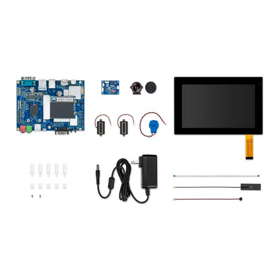
- Page 4 VIA SOM-3000 module with 2.0GHz MediaTek Genio 350 Quad-Core SoC @ Quad-Core SoC, 16GB eMMC, 2GB LPDDR4 SDRAM, Wi-Fi 5, 2.0GHz Bluetooth 5.0 VIA SOM-3000 Evaluation kit with VIA SOM-3000 module, VIA STK-SOM935-00A0 VAB-935 carrier board and accessory kit Optional Accessories Wireless Module Options...
-
Page 5: Table Of Contents
Connecting the Speakers........................2 Connecting the Microphone ......................... 3 Connecting the RTC Battery ........................3 Securing the VIA SOM-3000 Carrier Board ................... 4 Connecting the LCD Touch Panel ......................6 Connecting the FFC Cable to Debug Board and Host PC ............... 7... - Page 6 Figure 08: Connecting the 30-pin FFC cable of the Touch panel to 'J9' ..............6 Figure 09: Connecting the 4-pin FFC cable to 'UART0' on the VIA SOM-3000 module ........7 Figure 10: Connecting the 4-pin FFC cable to the 4-pin FFC port on the debug board ........7...
-
Page 7: Overview
VIA SOM-3000 Evaluation Kit Quick Guide 1. Overview This guide describes how to assemble the VIA SOM-3000 Evaluation Kit to test the VIA SOM-3000 module's functionality with the VIA VAB-935 carrier board. Notes: The operating temperature 0 C ~ 60 C is a result of testing performed in a testing chamber, and a number of variables can influence this result. -
Page 8: Connecting The Wi-Fi Antenna
VIA SOM-3000 Evaluation Kit Quick Guide 2.2 Connecting the Wi-Fi Antenna Connect the provided dual band Wi-Fi antenna to the I-PEX connector labeled 'J1' lon the VIA SOM-3000 module as shown below. Figure 02: Connecting the Wi-Fi antenna Note: Using a mating/unmating jig is recommended for connecting the antenna to the I-PEX connector on the VIA SOM- 3000 module. -
Page 9: Connecting The Microphone
VIA SOM-3000 Evaluation Kit Quick Guide 2.4 Connecting the Microphone Connect the provided microphone to the MIC connector labeled 'J20' on the VIA VAB-935 carrier board as shown below. Figure 04: Connecting the microphone 2.5 Connecting the RTC Battery Connect the provided RTC battery to the RTC battery connector labeled 'BAT1' on the VIA VAB-935 carrier board as shown below. -
Page 10: Securing The Via Som-3000 Carrier Board
VIA SOM-3000 Evaluation Kit Quick Guide 2.6 Securing the VIA SOM-3000 Carrier Board Keeping the carrier board's top side facing up, insert the M3*20mm bolts into the 5 mounting holes from above and insert the M3*10mm bolts into the 5 mounting holes from below. -
Page 11: Figure 06: Securing The Via Vab-935 Carrier Board
VIA SOM-3000 Evaluation Kit Quick Guide Figure 06: Securing the VIA VAB-935 Carrier Board... -
Page 12: Connecting The Lcd Touch Panel
VIA SOM-3000 Evaluation Kit Quick Guide 2.7 Connecting the LCD Touch Panel Caution: To prevent the LCD Touch Panel's metal shell from shorting PCBA pins below, it is highly recommended to apply insulation mylar or a piece of paper pasting on the LCD Touch Panel's metal shell before connecting the LCD Touch Panel's plug connector to the carrier board. -
Page 13: Connecting The Ffc Cable To Debug Board And Host Pc
Follow the steps below to connect the provided 4-pin FFC cable to the provided USB-to-UART debug board and a host PC: Step 1 Insert one plug connector of the 4-pin FFC cable into the J3 port labeled 'UART0' on the VIA SOM-3000 module, ensuring that the gold finger of the FFC cable faces down. UART0 Port... -
Page 14: Connecting The Power Adapter
VIA SOM-3000 Evaluation Kit Quick Guide Step 3 Connect a Windows 10 host machine through the Micro USB 2.0 port on the USB-to-UART debug board using a Micro USB cable. 2.9 Connecting the Power Adapter Connect the provided 12V AC power adapter to the DC-in jack on the VIA VAB-935 carrier board as shown below. - Page 15 Taiwan Headquarters Japan China 1F, 531 Zhong-zheng Road, 940 Mission Court 3-15-7 Ebisu MT Bldg. 6F, Tsinghua Science Park Bldg. 7 Xindian Dist., New Taipei City 231 Fremont, CA 94539, Higashi, Shibuya-ku No. 1 Zongguancun East Road, Taiwan Tokyo 150-0011 Haidian Dist., Beijing, 100084 Japan China...
Need help?
Do you have a question about the SOM-3000 and is the answer not in the manual?
Questions and answers