
Related Manuals for ASROCK P4S61


Summary of Contents for ASROCK P4S61
- Page 1 P4S61 User Manual Version 1.0 Published October 2003 Copyright©2003 ASRock INC. All rights reserved.
- Page 2 (including damages for loss of profits, loss of business, loss of data, interruption of business and the like), even if ASRock has been advised of the possibility of such damages arising from any defect or error in the manual or product.
-
Page 3: Table Of Contents
3.1.1 BIOS Menu Bar ............. 16 3.1.2 Legend Bar ............16 3.2 Main Menu ............... 17 3.3 Advanced, Security, Power, Boot, and Exit Menus ..19 4 Software Support ........... 20 4.1 Installing Operating System ..........20 4.2 Support CD Information ........... 20 4.2.1 Running Support CD .......... -
Page 4: Introduction
ASRock’s commitment to quality and endurance. Chapter 1 and 2 of this manual contain introduction of the motherboard and step-by- step installation guide for new DIY system builders. Chapter 3 and 4 contain basic BIOS setup and Support CD information. -
Page 5: Specifications
1.2 Specifications Platform: Micro ATX Form Factor: 9.6-in x 8.4-in, 24.4 cm x 21.3 cm ® ® ® CPU: Socket 478 for Intel Pentium 4 / Celeron processor Chipsets: North Bridge: SiS 661FX chipset, FSB @ 800/533/400MHz, supports Hyper-Threading Technology South Bridge: SiS 963L chipset, supports USB 2.0, ATA 133... - Page 6 CPU and the heatsink when you install the PC system. Do NOT use a 3.3V AGP card on the AGP slot of P4S61 motherboard! It may cause permanent damage! Power Management for USB 2.0 works fine under Microsoft ®...
-
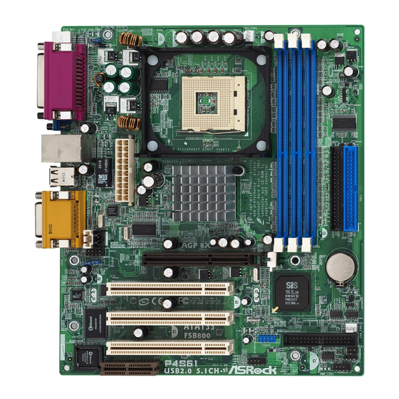
Page 7: Motherboard Layout
USB 2.0 Header (USB45, Blue) CPU Fan Connector (CPU_FAN1) Serial Port Connector (COM1) North Bridge Controller AMR Slot (AMR1) 184-pin DDR DIMM Slots (DDR DIMM1- 3) Flash Memory Secondary IDE Connector (IDE2, Black) AUDIO CODEC Primary IDE Connector (IDE1, Blue) -
Page 8: Asrock I/O
1.4 ASRock I/O Parallel Port Line Out (Lime) RJ-45 Port USB 2.0 Ports Game Port VGA Port Microphone (Pink) PS/2 Keyboard Port (Purple) Line In (Light Blue) PS/2 Mouse Port (Green) -
Page 9: Installation
y. -
Page 10: Cpu Installation
CPU into the socket to avoid bending of the pins. Step 4. When the CPU is in place, press it firmly on the socket while you push down the socket lever to secure the CPU. The lever clicks on the side tab to indicate that it is locked. -
Page 11: Installation Of Memory Modules (Dimm)
DIMMs or the system components. Step 1. Unlock a DIMM slot by pressing the retaining clips outward. Step 2. Align a DIMM on the slot such that the notch on the DIMM matches the break on the slot. notch break... -
Page 12: Expansion Slots
AMR slot: The AMR slot is used to insert an ASRock MR card (optional) with v.92 Modem functionality. AGP slot: The AGP slot is AGP 3.5 compliant and it supports an 8X / 4X AGP card. Do NOT use a 3.3V AGP card on the AGP slot of P4S61 motherboard! -
Page 13: Jumpers Setup
Note: To select +5VSB, it requires 2 Amp and higher standby current provided by power supply. (see p.7 item 25) (see p.7 item 24) Note: If the jumpers JL1 and JR1 are short, both front panel and rear panel audio connectors can work. Clear CMOS Solder Points (CLRCMOS1) solder points (see p.7 item 11) -
Page 14: Connectors
FLOPPY1 Pin1 (see p.7 item 15) the red-striped side to Pin1 Note: Make sure the red-striped side of the cable is plugged into Pin1 side of the connector. Primary IDE connector (Blue) Secondary IDE connector (Black) (39-pin IDE1, see p.7 item 9) (39-pin IDE2, see p.7 item 8) - Page 15 (CD1: see p.7 item 28) AUX1 a CD-ROM, DVD/ROM, TV (AUX1: see p.7 item 27) tuner card, or MPEG card. Front panel audio connector This is an interface for front +5VA BACKOUT-R panel audio cable that allows (9-pin AUDIO1) BACKOUT-L convenient connection and (see p.7 item 26)
-
Page 16: Bios Setup
Flash Memory on the motherboard stores the BIOS Setup Utility. When you start up the computer, there is a chance for you to run the BIOS Setup. Press <F2> during the Power-On-Self-Test (POST) to enter the BIOS Setup Utility, otherwise, POST continues with its test routines. -
Page 17: Main Menu
Enter:Select Sub-Menu System Date [Month/Day/Year] Set the system date that you specify. Valid values for month, day, and year are Month: (Jan to Dec), Day: (1 to 31), Year: (up to 2099). Use keys to move between the Month, Day and Year fields. - Page 18 If the auto- detection fails, it may due to that the hard disk is too old or too new. If the hard disk was already formatted on an older system, the BIOS Setup may detect incorrect parameters.
-
Page 19: Advanced, Security, Power, Boot, And Exit Menus
LBA Mode This allows user to select the LBA mode for a hard disk > 512 MB under DOS and Windows; for Netware and UNIX user, select [Off] to disable the LBA mode. -
Page 20: Software Support
This motherboard supports various Microsoft Windows operating systems: 98 SE / ME / 2000 / XP. Because motherboard settings and hardware options vary, use the setup procedures in this chapter for general reference only. Refer to your OS documentation for more information. -
Page 21: Appendix
Microsoft Windows ® ® XP. Set to [Auto] if using Microsoft Windows XP, or Linux kernel version 2.4.18 or higher. This option will be hidden if the current CPU does not support Hyper-Threading technology. - Page 22 CPU host frequency among the following sets of values: [72 MHz / 36 MHz], [64 MHz / 32 MHz], [77 MHz / 39 MHz], [67 MHz / 34 MHz], and the default value is [Sync].
- Page 23 OnBoard Serial Port: Use this to set addresses for the onboard serial ports or disable serial ports. Configuration options: [Auto], [Disabled], [3F8 / IRQ4 / COM1], [2F8 / IRQ3 / COM2], [3E8 / IRQ4 / COM3], [2E8 / IRQ3 / COM4]. OnBoard Infrared Port: You may select [Enabled] or [Disabled] for this...
- Page 24 Configuration options: [Auto], [Disabled], [378], [278]. Parallel Port Mode: Set the operation mode of the parallel port. The default value is [ECP+EPP]. If this option is set to [ECP+EPP], it will show the EPP version in the following item, “EPP Version”.
-
Page 25: Security Menu
Set User Password: Press <Enter> to set User Password. Valid password can be a 1 to 6 alphanumeric characters combination. If you already have a password, you must enter your current password first in order to create a new p assword. -
Page 26: Power Menu
Ring-In Power On: Use this to enable or disable Ring-in signals to turn on the system from the power-soft-off mode. PCI Devices Power On: Use this to enable or disable PCI devices to turn on the system from the power-soft-off mode. -
Page 27: Boot Menu
F10:Save & Exit :Select Menu Enter:Select Sub-Menu Quick Boot Mode: Enable this mode will speed up the boot-up routine by skipping memory retestings. Boot Up Num-Lock: If this is enabled, it will automatically activate the Numeric Lock function after boot-up. -
Page 28: Exit Menu
BIOS SETUP Utility without making any changes to the settings. Load Default Settings: After you enter the submenu, the message “Load default settings” will appear. If you press <Enter>, it will load the default values for all the setup configuration.
Need help?
Do you have a question about the P4S61 and is the answer not in the manual?
Questions and answers