
Related Manuals for ASROCK P43ME - V1.1

Summary of Contents for ASROCK P43ME - V1.1
-
Page 1: User Manual
P43ME User Manual Version 1.1 Published May 2009 Copyright©2009 ASRock INC. All rights reserved. 1 1 1 1 1... - Page 2 (including damages for loss of profits, loss of business, loss of data, interruption of business and the like), even if ASRock has been advised of the possibility of such damages arising from any defect or error in the manual or product.
-
Page 3: Table Of Contents
2.10 SATAII Hard Disk Setup Guide ........26 2.11 Serial ATA (SATA) / Serial ATAII (SATAII) Hard Disks Installation ..............27 2.12 Hot Plug Function for SATA / SATAII HDDs ....27 2.13 SATA / SATAII HDD Hot Plug Feature and Operation Guide ................28 2.14 Driver Installation Guide .......... - Page 4 3.4.6 Floppy Configuration ........... 50 3.4.7 Super IO Configuration ........50 3.4.8 USB Configuration ..........52 3.5 Hardware Health Event Monitoring Screen ....53 3.6 Boot Screen ..............54 3.6.1 Boot Settings Configuration ........54 3.7 Security Screen ............55 3.8 Exit Screen ..............
-
Page 5: Introduction
ASRock’s commitment to quality and endurance. In this manual, chapter 1 and 2 contain introduction of the motherboard and step-by-step guide to the hardware installation. Chapter 3 and 4 contain the configuration guide to BIOS setup and information of the Support CD. -
Page 6: Specifications
Specifications Specifications Specifications 1 . 2 1 . 2 Specifications Specifications - Micro ATX Form Factor: 9.6-in x 8.3-in, 24.4 cm x 21.1 cm Platform - LGA 775 for Intel Core 2 Extreme / Core 2 Quad / Core ®... - Page 7 - 24 pin ATX power connector - 4 pin 12V power connector - CD in header - Front panel audio connector - 2 x USB 2.0 headers (support 4 USB 2.0 ports) (see CAUTION 9) - 8Mb AMI BIOS BIOS Feature - AMI Legal BIOS - Supports “Plug and Play”...
- Page 8 Overclocking may affect your system stability, or even cause damage to the components and devices of your system. It should be done at your own risk and expense. We are not responsible for possible damage caused by overclocking.
- Page 9 . With ® this utility, you can press <F6> key during the POST or press <F2> key to BIOS setup menu to access ASRock Instant Flash. Just launch this tool and save the new BIOS file to your USB flash drive, floppy disk or hard drive, then you can update your BIOS only in a few clicks without prepar- ing an additional floppy diskette or other complicated flash utility.
-
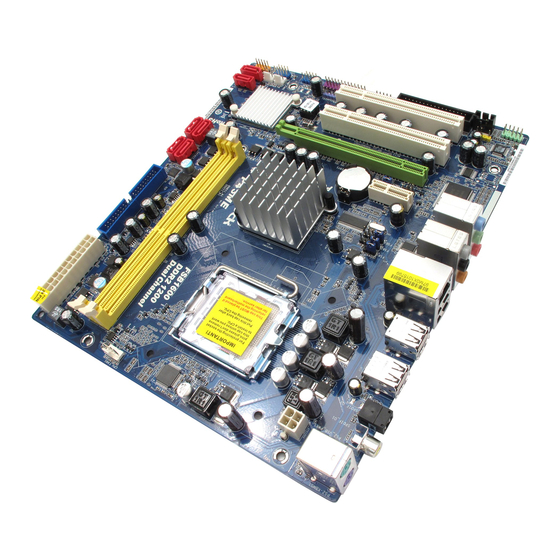
Page 10: Motherboard Layout
(HDMI_SPDIF1, Yellow) South Bridge Controller PCI Slots (PCI1 - 2) Fifth SATAII Connector (SATAII_5, Red) PCI Express 2.0 x16 Slot (PCIE2, Green) Sixth SATAII Connector (SATAII_6, Red) Infrared Module Header (IR1) System Panel Header (PANEL1, Orange) PCI Express x1 Slot (PCIE1) -
Page 11: I/O Panel
Coaxial SPDIF Out Port ** 7 Front Speaker (Lime) PS/2 Keyboard Port (Purple) * There are two LED next to the LAN port. Please refer to the table below for the LAN port LED indications. LAN Port LED Indications ACT/LINK... - Page 12 To enable Multi-Streaming function, you need to connect a front panel audio cable to the front panel audio header. After restarting your computer, you will find “VIA HD Audio Deck” tool on your system. Please follow below instructions according to the OS you install.
-
Page 13: Installation
Chapter 2: Installation Chapter 2: Installation This is a Micro ATX form factor (9.6" x 8.3", 24.4 x 21.1 cm) motherboard. Before you install the motherboard, study the configuration of your chassis to ensure that the motherboard fits into it. -
Page 14: Cpu Installation
Before you insert the 775-LAND CPU into the socket, please check if the CPU surface is unclean or if there is any bent pin on the socket. Do not force to insert the CPU into the socket if above situation is found. - Page 15 PnP cap to assist in removal. 1. It is recommended to use the cap tab to handle and avoid kicking off the PnP cap. 2. This cap must be placed if returning the motherboard for after service.
-
Page 16: Installation Of Heatsink And Cpu Fan
CPU and the heatsink to improve heat dissipation. Ensure that the CPU and the heatsink are securely fastened and in good contact with each other. Then connect the CPU fan to the CPU_FAN connector (CPU_FAN1, see page 10, No. -
Page 17: Installation Of Memory Modules (Dimm)
DIMMs or the system components. Step 1. Unlock a DIMM slot by pressing the retaining clips outward. Step 2. Align a DIMM on the slot such that the notch on the DIMM matches the break on the slot. notch break... -
Page 18: Expansion Slots (Pci And Pci Express Slots)
2.6 Expansion Slots (PCI and PCI Express Slots) 2.6 Expansion Slots (PCI and PCI Express Slots) There are 2 PCI slots and 2 PCI Express slots on this motherboard. PCI Slots: PCI slots are used to install expansion cards that have the 32-bit PCI interface. PCIE Slots: PCIE1 (PCIE x1 slot) is used for PCI Express cards with x1 lane width cards, such as Gigabit LAN card, SATA2 card, etc. -
Page 19: Jumpers Setup
After waiting for 15 seconds, use a jumper cap to short pin2 and pin3 on CLRCMOS1 for 5 seconds. However, please do not clear the CMOS right after you update the BIOS. - Page 20 Please use jumper to force NB to be strapped at higherfrequency, so the DRAM can work at lower frequency. If you want to overclock the CPU you adopt to FSB1066 on this motherboard, you need to adjust the jumpers. Please short pin2, pin3 for FSB1 jumper, pin4, pin5 for FSB2 jumper, and pin4, pin5 for FSB3 jumper.
-
Page 21: Onboard Headers And Connectors
(see p.10 No. 24) FLOPPY1 Pin1 the red-striped side to Pin1 Note: Make sure the red-striped side of the cable is plugged into Pin1 side of the connector. Primary IDE connector (Blue) (39-pin IDE1, see p.10 No. 7) IDE1 PIN1... - Page 22 USB 2.0 Headers Besides six default USB 2.0 USB_PWR ports on the I/O panel, there are (9-pin USB8_9) DUMMY two USB 2.0 headers on this (see p.10 No. 19) motherboard. Each USB 2.0...
-
Page 23: Chassis/Power Fan Connectors
Though this motherboard provides 4-Pin CPU fan (Quiet Fan) support, the 3-Pin CPU fan still can work successfully even without the fan speed control function. If you plan to connect the 3-Pin CPU fan to the CPU fan connector on this motherboard, please connect it to Pin 1-3. - Page 24 (see p.10 No. 6) Though this motherboard provides 24-pin ATX power connector, it can still work if you adopt a traditional 20-pin ATX power supply. To use the 20-pin ATX power supply, please plug your power supply along with Pin 1 and Pin 13.
-
Page 25: Hdmi_Spdif Header Connection Guide
HDMI (High-Definition Multi-media Interface) is an all-digital audio/video specification, which provides an interface between any compatible digital audio/ video source, such as a set-top box, DVD player, A/V receiver and a compatible digital audio or video monitor, such as a digital television (DTV). A complete HDMI system requires a HDMI VGA card and a HDMI ready motherboard with a HDMI_SPDIF header. -
Page 26: Sataii Hard Disk Setup Guide
Before installing SATAII hard disk to your computer, please carefully read below SATAII hard disk setup guide. Some default setting of SATAII hard disks may not be at SATAII mode, which operate with the best performance. In order to enable SATAII function, please follow the below instruction with different vendors to correctly adjust your SATAII hard disk to SATAII mode in advance;... -
Page 27: Installation
STEP 3: Connect one end of the SATA data cable to the motherboard’s SATAII connector. STEP 4: Connect the other end of the SATA data cable to the SATA / SATAII hard disk. It is not recommended to switch the “Configure SATAII as” setting after OS installation. -
Page 28: Guide
SATA / SATAII driver is available on our support website: www.asrock.com 4. Make sure to use the SATA power cable & data cable, which are from our motherboard package. 5. Please follow below instructions step by step to reduce the risk of HDD crash... - Page 29 Please do follow below instruction sequence to process the Hot Unplug, improper procedure will cause the SATA / SATAII HDD damage and data loss. Step 1 Unplug SATA data cable from SATA / SATAII HDD side. Unplug SATA 15-pin power cable connector (Black) from SATA / SATAII HDD side. Step 2...
-
Page 30: Driver Installation Guide
2 . 1 4 Driver Installation Guide To install the drivers to your system, please insert the support CD to your optical drive first. Then, the drivers compatible to your system can be auto-detected and listed on the support CD driver page. Please follow the order from up to bottom side to install those required drivers. -
Page 31: Tm Tm
AHCI driver. After reading the floppy disk, the driver will be presented. Select ® the driver to install according to the mode you choose and the OS you install. You may select: "Intel(R) ICH10 SATA AHCI Controller (Desktop - Windows XP)" for Windows ®... -
Page 32: Untied Overclocking Technology
BIOS setup to set the selection from [Auto] to [CPU, PCIE, Async.]. Therefore, CPU FSB is untied during overclocking, but PCI / PCIE buses are in the fixed mode so that FSB can operate under a more stable overclocking environment. -
Page 33: Bios Setup Utility
Power-On-Self-Test (POST) to enter the BIOS SETUP UTILITY, otherwise, POST will continue with its test routines. If you wish to enter the BIOS SETUP UTILITY after POST, restart the system by pressing <Ctl> + <Alt> + <Delete>, or by pressing the reset button on the system chassis. -
Page 34: Navigation Keys
Main Screen 3 . 2 3 . 2 Main Screen 3 . 2 Main Screen Main Screen When you enter the BIOS SETUP UTILITY, the Main screen will appear and display the system overview. BIOS SETUP UTILITY Smart Advanced H/W Monitor... -
Page 35: Smart Screen
. Just launch ® this tool and save the new BIOS file to your USB flash drive, floppy disk or hard drive, then you can update your BIOS only in a few clicks without preparing an additional floppy diskette or other complicated flash utility. -
Page 36: Advanced Screen
BIOS files and their respective information. Select the proper BIOS file to update your BIOS, and reboot your system after BIOS update process completes. 3 . 4 3 . 4 Advanced Screen 3 . 4 Advanced Screen Advanced Screen Advanced Screen 3 . - Page 37 Ratio CMOS Setting If the ratio status is unlocked, you will find this item appear to allow you changing the ratio value of this motherboard. If the CPU you adopt supports EIST (Intel (R) SpeedStep(tm) tech.), and you plan to adjust the ratio value, please disable the option “...
- Page 38 Intel (R) C-STATE tech. is achieved by making the power and thermal control unit part of the core logic and not part of the chipset as before. Migration of the power and thermal management flow into the processor allows us to use a hardware coordination mechanism in which each core can request any C-state it wishes, thus allowing for individual core savings to be maximized.
-
Page 39: Chipset Configuration
[333MHz (DDR2 667)], [400MHz (DDR2 800)], [533MHz (DDR2 1066)] or [600MHz (DDR2 1200)]. The configuration options depend on the CPU and memory module you adopt on this motherboard. Please refer to page 8 for the CPU FSB frequency and its corresponding memory support frequency. - Page 40 DRAM tRCD This controls the number of DRAM clocks for TRCD. Min: 3. Max: 10. The default value is [Auto]. DRAM tRP This controls the number of DRAM clocks for TRP. Min: 3. Max: 10. The default value is [Auto].
- Page 41 DRAM CH0 G0 (Data) This controls the number of DRAM CH0 G0 (Data). Min: 1. Max: 15. The default value is [Auto]. DRAM CH0 G1 (Command) This controls the number of DRAM CH0 G1 (Command). Min: 1. Max: 15. The default value is [Auto].
- Page 42 DRAM tRD Settings DRAM CH0 tRD This controls the number of DRAM CH0 tRD. Min: 0. Max: 30. The default value is [Auto]. DRAM CH1 tRD This controls the number of DRAM CH1 tRD. Min: 0. Max: 30. The default value is [Auto].
- Page 43 DRAM CH0 CTRL1 SKEW This controls the number of DRAM CH0 CTRL1 SKEW. Configuration options: [Auto], [-350 ps], [-300 ps], [-250 ps], [-200 ps], [-150 ps], [-100 ps], [-50 ps] and [Normal]. The default value is [Auto]. DRAM CH0 CTRL2 SKEW This controls the number of DRAM CH0 CTRL2 SKEW.
- Page 44 [Auto]. GLTRef Voltage Use this to select GLTRef Voltage. Configuration options: [Auto], [0.67 x Vtt], [0.65 x Vtt], [0.63 x Vtt] and [0.615 x Vtt]. The default value of this feature is [Auto]. NB Voltage Use this to select NB Voltage. Configuration options: [Auto], [1.11V], [1.21V], [1.30V] and [1.40V].
- Page 45 Select [Auto], [Enabled] or [Disabled] for the onboard HD Audio Front Panel. OnBoard Lan This allows you to enable or disable the “OnBoard Lan” feature. CIR10 Field 1 Use this to enable or disable CIR10 Field 1. The default value of this feature is [Enabled].
-
Page 46: Acpi Configuration
Use this item to enable or disable Ring-In signals to turn on the system from the power-soft-off mode. PCI Devices Power On Use this item to enable or disable PCI devices to turn on the system from the power-soft-off mode. PS/2 Keyboard Power On Use this item to enable or disable PS/2 keyboard to turn on the system from the power-soft-off mode. -
Page 47: Ide Configuration
Then in the option “Configure SATAII as”, you are allowed to set the selec- tion to [IDE] or [AHCI]. The default value is [IDE]. If you select [AHCI] mode, the option “Hot Plug” will appear. You are allowed to use the Hot Plug function under Windows environment if this option is enabled. - Page 48 [ARMD]: This is used for IDE ARMD (ATAPI Removable Media Device), such as MO. LBA/Large Mode Use this item to select the LBA/Large mode for a hard disk > 512 MB under DOS and Windows; for Netware and UNIX user, select [Disabled] to disable the LBA/Large mode.
-
Page 49: Pcipnp Configuration
Use this item to enable or disable the S.M.A.R.T. (Self-Monitoring, Analysis, and Reporting Technology) feature. Configuration options: [Disabled], [Auto], [Enabled]. 32-Bit Data Transfer Use this item to enable 32-bit access to maximize the IDE hard disk data transfer rate. 3.4.5 3.4.5 3.4.5 PCIPnP Configuration... -
Page 50: Floppy Configuration
Use this item to enable or disable floppy drive controller. Serial Port Address Use this item to set the address for the onboard serial port or disable it. Configuration options: [Disabled], [3F8 / IRQ4], [2F8 / IRQ3], [3E8 / IRQ4], [2E8 / IRQ3]. - Page 51 Parallel Port Mode Use this item to set the operation mode of the parallel port. The default value is [ECP+EPP]. If this option is set to [ECP+EPP], it will show the EPP version in the following item, “EPP Version”. Configuration options: [Normal], [Bi-Directional], and [ECP+EPP].
-
Page 52: Usb Configuration
[Enabled] - Enables support for legacy USB. [Auto] - Enables legacy support if USB devices are connected. [Disabled] - USB devices are not allowed to use under legacy OS and BIOS setup when [Disabled] is selected. If you have USB compatibility issue, it is recommended to select [Disabled] to enter OS. -
Page 53: Hardware Health Event Monitoring Screen
3 . 5 Hardware Health Event Monitoring Screen In this section, it allows you to monitor the status of the hardware on your system, including the parameters of the CPU temperature, motherboard temperature, CPU fan speed, chassis fan speed, and the critical voltage. -
Page 54: Boot Screen
Boot Screen Boot Screen 3 . 6 3 . 6 Boot Screen In this section, it will display the available devices on your system for you to config- ure the boot settings and the boot priority. BIOS SETUP UTILITY Main Smart... -
Page 55: Security Screen
Security Screen Security Screen 3 . 7 3 . 7 Security Screen In this section, you may set or change the supervisor/user password for the system. For the user password, you may also clear it. BIOS SETUP UTILITY Main Smart... -
Page 56: Exit Screen
BIOS SETUP UTILITY. Discard Changes and Exit When you select this option, it will pop-out the following message, “Dis- card changes and exit setup?” Select [OK] to exit the BIOS SETUP UTILITY without saving any changes. Discard Changes When you select this option, it will pop-out the following message, “Dis-... -
Page 57: Install Operating System
4 . 2 . 4 4 . 2 . 4 C o n t a c t I n f o r m a t i o n C o n t a c t I n f o r m a t i o n...
Need help?
Do you have a question about the P43ME - V1.1 and is the answer not in the manual?
Questions and answers