
Related Manuals for Tektronix Keithley 2290-5


Summary of Contents for Tektronix Keithley 2290-5
- Page 1 www.keithley.com Model 2290-5 5 kV Power Supply User’s Manual 2290-5-900-01 Rev. A / December 2013 *P2290590001A* 2290-5-900-01 A Greater M esure of Confidence A T ektr onix Company...
- Page 2 Model 2290-5 5 kV Power Supply User's Manual © 2013, Keithley Instruments, Inc. Cleveland, Ohio, U.S.A. All rights reserved. Any unauthorized reproduction, photocopy, or use of the information herein, in whole or in part, without the prior written approval of Keithley Instruments, Inc. is strictly prohibited. All Keithley Instruments product names are trademarks or registered trademarks of Keithley Instruments, Inc.
- Page 3 Safety precautions The following safety precautions should be observed before using this product and any associated instrumentation. Although some instruments and accessories would normally be used with nonhazardous voltages, there are situations where hazardous conditions may be present. This product is intended for use by qualified personnel who recognize shock hazards and are familiar with the safety precautions required to avoid possible injury.
- Page 4 For safety, instruments and accessories must be used in accordance with the operating instructions. If the instruments or accessories are used in a manner not specified in the operating instructions, the protection provided by the equipment may be impaired. Do not exceed the maximum signal levels of the instruments and accessories, as defined in the specifications and operating information, and as shown on the instrument or test fixture panels, or switching card.
-
Page 5: Table Of Contents
Table of Contents Introduction ....................... 1-1 Welcome ..........................1-1 Extended warranty ....................... 1-1 Contact information ......................1-1 CD-ROM contents ........................ 1-2 Organization of manual ......................1-2 Features ..........................1-3 Unpacking and inspecting ....................1-3 Inspect for damage ........................1-3 Shipment contents ........................1-3 Optional accessories ...................... - Page 6 Table of Contents Model 2290-5 5 kV Power Supply User's Manual Set current trip ........................3-7 Remote operation ..................... 4-1 Introduction .......................... 4-1 Connect GPIB cables to your instrument .................. 4-1 Set the GPIB address ....................... 4-3 Bus connections ........................4-3 Command syntax .........................
- Page 7 Model 2290-5 5 kV Power Supply User's Manual Table of Contents Troubleshooting ....................... 9-1 Stuck buttons ........................9-1 Line power ..........................9-1 Repeated trips ........................9-1 Incorrect rear-panel output voltage ..................9-2 Front-panel test ........................9-2 Power-on reset ........................9-2 No high voltage ........................
-
Page 8: Introduction
Section 1 Introduction In this section: Welcome .................. 1-1 Extended warranty ..............1-1 Contact information ..............1-1 CD-ROM contents ..............1-2 Organization of manual ............1-2 Features ................... 1-3 Unpacking and inspecting ............1-3 Optional accessories ..............1-3 Front-panel familiarization ............1-4 Rear-panel familiarization............ -
Page 9: Cd-Rom Contents
Section 1: Introduction Model 2290-5 5 kV Power Supply User's Manual CD-ROM contents The Series 2290 Power Supply Product Information CD-ROM contains: User's Manuals: Includes information about optional accessories, operation topics, remote operation, performance verification, troubleshooting, and application examples that you can use as starting point to create your own applications. -
Page 10: Features
Model 2290-5 5 kV Power Supply User's Manual Section 1: Introduction Features The key features of the Model 2290-5 include: • High-voltage operation – Source voltages up to a maximum of 5 kilovolts (kV). • 25 W power capability – Source currents up to 5 milliamps (mA) at 5 kV. •... -
Page 11: Optional Accessories
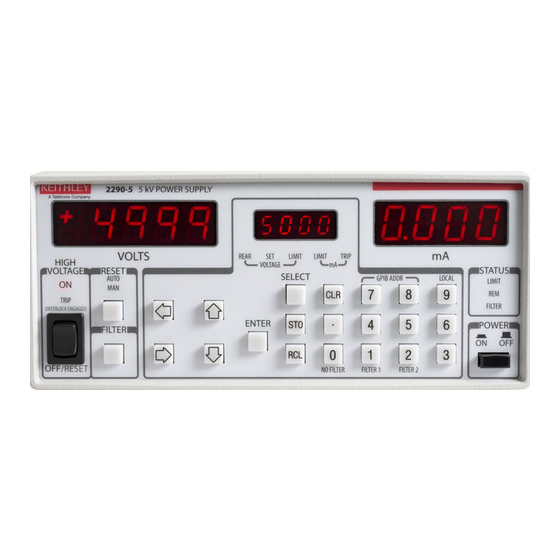
Section 1: Introduction Model 2290-5 5 kV Power Supply User's Manual Optional accessories The following optional accessories are available for use with the Model 2290-5: Connecting cables and connectors • Model 2290-5-SHV – SHV plug to SHV plug cable; 3.05 meters (10 feet). •... - Page 12 Model 2290-5 5 kV Power Supply User's Manual Section 1: Introduction POWER button Press the POWER button so that it is in the on position to turn the instrument on. Press the POWER button so that it is in the off position to turn it off.
-
Page 13: Rear-Panel Familiarization
Section 1: Introduction Model 2290-5 5 kV Power Supply User's Manual Rear-panel familiarization The Model 2290-5 rear panel is shown below. Descriptions of the controls on the rear panel follow the figure. Figure 2: Model 2290-5 rear panel Power entry The power entry module contains the line fuse, the line voltage selection, and includes filtering to block high-frequency noise from entering or exiting the unit. -
Page 14: Line Cord
Model 2290-5 5 kV Power Supply User's Manual Section 1: Introduction Line cord The Model 2290-5 uses a detachable, three-wire power cord for connection to the power source and to a safety earth ground through a grounded AC outlet. Only use the power cord that's provided with your instrument, or an equivalent adequately rated power cord. -
Page 15: Safe Configuration And Test Setup
Section 2 Safe configuration and test setup In this section: Introduction ................2-1 High voltage safety precautions ..........2-1 Safely connect to instruments ..........2-2 Interlock circuit ................. 2-2 Introduction The Model 2290-5 can generate hazardous voltages. It is intended for use with a test fixture or in a test system that has safety mechanisms in place to prevent an operator from accessing these voltages. -
Page 16: Safely Connect To Instruments
Section 2: Safe configuration and test setup Model 2290-5 5 kV Power Supply User's Manual Safely connect to instruments Line voltage selection There are three versions of the Model 2290-5 to allow operation from a 100, 120, 220, or 240 V nominal AC power source with a line frequency of 50 or 60 Hz. -
Page 17: Connecting The Interlock Of The Model 2290-5
Model 2290-5 5 kV Power Supply User's Manual Section 2: Safe configuration and test setup Connecting the interlock of the Model 2290-5 The interlock pins control the high-voltage supply. The pin locations and connections are shown in the following figure. The pins are: •... - Page 18 Section 2: Safe configuration and test setup Model 2290-5 5 kV Power Supply User's Manual Device connections Equipment used in the next figure: • 1 high-voltage diode enclosed in a safe test fixture • 1 Model 2290-5 high-voltage power supply •...
- Page 19 Model 2290-5 5 kV Power Supply User's Manual Section 2: Safe configuration and test setup Item Description Notes Model 2290-5-SHV high-voltage cable Model 2290-5-SHVBH high-voltage male bulkhead connector Test fixture protective earth (safety ground) Test fixture interlocked metal safety enclosure A safety enclosure with an interlock that has a normally open (NO) switch.
-
Page 20: Basic Operations
Section 3 Basic operations In this section: Numeric and cursor buttons ............. 3-1 Select, Enter, Clear ..............3-1 Output filter................3-2 Store and recall ................ 3-3 Analog programming and monitor ..........3-4 Set output voltage ..............3-6 Turn output on ................3-6 Set voltage limit ................ -
Page 21: Output Filter
Section 3: Basic operations Model 2290-5 5 kV Power Supply User's Manual Output filter The Model 2290-5 employs a switchable output filter for low noise performance. If higher slew rate or output power is required, the filter can be disabled. When the filter is enabled, the unit can reach either maximum voltage or maximum current but not both simultaneously. -
Page 22: Store And Recall
Model 2290-5 5 kV Power Supply User's Manual Section 3: Basic operations Store and recall STO (store) and RCL (recall) allow up to nine complete instrument setups to be saved in nonvolatile memory and later recalled. To store a setup: 1. -
Page 23: Analog Programming And Monitor
Section 3: Basic operations Model 2290-5 5 kV Power Supply User's Manual Analog programming and monitor The rear panel VOLTAGE select switch determines whether the output voltage is set from the front panel or from the rear panel SET/MON input. If the switch is in the MON (monitor) position, use the front panel controls. - Page 24 Model 2290-5 5 kV Power Supply User's Manual Section 3: Basic operations When the VOLTAGE switch is in the SET position, the REAR (rear panel) LED is on, and the output voltage is controlled by the rear panel signal and displayed on the center display when in the VOLTAGE SET mode.
-
Page 25: Set Output Voltage
Section 3: Basic operations Model 2290-5 5 kV Power Supply User's Manual Set output voltage To manually set the output voltage, with the high voltage on or off (refer to the Front-panel familiarization graphic for more information): 1. Press the SELECT button until the VOLTAGE SET LED is on. The present voltage setting will appear on the center display. -
Page 26: Set Current Limit
Model 2290-5 5 kV Power Supply User's Manual Section 3: Basic operations Set the voltage limit as follows: 1. Press the SELECT button until the VOLTAGE LIMIT LED is lit. The present value of the voltage limit is shown on the center display. 2. -
Page 27: Remote Operation
Section 4 Remote operation In this section: Introduction ................4-1 Command syntax ..............4-3 Remote commands ..............4-4 Introduction This section contains detailed information on remotely programming the Model 2290-5 over the IEEE- 488 (GPIB) interface. Any computer that supports the IEEE-488 bus may be used to program the instrument. - Page 28 Section 4: Remote operation Model 2290-5 5 kV Power Supply User's Manual To make a parallel connection to the instrument, stack the connectors. Each connector has two screws to ensure that connections remain secure. The figure below shows a typical connection diagram for a test system with multiple instrument .
-
Page 29: Set The Gpib Address
Model 2290-5 5 kV Power Supply User's Manual Section 4: Remote operation Set the GPIB address Before attempting to communicate with the Model 2290-5 over the IEEE-488 interface, make sure the instrument's primary address is set correctly. To enter the GPIB address mode, press both GPIB ADDR buttons simultaneously and then increment or decrement the address as required using the up and down arrow buttons. -
Page 30: Command Examples
Section 4: Remote operation Model 2290-5 5 kV Power Supply User's Manual Command examples Command Description VSET 1.0E3 Sets the voltage to 1000 V. VSET? Queries the voltage setting. *IDN? Queries the device identification. VSET 100.0;VSET? Sets the voltage to 100 V and queries the voltage. Remote commands The following Model 2290-5 commands are divided by the type of command: Output control, Setting control, Interface control, and Status reporting. -
Page 31: Setting Control Commands
Model 2290-5 5 kV Power Supply User's Manual Section 4: Remote operation VOUT? The VOUT? query returns the actual output voltage. This value is the same as that shown on the front panel VOLTS display. The value returned is a floating-point number and includes the positive sign of the output voltage. - Page 32 Section 4: Remote operation Model 2290-5 5 kV Power Supply User's Manual SMOD? The SMOD? query returns the VSET setting mode. A returned value of 0 indicates that the voltage value is controlled by the front panel or bus setting, while the value 1 indicates that the output is controlled by the rear panel SET/MON voltage control input.
-
Page 33: Interface Control Commands
Model 2290-5 5 kV Power Supply User's Manual Section 4: Remote operation FILT(?) <n> The FILT command controls the output filter, which is useful for reducing output ripple and noise. When <n> = 0 the output filter is disabled, while <n> = 1 and <n> = 2 enable Filter 1 and Filter 2, respectively. - Page 34 Section 4: Remote operation Model 2290-5 5 kV Power Supply User's Manual *ESE(?) <n> The *ESE common command sets the Standard Event Status Enable Register. The parameter <n> is the decimal value that programs the enable register. Example: *ESE 12 Set bits 2 and 3 *ESR? [<n>] The *ESR? common query reads the value of the Standard Event Status Register.
-
Page 35: Status Messages
Section 5 Status messages In this section: Status reporting ................ 5-1 Status reporting The Model 2290-5 reports on its status with two registers: the Status Byte Register and the Standard Event Status Register. The overall configuration of these registers is shown in the next figure. Note that bits 0, 1, and 8 through 15 of both the Standard Event Status Register and Standard Event Status Enable Register are not used in the Model 2290-5 and are always set to zero. -
Page 36: Status Byte Register
Section 5: Status messages Model 2290-5 5 kV Power Supply User's Manual Status byte register The next table summarizes bits in the Status Byte, which may be read with the *STB? query or with the serial polling sequence. The Model 2290-5 will generate a service request (SRQ) whenever one of these bits is set and the corresponding bit in the Service Request Enable Register is set, except for bit 6, the RQS/MSS bit. - Page 37 Model 2290-5 5 kV Power Supply User's Manual Section 5: Status messages Table: Standard event status register Decimal value Name Description Unused Unused Query Error Set by an output queue overflow. Recall Error Set if a stored configuration setting is corrupt. Execution Set by an out-of-range parameter, or non-completion of a command due to a condition such as an overload.
-
Page 38: Errors
Section 6 Errors In this section: Error and status messages ............6-1 Error and status messages Table: Error messages The next table shows the error numbers that you will see on the center display. These errors also set corresponding bits of the Standard Event Status Register. Note that the CLR button clears any errors. - Page 39 Section 6: Errors Model 2290-5 5 kV Power Supply User's Manual Table: Summarizes status messages The next table summarizes the status messages. Note that the message indicated in the next table is seen on the center display. Message Description VTRP Voltage trip (voltage limit exceeded) ITRP Current trip (current limit exceeded)
-
Page 40: Typical Applications
Section 7 Typical applications In this section: Introduction ................7-1 Program example 1 ..............7-1 Program example 2 ..............7-4 Introduction This section is broken into two examples: Example 1 demonstrates how to generate a basic linear voltage sweep with the Model 2290-5 to reverse bias a high voltage diode and make leakage current measurements at each point of the sweep. - Page 41 Section 7: Typical applications Model 2290-5 5 kV Power Supply User's Manual Device connections: The Model 2290-5 is a unipolar power supply. Therefore, the diode should be connected so that it can be reverse-biased, which means that the cathode should be connected to the HI output terminal of the Model 2290-5.
-
Page 42: Example Program Code
Model 2290-5 5 kV Power Supply User's Manual Section 7: Typical applications Example program code The following code was created and tested using the Python programming language using the pyVISA module. To learn more about Python, go to www.python.org. The example python program code below can be copied and pasted for your testing purposes, however, the code must match to include the indents of specific lines. -
Page 43: Program Example 2
Section 7: Typical applications Model 2290-5 5 kV Power Supply User's Manual Program example 2 Linear voltage sweep with Model 2290-5 and current measurements with Model 263xB The next figure shows how to connect the interlock circuits of the Model 2290-5 and Keithley Model 263xB SourceMeter instrument with the normally-open switch of the test fixture: Figure 13: Interfacing the interlocks of the Model 2290-10 and the Model 263xB SourceMeter Instrument to the test fixture... - Page 44 Model 2290-5 5 kV Power Supply User's Manual Section 7: Typical applications Device connections: In the next figure is a simple circuit schematic of the test performed in this example: Figure 14: Model 2290-5 reverse-biased diode with SourceMeter 2290-5-900-01 Rev. A/December 2013...
- Page 45 Section 7: Typical applications Model 2290-5 5 kV Power Supply User's Manual The next figures detail how these connections should be made in a safe test enclosure. Figure 15: Model 2290-5 reverse-biased diode connections with SourceMeter 2290-5-900-01 Rev. A/December 2013...
- Page 46 Model 2290-5 5 kV Power Supply User's Manual Section 7: Typical applications The following figure indicates pin connections for the lid interlock connections to Models 2290-5 and 263xB. Figure 16: Model 2290-5 reverse-biased diode interlock connections Item Description Notes Model 2290-5-SHV high-voltage cable Model 2290-5-SHVBH high-voltage male bulkhead connector Test fixture protective earth (safety ground)
-
Page 47: Example Program Code
Section 7: Typical applications Model 2290-5 5 kV Power Supply User's Manual Example program code The following code was created and tested using the Python programming language using the pyVISA module. To learn more about Python, go to www.python.org. The example python program code below can be copied and pasted for your testing purposes, however, the code must match yours to include the indents and spacing between lines. - Page 48 Model 2290-5 5 kV Power Supply User's Manual Section 7: Typical applications time.sleep(1) # Allow measurement to be taken currRdgList.append(currReading) voltage = voltage + 300 Set the voltage of the 2290 to 0V and turn off its output ki2290.write("VSET 0") ki2290.write("HVOF") Turn off the output of the Model 263xB ki263x.write("smua.source.output = smua.OUTPUT_OFF")
-
Page 49: Performance Verification
Section 8 Performance verification In this section: Introduction ................8-1 Environmental conditions ............8-1 Warm-up period ............... 8-1 Recommended test equipment ..........8-2 Verification procedures ............8-2 Introduction This section contains procedures to verify that the Model 2290-5 meets or exceeds its stated performance specifications for DC voltage accuracy, DC current accuracy, load regulation, and output voltage ripple. -
Page 50: Recommended Test Equipment
Section 8: Performance verification Model 2290-5 5 kV Power Supply User's Manual Recommended test equipment The next table summarizes the recommended test equipment for the verification procedures. Table: Recommended verification test equipment Equipment Specifications Manufacturer and model 1000:1 high-voltage 0.01% DC accuracy Ohm-Labs, Inc. -
Page 51: Dc Voltage Accuracy
Model 2290-5 5 kV Power Supply User's Manual Section 8: Performance verification DC voltage accuracy Use the following steps to measure the accuracy of the DC output voltage. 1. With the power off, connect the Model 2290-5 HIGH VOLTAGE output connector to the high voltage divider, and connect the multimeter to the 1V output tap of the divider (see next figure). - Page 52 Section 8: Performance verification Model 2290-5 5 kV Power Supply User's Manual Table: Filters off DC voltage accuracy Output volts Volts display limits Multimeter voltage reading limits 0.4975 0.5026 1000 1005 0.9974 1.0026 1500 1495 1505 1.4974 1.5027 2000 1995 2005 1.9973 2.0027...
-
Page 53: Dc Current Limit Accuracy
Model 2290-5 5 kV Power Supply User's Manual Section 8: Performance verification DC current limit accuracy The DC current accuracy test measures the accuracy of the output current limit and the mA (current) display. 1. Using the ohms function of the multimeter, measure and record the value of the 4.99 kΩ resistor. 2. - Page 54 Section 8: Performance verification Model 2290-5 5 kV Power Supply User's Manual 3. Turn on the power, and recall the Model 2290-5 default conditions. (Press RCL, 0, and then ENTER.) 4. Select the multimeter DCV function, and enable autoranging. 5. With the high voltage off, allow the multimeter reading to settle and then enable REL to null any residual offset voltage.
-
Page 55: Stuck Buttons
Section 9 Troubleshooting In this section: Stuck buttons ................9-1 Line power................9-1 Repeated trips ................9-1 Incorrect rear-panel output voltage .......... 9-2 Front-panel test ................ 9-2 Power-on reset ................. 9-2 No high voltage ................ 9-2 Service ..................9-3 Stuck buttons If the center display is filled with a number (such as 4444) or one particular message (such as Err2), and the front panel buttons are unresponsive, check to see if a button is stuck. -
Page 56: Incorrect Rear-Panel Output Voltage
Section 9: Troubleshooting Model 2290-5 5 kV Power Supply User's Manual Incorrect rear-panel output voltage If the output voltage is not correct, check the REAR LED and rear panel VOLTAGE Switch to verify the unit is in the SET mode. Also, check that the voltage limit is higher than the desired voltage. Front-panel test This test verifies that all segment drivers are functional. -
Page 57: Service
Model 2290-5 5 kV Power Supply User's Manual Section 9: Troubleshooting Service For repair and instrument adjustment services, contact your local Keithley Instruments representative. For worldwide contact numbers, visit the Keithley Instruments website (http://www.keithley.com). 2290-5-900-01 Rev. A/December 2013... - Page 58 All Keithley trademarks and trade names are the property of Keithley Instruments, Inc. All other trademarks and trade names are the property of their respective companies. Keithley Instruments, Inc. Corporate Headquarters 28775 Aurora Road Cleveland, Ohio 44139 440-248-0400 Fax: 440-248-6168 1-888-KEITHLEY www.keithley.com A Greater Measure of Confidence A Tektronix Company 7/13...
Need help?
Do you have a question about the Keithley 2290-5 and is the answer not in the manual?
Questions and answers