
Subscribe to Our Youtube Channel
Related Manuals for Tektronix KEITHLEY 2280 Series


Summary of Contents for Tektronix KEITHLEY 2280 Series
- Page 1 tek.com/keithley Series 2280 Precision Measurement DC Power Supplies Reference Manual 077085503 / March 2019 *P077085503* 077085503...
- Page 2 Series 2280 Precision DC Power Supply Reference Manual...
- Page 3 © 2019, Keithley Instruments, LLC Cleveland, Ohio, U.S.A. All rights reserved. Any unauthorized reproduction, photocopy, or use of the information herein, in whole or in part, without the prior written approval of Keithley Instruments, LLC, is strictly prohibited. These are the original instructions in English. All Keithley Instruments product names are trademarks or registered trademarks of Keithley Instruments, LLC.
-
Page 4: Safety Precautions
Safety precautions The following safety precautions should be observed before using this product and any associated instrumentation. Although some instruments and accessories would normally be used with nonhazardous voltages, there are situations where hazardous conditions may be present. This product is intended for use by personnel who recognize shock hazards and are familiar with the safety precautions required to avoid possible injury. - Page 5 For safety, instruments and accessories must be used in accordance with the operating instructions. If the instruments or accessories are used in a manner not specified in the operating instructions, the protection provided by the equipment may be impaired. Do not exceed the maximum signal levels of the instruments and accessories. Maximum signal levels are defined in the specifications and operating information and shown on the instrument panels, test fixture panels, and switching cards.
-
Page 6: Table Of Contents
Table of contents Introduction ......................1-1 Welcome ..........................1-1 Extended warranty ....................... 1-1 Contact information ......................1-1 Product documentation and drivers ..................1-2 Organization of manual sections ..................1-2 Key features ......................... 1-3 Standard accessories ......................1-4 Optional accessories ......................1-4 Available services ........................ - Page 7 Table of contents Series 2280 Precision DC Power Supply Reference Manual Overvoltage protection ......................2-78 Overcurrent protection ......................2-79 Overtemperature protection ....................2-80 Overprotection error ........................ 2-81 Maximum voltage limits ......................2-82 Saving setups ........................2-83 Save a user setup ........................2-83 Recall a user setup .........................
- Page 8 Series 2280 Precision DC Power Supply Reference Manual Table of contents List operation ........................3-34 Configuring a list ........................3-35 Importing a list from an external USB flash drive ..............3-37 Exporting a list to an external USB flash drive ................ 3-38 Configuring and running a list....................
- Page 9 Table of contents Series 2280 Precision DC Power Supply Reference Manual SCPI command reference ..................7-1 Common commands ......................7-1 *CLS ............................7-2 *ESE ............................7-3 *ESR? ............................7-4 *IDN? ............................7-4 *OPC ............................7-5 *LANG? ............................. 7-6 *RCL ............................7-6 *RST ............................
- Page 10 Series 2280 Precision DC Power Supply Reference Manual Table of contents :DISPlay:SCREen ........................7-49 :DISPlay:USER:TEXT[:DATA] ....................7-50 INITiate subsystem ......................7-51 :INITiate[n]:CONTinuous ......................7-51 :INITiate[n][:IMMediate] ......................7-52 MMEMory subsystem ......................7-52 :MMEMory:LOAD:SETup ......................7-52 :MMEMory:SAVE:SETup ......................7-53 OUTPut subsystem ......................7-54 :OUTPut:DELay:FALLing ......................
- Page 11 Table of contents Series 2280 Precision DC Power Supply Reference Manual :STATus:OPERation[:EVENt]? ....................7-100 :STATus:OPERation:ENABle ....................7-101 :STATus:OPERation:INSTrument[:EVENt]? ................. 7-101 :STATus:OPERation:INSTrument:ENABle ................7-102 :STATus:OPERation:INSTrument:ISUMmary[:EVENt]? ............7-103 :STATus:OPERation:INSTrument:ISUMmary:ENABle ............7-104 :STATus:OPERation:INSTrument:ISUMmary:CONDition? ........... 7-105 :STATus:PRESet ........................7-105 :STATus:QUEStionable[:EVENt]? ..................7-106 :STATus:QUEStionable:ENABle ................... 7-107 :STATus:QUEStionable:INSTrument[:EVENt]?..............
- Page 12 Series 2280 Precision DC Power Supply Reference Manual Table of contents :TRACe[n]:TRIGger:CURRent[:LEVel] .................. 7-144 :TRACe[n]:TRIGger:CURRent:STATe .................. 7-145 :TRACe[n]:TRIGger:OCCur? ....................7-146 :TRACe[n]:TRIGger:OFFSet ....................7-146 :TRACe[n]:TRIGger:VOLTage:DIRection ................7-147 :TRACe[n]:TRIGger:VOLTage[:LEVel] .................. 7-147 :TRACe[n]:TRIGger:VOLTage:STATe .................. 7-148 TRIGger subsystem ......................7-149 :TRIGger[:SEQuence[n]]:COUNt ................... 7-149 :TRIGger[:SEQuence[n]]:SAMPle:COUNt ................7-150 :TRIGger[:SEQuence[n]]:SOURce ..................
- Page 13 Table of contents Series 2280 Precision DC Power Supply Reference Manual Current noise at 20 MHz, 1 Ω load ..................B-16 Performance verification procedures ................. B-17 Performance verification conditions ..................B-17 Required equipment ........................ B-18 Check DC voltage setting readback accuracy with remote sense ........... B-18 Check DC voltage setting accuracy with remote sense ............
- Page 14 Series 2280 Precision DC Power Supply Reference Manual Table of contents Reading the registers ........................ D-6 Clearing the registers ......................D-6 Status byte and service request ................... D-7 Status Byte Register ......................... D-7 Service Request Enable Register ..................... D-9 Status register sets ......................D-9 Register bit descriptions ......................
-
Page 15: In This Section
Section 1 Introduction In this section: Welcome ...................1-1 Extended warranty ..............1-1 Contact information ..............1-1 Product documentation and drivers ..........1-2 Organization of manual sections ..........1-2 Key features ................1-3 Standard accessories ...............1-4 Optional accessories ..............1-4 Available services ..............1-5 General ratings .................1-5 Welcome Thank you for choosing a Keithley Instruments product. -
Page 16: Product Documentation And Drivers
Section 1: Introduction Series 2280 Precision DC Power Supply Reference Manual Product documentation and drivers The following documentation and drivers for the Series 2280 are available for download from the Keithley Instruments support website (tek.com/support). Quick Start Guide: Provides unpacking instructions, describes basic connections, reviews basic operation information, and provides a quick test procedure to ensure the instrument is operational. -
Page 17: Key Features
Series 2280 Precision DC Power Supply Reference Manual Section 1: Introduction Key features The Series 2280 has the following features: High current resolution and sensitivity to measure a wide range of load currents 6½-digit measurement resolution to enable a wide range of measurements while on one current range ... -
Page 18: Standard Accessories
Section 1: Introduction Series 2280 Precision DC Power Supply Reference Manual Standard accessories Accessory Part number Model 2280-001 Output Mating Connector 2280-001 Standard LAN crossover cable Quick start guide For details, see the following table. Certification of Calibration Varies You will get one of the following quick start guides. Languages Part number English... -
Page 19: Available Services
Series 2280 Precision DC Power Supply Reference Manual Section 1: Introduction Available services For the current list of available services and accessories, upgrades, and options for your instrument, visit tek.com/keithley. Service Model Number 1 additional year of factory warranty beyond the 3-Year factory 2280S-32-6-EW warranty (total of 4 years) 2280S-60-3-EW... -
Page 20: General Operation
Section 2 General operation In this section: Front-panel overview ..............2-1 Rear-panel overview ..............2-3 Front-panel user interface ............2-4 Installing the system ...............2-28 Test connections ..............2-37 Remote communications interfaces ........2-44 Set voltage and current limit............2-71 Select a measurement function ..........2-74 Select a specific measurement range ........2-75 Protection ................2-78 Saving setups .................2-82 Using the event log ..............2-85... - Page 21 Section 2: General operation Series 2280 Precision DC Power Supply Reference Manual Returns the display to the home screen. HOME key Opens the main menu. Select the icons using the navigation MENU key control and pressing the ENTER key to open source, measure, views, trigger, and system screens.
-
Page 22: Rear-Panel Overview
Series 2280 Precision DC Power Supply Reference Manual Section 2: General operation Illuminates when the instrument is controlled through a remote REMOTE LED interface. indicator Illuminates when the instrument is connected to a local area network LAN LED indicator (LAN). Positive, negative, and ground output binding posts for output Front-panel connections. -
Page 23: Front-Panel User Interface
Section 2: General operation Series 2280 Precision DC Power Supply Reference Manual The power module contains the AC line receptacle, the power line Power module fuse, and the line voltage selector switch. For safety precautions and other details, see Line fuse replacement (on page A-1) and Power the instrument on and off (on page 2-34). -
Page 24: Status And Error Indicators
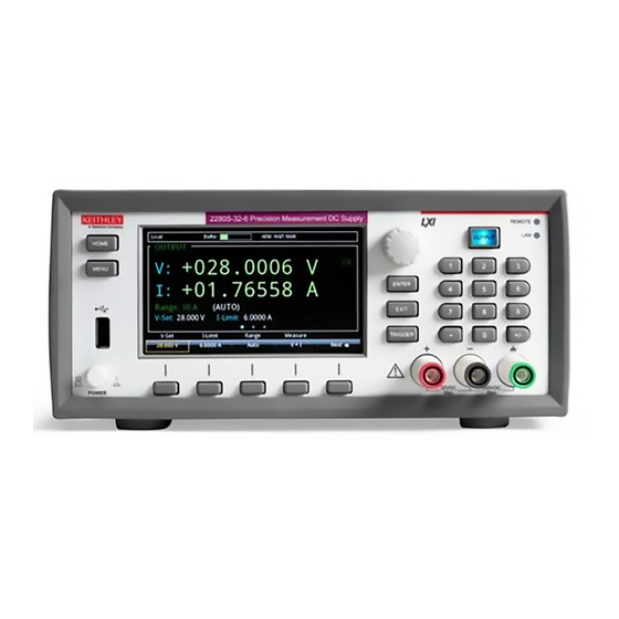
Series 2280 Precision DC Power Supply Reference Manual Section 2: General operation Figure 3: Power supply home screen Screen element Description System status and event indicators Located at the top of the home screen, these indicators provide information about the present state of the instrument. Some of the indicators open up a dialog box with more information or a settings menu when selected. -
Page 25: Communication Settings Status Indicator
Section 2: General operation Series 2280 Precision DC Power Supply Reference Manual Communication settings status indicator Move the focus to the communication indicator using the navigation control and press the ENTER key to see a list of present communications settings. Figure 4: Series 2280 communication status indicator Indicator Meaning... -
Page 26: Level Trigger Enabled Indicator
Series 2280 Precision DC Power Supply Reference Manual Section 2: General operation If a service request has been generated, SRQ is displayed to the right of the up and down arrows. You can configure the instrument to generate a service request (SRQ) when one or more errors or conditions occur. -
Page 27: Trigger Mode Settings Indicator
Section 2: General operation Series 2280 Precision DC Power Supply Reference Manual Trigger mode settings indicator This indicator shows the status of the trigger operation. Figure 7: Trigger indicator List and recall settings indicator This indicator shows the specified list number or recall settings. Figure 8: List and recall settings indicator 077085503 / March 2019... -
Page 28: Error And Event Indicator
Series 2280 Precision DC Power Supply Reference Manual Section 2: General operation Error and event indicator Move the focus to the error and event indicator using navigation control and press the ENTER key to see the present error and event messages. With the focus on the Event Log button, press ENTER to see the Error and Event Log. -
Page 29: Output View Area
Section 2: General operation Series 2280 Precision DC Power Supply Reference Manual OUTPUT view area This area displays the values for the present measurements and instrument status indicators. The following table lists the indicators shown on the right of the OUTPUT view area. Indicator Status description Output status... -
Page 30: Soft Key Area
Series 2280 Precision DC Power Supply Reference Manual Section 2: General operation Soft key area The Series 2280 display has multiple soft-key areas that you can access by pressing the NEXT soft key. The soft-key areas give you front-panel access to some instrument settings so that you can change, enable, or disable them quickly. - Page 31 Section 2: General operation Series 2280 Precision DC Power Supply Reference Manual Soft key area 2 Soft key area 2 contains the settings shown in the following figure and explained in the table. Figure 11: Soft key area 2 for power supply Setting Description Configure the safety settings using the numerical keys, soft keys, and...
- Page 32 Series 2280 Precision DC Power Supply Reference Manual Section 2: General operation Soft key area 3 Soft key area 3 contains the settings shown in the following figure and explained in the table. To change a setting, press the soft key to open a settings window. After configuration, close the window by pressing the ENTER or EXIT key.
-
Page 33: Menu Overview
Section 2: General operation Series 2280 Precision DC Power Supply Reference Manual Menu overview To access the main menu, press the MENU key on the Series 2280 front panel. The organization of the main menu is shown in the figure below. Figure 13: Power supply main menu The main menu is organized into five submenus, which are labeled in green across the top of the display. -
Page 34: Source Settings Menu
Series 2280 Precision DC Power Supply Reference Manual Section 2: General operation Source Settings menu You can change the following settings by pressing the MENU key, moving focus to the Source Settings icon, and pressing the Enter key. Setting Description Configure the voltage setting using the numerical keys, soft keys, and V-Set navigation control. -
Page 35: Source List Menu
Section 2: General operation Series 2280 Precision DC Power Supply Reference Manual Source List menu This menu allows you to set up a source configuration list. Setting Description Select a list from nonvolatile memory; import a list from an external USB flash List drive;... -
Page 36: Measure Menu
Series 2280 Precision DC Power Supply Reference Manual Section 2: General operation Measure menu The menus organized under Measure in the main menu allow you to select, configure, and perform measure operations from the Series 2280 front panel. The following topics describe the settings that are available on these interactive screens. -
Page 37: Measure Rel/Filter Menu
Section 2: General operation Series 2280 Precision DC Power Supply Reference Manual Measure Rel/Filter menu This menu contains settings that specify the way measurement information is returned. Setting Description Displays the presently selected function. Function Use the relative offset feature to subtract a set value or a baseline reading Rel State from measurement readings. -
Page 38: Measure Data Buffers Menu
Series 2280 Precision DC Power Supply Reference Manual Section 2: General operation Measure Data Buffers menu From this screen you can save, resize, and clear buffers. You also can set buffer fill mode and statistics functions. Setting Description Set the maximum number of readings the buffer can store (2 to 2,500). Note Size that when you resize a buffer, the readings contained in that buffer are cleared. -
Page 39: Views Menu
Section 2: General operation Series 2280 Precision DC Power Supply Reference Manual Views menu The menus organized under View in the main menu allow you to view the data plot, sheet, and statistics results on the Series 2280 front panel. The following topics describe the settings that are available on these interactive screens. -
Page 40: Trigger Menu
Series 2280 Precision DC Power Supply Reference Manual Section 2: General operation Trigger menu This menu allows you to configure triggering operations from the Series 2280 front panel. The following topics describe the settings that are available on these interactive screens. Trigger Configure menu This menu allows you to configure the triggering operations. -
Page 41: Trigger Digital In/Out Menu
Section 2: General operation Series 2280 Precision DC Power Supply Reference Manual Trigger Digital In/Out menu This menu allows you to configure the mode for each digital I/O line. The Series 2280 has 6 digital I/O lines (line 1 to line 6). For details, refer to Digital I/O (on page 3-19). -
Page 42: Level Trigger Menu
Series 2280 Precision DC Power Supply Reference Manual Section 2: General operation Level Trigger menu This menu allows you to configure a triggering condition to start to log the data in the data buffer during the test. You can set the triggering point based on the voltage or current. The triggering condition is based on whether the current or voltage rises or falls. -
Page 43: System Menu
Section 2: General operation Series 2280 Precision DC Power Supply Reference Manual You can use the following SCPI commands to configure the level trigger: :TRACe[n]:TRIGger:VOLTage:STATe :TRACe[n]:TRIGger:VOLTage[:LEVel] :TRACe[n]:TRIGger:VOLTage:DIRection :TRACe[n]:TRIGger:CURRent:STATe :TRACe[n]:TRIGger:CURRent[:LEVel] :TRACe[n]:TRIGger:CURRent:DIRection :TRACe[n]:TRIGger:OFFSet In addition, you can query whether any level trigger has been activated using the following SCPI command: :TRACe[n]:TRIGger:OCCUR? System menu... -
Page 44: System Settings Menu
Series 2280 Precision DC Power Supply Reference Manual Section 2: General operation System Settings menu This menu contains general instrument settings. Communication settings This menu allows you to configure GPIB, LAN, and USB communications settings. To access the System Communication settings screen: 1. -
Page 45: System Event Log Menu
Section 2: General operation Series 2280 Precision DC Power Supply Reference Manual Other system settings Setting Description Turn the instrument key-click sound on or off from this menu. Key Click You can set the front-panel display to dim after a period of time, or Backlight Timer you can set it so that it will never dim. -
Page 46: System Information Menu
Series 2280 Precision DC Power Supply Reference Manual Section 2: General operation System Information menu The System Information menu shows the serial number, firmware version, and the calibration adjust date and count. It also allows you to upgrade the firmware and calibrate the instrument. Setting Description When you select Demo mode, you can choose List Mode or Pulse. -
Page 47: Installing The System
Section 2: General operation Series 2280 Precision DC Power Supply Reference Manual To set the backlight timer from the front panel: 1. Press the MENU key. 2. Under System, select Settings. 3. Select the button next to Backlight Timer and press ENTER. The Backlight Timer dialog box opens. -
Page 48: Dimensions
Series 2280 Precision DC Power Supply Reference Manual Section 2: General operation Figure 15: Removing the front bumper Remove all connections to the rear panel of the Series 2280 before removing the rear bumper. 2. To remove the rear bumper, repeat the procedure in step 1. Dimensions The following figures show the mounting screw locations and the dimensions of the instrument with and without the bumpers. - Page 49 Section 2: General operation Series 2280 Precision DC Power Supply Reference Manual The following figures show the dimensions when the bumpers are installed. Figure 17: Series 2280 front and rear panel dimensions with bumpers 2-30 077085503 / March 2019...
- Page 50 Series 2280 Precision DC Power Supply Reference Manual Section 2: General operation Figure 18: Series 2280 top and side dimensions with bumpers 077085503 / March 2019 2-31...
- Page 51 Section 2: General operation Series 2280 Precision DC Power Supply Reference Manual The following figures show the dimensions when the bumpers have been removed. Figure 19: Series 2280 front and rear panel dimensions with bumpers removed 2-32 077085503 / March 2019...
- Page 52 Series 2280 Precision DC Power Supply Reference Manual Section 2: General operation Figure 20: Series 2280 top and side dimensions with bumpers removed 077085503 / March 2019 2-33...
-
Page 53: Power The Instrument On And Off
Section 2: General operation Series 2280 Precision DC Power Supply Reference Manual Power the instrument on and off Follow the procedure below to connect the Series 2280 to line power and turn on the instrument. The Series 2280 operates on the following ranges: 100 V, 120 V, 220 V, or 240 V at a frequency of 50 Hz or 60 Hz. -
Page 54: Turning The Series 2280 Output On
Series 2280 Precision DC Power Supply Reference Manual Section 2: General operation To connect the power cord: 1. Make sure that the front panel POWER switch is in the off (O) position. 2. Properly set the 100 V/120 V or 220 V/240 V selector switch located on the rear panel. 3. -
Page 55: Turning The Series 2280 Output Off
Section 2: General operation Series 2280 Precision DC Power Supply Reference Manual To turn the output on using a SCPI command: :OUTPut:STATe ON When you are using a remote interface to control the instrument and the output is turned off, pressing the OUTPUT switch cannot turn the output on. -
Page 56: Disable The Series 2280 Output
Series 2280 Precision DC Power Supply Reference Manual Section 2: General operation Disable the Series 2280 output You can disable the Series 2280 output from the front panel and by sending remote commands. If disabled, pressing the OUTPUT switch on the front panel does not turn on the output. Using the front panel: 1. -
Page 57: Front-Panel Connector
Section 2: General operation Series 2280 Precision DC Power Supply Reference Manual Front-panel connector Front-panel connectors are available to connect load wires for bench operation. A chassis ground binding post is also provided on the front panel. Figure 22: Front-panel binding post There are two locations on the binding post to connect the wire. -
Page 58: Rear-Panel Output Mating Connector
Series 2280 Precision DC Power Supply Reference Manual Section 2: General operation Rear-panel output mating connector Available connections on the rear output mating connector include the output high (+), output low (-), sense high (+), and sense low (-) terminals. The rear output terminals accept wire sizes from AWG 20 to AWG 12. -
Page 59: Four-Wire Sense Connection
Section 2: General operation Series 2280 Precision DC Power Supply Reference Manual Four-wire sense connection Using four-wire remote sensing connections ensures that the programmed voltage is applied to the load and compensates for the voltage drop in the leads between the power supply and the load. The maximum voltage drop is 1 V per lead. - Page 60 Series 2280 Precision DC Power Supply Reference Manual Section 2: General operation To reduce the environmental noise, load wires and sense wires must be twisted. For more information, refer to the following figure. Figure 26: Four-wire connection with twisted-pair wires Make sure you make the connections correctly.
-
Page 61: Open Leads Detection
Section 2: General operation Series 2280 Precision DC Power Supply Reference Manual Open leads detection When using four-wire sense connections, a missing or faulty connection with Sense HI, Sense LO, Output HI, or Output LO results in improperly regulated voltage and inaccurate voltage measurements. -
Page 62: Reversed Sense Leads
Series 2280 Precision DC Power Supply Reference Manual Section 2: General operation 5. Power on the instrument and repeat steps 1 through 3. The following figure shows the error that is displayed on the front panel. Figure 28: Open lead error You can retrieve the error number and message through a remote interface by sending the :SYSTem:ERRor? command. -
Page 63: Remote Communications Interfaces
Section 2: General operation Series 2280 Precision DC Power Supply Reference Manual Figure 29: Reversed sense leads error To clear the error, you need to clear the Questionable Instrument Summary Event Register bit and initiate the trigger model using the front panel or SCPI commands. For more information on registers, refer to Questionable Instrument Summary Event Register (on page D-16). -
Page 64: Supported Remote Interfaces
Series 2280 Precision DC Power Supply Reference Manual Section 2: General operation Supported remote interfaces The Series 2280 supports the following remote interfaces: GPIB: IEEE-488 instrumentation general purpose interface bus USB: Type B USB connection Ethernet: Local area network ethernet communications GPIB communications This topic contains information about GPIB standards, bus connections, and primary address selection. - Page 65 Section 2: General operation Series 2280 Precision DC Power Supply Reference Manual Figure 30: GPIB connector To allow many parallel connections to one instrument, stack the connectors. Each connector has two screws on it to ensure that connections remain secure. The figure below shows a typical connection diagram for a test system with multiple instruments.
-
Page 66: Set The Gpib Address
Series 2280 Precision DC Power Supply Reference Manual Section 2: General operation To connect the instrument to the GPIB: 1. Align the cable connector with the connector on the Series 2280 rear panel. The location of the connector is shown in the following figure. 2. -
Page 67: Lan Communications
Section 2: General operation Series 2280 Precision DC Power Supply Reference Manual The address is saved in nonvolatile memory, so it does not change when a reset is done or when the instrument power is turned off and then turned on again. To set the GPIB address from the front panel: 1. -
Page 68: One-To-One Connection
Series 2280 Precision DC Power Supply Reference Manual Section 2: General operation You can connect the instrument to the LAN in a one-to-one, one-to-many, two-network card, or enterprise configuration, as described in the following topics. One-to-one connection With most instruments, a one-to-one connection is done only when you are connecting a single instrument to a single network interface card. -
Page 69: Two Network Card Connection
Section 2: General operation Series 2280 Precision DC Power Supply Reference Manual Figure 35: One-to-many connection using a network hub or switch Two network card connection If you need to connect independent corporate and instrumentation networks, two network interface cards are required in the computer controller. Though the two networks are independent, stations on the corporate network can access the instruments, and the instruments can access the corporate network, using the same computer. -
Page 70: Instrumentation Connection To Enterprise Routers Or Servers
Series 2280 Precision DC Power Supply Reference Manual Section 2: General operation Instrumentation connection to enterprise routers or servers This connection uses an existing network infrastructure to connect instruments to the computer controller. In this case, you must get the network resources from the network administrator. Usually, the instruments are kept inside the corporate firewall, but the network administrator can assign resources that allow them to be outside the firewall. -
Page 71: Set Up Lan Communications On The Instrument
Section 2: General operation Series 2280 Precision DC Power Supply Reference Manual Set up LAN communications on the instrument This section describes how to set up manual or automatic LAN communications on the instrument. Check communication settings Before setting up the LAN configuration, you can check the communication settings on the instrument without making any changes. -
Page 72: Set Up Manual Lan Configuration
Series 2280 Precision DC Power Supply Reference Manual Section 2: General operation If you are using a Series 2280 with no front panel, you can configure the LAN using SCPI commands. For details, see the SCPI command :SYSTem:COMMunication:LAN:CONFigure page 7-114). Set up manual LAN configuration If necessary, you can set the IP address on the instrument manually. - Page 73 Section 2: General operation Series 2280 Precision DC Power Supply Reference Manual Set up LAN communications on the computer This section describes how to set up the LAN communications on your computer. Do not change your IP address without consulting your system administrator. Entering an incorrect IP address can prevent your computer from connecting to your corporate network.
-
Page 74: Web Interface Welcome Page
Series 2280 Precision DC Power Supply Reference Manual Section 2: General operation Web interface When the LAN and instrument establish a connection, you can open a web page for the instrument. To access the web interface: 1. Open a web browser on the host computer. 2. -
Page 75: Identify The Instrument
Section 2: General operation Series 2280 Precision DC Power Supply Reference Manual The welcome page of the web interface gives you basic information about the instrument, including: The instrument model, manufacturer, serial number, firmware revision, and the last LXI message An ID button to help you locate the instrument Links to the instrument web options, including administrative options and LXI information Identify the instrument... -
Page 76: Change The Web Interface Password
Series 2280 Precision DC Power Supply Reference Manual Section 2: General operation Figure 40: Modify IP configuration 4. Change the values. 5. Select Submit. The instrument reconfigures its settings, which may take a few seconds. You may lose your connection with the web interface after selecting Submit. This is normal and does not indicate an error or failure of the operation. -
Page 77: Take A Snapshot And Fetch Data In The Virtual Front Panel
Section 2: General operation Series 2280 Precision DC Power Supply Reference Manual Take a snapshot and fetch data in the virtual front panel You can take a snapshot of the Series 2280 LCD display and fetch buffered test data on the web page. - Page 78 Series 2280 Precision DC Power Supply Reference Manual Section 2: General operation To get buffered data: 1. From the navigation bar of the web interface home page, select Virtual Front Panel. 2. If you are prompted for a password, enter it and select Submit. The default password is admin. 3.
-
Page 79: Control The Instrument Through The Virtual Front-Panel Web Page
Section 2: General operation Series 2280 Precision DC Power Supply Reference Manual Control the instrument through the virtual front-panel web page You can operate the instrument using the virtual front panel shown in the figure below. Figure 43: Series 2280 LXI virtual front panel For more information about using the virtual front panel, refer to Front-panel user interface (on page... - Page 80 Series 2280 Precision DC Power Supply Reference Manual Section 2: General operation Figure 44: SCPI command web page 2. In the Command box, enter the SCPI command. You can enter a single command or batch commands, as shown in the figure. 3.
-
Page 81: Data Logging
Section 2: General operation Series 2280 Precision DC Power Supply Reference Manual Data logging You can save test data on the web interface to expand the data buffering. This function is useful when you monitor the device under test (DUT) for a long period. To log data on the web interface: 1. - Page 82 Series 2280 Precision DC Power Supply Reference Manual Section 2: General operation 3. If the data logging mode is set to Manual, select Stop on the right side of the screen to stop logging test data. If the mode is set to Time or Point, the logging will stop automatically when the time or point limit is reached.
-
Page 83: Usb Communications
Section 2: General operation Series 2280 Precision DC Power Supply Reference Manual Some of the fields in this pane are explained in the following table. Math, Relative, OXP, and Overflow settings visible in the table are saved in the instrument setup. You can save and recall special setups before using the data logging function;... -
Page 84: Using Usb
Series 2280 Precision DC Power Supply Reference Manual Section 2: General operation Using USB To communicate from a computer to the instrument you need a USB cable with a USB Type B connector end and a USB type A connector end. You need a separate USB cable for each instrument you plan to connect to the computer at the same time using the USB interface. - Page 85 Section 2: General operation Series 2280 Precision DC Power Supply Reference Manual To use the Keithley Configuration Panel to determine the VISA resource string: 1. Select Start > Programs > Keithley Instruments > Keithley Configuration Panel. The Select Operation dialog box is displayed. 2.
- Page 86 Series 2280 Precision DC Power Supply Reference Manual Section 2: General operation 4. Select USB. 5. Select Next. The Select Instrument Driver dialog box is displayed. Figure 48: Select Instrument Driver dialog box 6. Select Auto-detect Instrument Driver - Model. 7.
- Page 87 Section 2: General operation Series 2280 Precision DC Power Supply Reference Manual 8. Select Next. The Name Virtual Instrument dialog box is displayed. Figure 49: Name Virtual Instrument dialog box 9. In the Virtual Instrument Name box, enter a name that you want to use to refer to the instrument. 10.
- Page 88 If you have a full version of TEK-VISA on your system, you can run Openchoice Instrument Manager. See the Tektronix documentation for information. If you have the Keysight IO Libraries Suite on your system, you can run Keysight Connection Expert to check your USB instruments.
-
Page 89: How To Install The Keithley I/O Layer
Section 2: General operation Series 2280 Precision DC Power Supply Reference Manual How to install the Keithley I/O Layer Before installing, it is a good practice to check the Product Support web page (tek.com/product- support) to see if a later version of the Keithley I/O Layer is available. Search for Keithley I/O Layer. -
Page 90: Set Voltage And Current Limit
Series 2280 Precision DC Power Supply Reference Manual Section 2: General operation Set voltage and current limit Before you source voltage and current, you should specify a voltage and current limit. To configure the limit using the front-panel home screen: 1. -
Page 91: Constant Voltage (Cv) And Constant Current (Cc) Mode
Section 2: General operation Series 2280 Precision DC Power Supply Reference Manual Constant voltage (CV) and constant current (CC) mode The Series 2280 power supplies feature a constant voltage and constant current automatic crossover. This feature permits continuous operation in the transition from constant-voltage mode to constant- current mode as the load changes. - Page 92 Series 2280 Precision DC Power Supply Reference Manual Section 2: General operation Figure 52: Constant voltage mode Crossover from the constant-voltage mode to the constant-current mode also occurs automatically in response to an increase in load. For example, connect a 5 Ω resistor to the binding posts on the front panel, set the voltage to 25 V and current limit to 1.0 A, and turn on the output.
-
Page 93: Select A Measurement Function
Section 2: General operation Series 2280 Precision DC Power Supply Reference Manual You can use the :FORMat:ELEMents SCPI command to set the constant current or constant voltage mode. To set the constant current mode, send: :FORMat:ELEMents "MODE, CC" To set the constant voltage mode, send: :FORMat:ELEMents "MODE, CV"... -
Page 94: Select A Specific Measurement Range
Series 2280 Precision DC Power Supply Reference Manual Section 2: General operation Select a specific measurement range You can set specific measurement ranges or allow the instrument to choose the ranges automatically. The measurement range determines the full-scale input for the measurement. The measurement range also affects the accuracy of the measurements and the maximum signal that can be measured. - Page 95 Section 2: General operation Series 2280 Precision DC Power Supply Reference Manual To select a measurement range using the front-panel Measure Settings screen: 1. Press the MENU key. 2. Under Measure, select Settings. 3. Select the button next to Range. The Range dialog box is displayed. 4.
-
Page 96: Using Autoranging For Current Measurements
Series 2280 Precision DC Power Supply Reference Manual Section 2: General operation Using autoranging for current measurements When measurement autoranging is selected, the instrument automatically selects the best range to measure the signal. If the measurement reaches 120 percent of the present range (except for the 10 A range), the instrument changes the measurement range to the next higher range. -
Page 97: Protection
Section 2: General operation Series 2280 Precision DC Power Supply Reference Manual To set the current measurement range, send the command: :SENSe:CURRent:RANGe:AUTO ON To set the concurrent measurement range, send the command: :SENSe:CONCurrent:RANGe:AUTO ON You can set specific measurement ranges or allow the instrument to choose the ranges automatically. -
Page 98: Setting Overvoltage Protection Limits
Series 2280 Precision DC Power Supply Reference Manual Section 2: General operation Even with the overvoltage protection set to the lowest value, never touch anything connected to the terminals of the Series 2280 when the output is on. Always assume that a hazardous voltage (greater than 30 V RMS) is present when the output is on. -
Page 99: Setting Overcurrent Protection Limits
Section 2: General operation Series 2280 Precision DC Power Supply Reference Manual Even with the overcurrent protection set to the lowest value, never touch anything connected to the terminals of the Series 2280 when the output is on. Always assume that a hazardous voltage (greater than 30 V RMS) is present when the output is on. -
Page 100: Overprotection Error
Series 2280 Precision DC Power Supply Reference Manual Section 2: General operation If an overtemperature condition occurs, turn off the instrument and allow it to cool for 30 minutes. You cannot turn the output on until the instrument cools down. Verify that there is adequate ventilation. -
Page 101: Maximum Voltage Limits
Section 2: General operation Series 2280 Precision DC Power Supply Reference Manual To clear an overprotection error using the front panel: When the overprotection error dialog box is displayed, you can press the ENTER key to initiate the trigger model. To clear an overprotection error using a SCPI command: When an overprotection error occurs, send the following command to clear the register and initiate the trigger model:... -
Page 102: Saving Setups
Series 2280 Precision DC Power Supply Reference Manual Section 2: General operation Saving setups You can save the present settings that you have defined for the Series 2280 to internal memory. After the settings are saved, you can recall the settings. You can also set them to be the default settings on power up. -
Page 103: Recall A User Setup
Section 2: General operation Series 2280 Precision DC Power Supply Reference Manual To save a user setup to external USB flash drive using SCPI commands: Send the command: :MMEMory:SAVE:SETup "mysetup" Save the present setup to the external USB flash drive as mysetup. Recall a user setup You can recall setups from internal nonvolatile memory or external USB flash drive. -
Page 104: Specify A Default Setup
Series 2280 Precision DC Power Supply Reference Manual Section 2: General operation Specify a default setup You can specify a default setup that is applied immediately after the instrument is powered on. To save a default setup to internal nonvolatile memory from the front panel: 1. -
Page 105: Save The Event Log To An External Flash Drive
Section 2: General operation Series 2280 Precision DC Power Supply Reference Manual Save the event log to an external flash drive To save the event log to a USB flash drive from the front panel: 1. Press the MENU key. 2. -
Page 106: Instrument Sounds
Series 2280 Precision DC Power Supply Reference Manual Section 2: General operation To view system information using SCPI commands: To retrieve the manufacturer, model number, serial number, and firmware version, send the command: *IDN? To read the line frequency, send the command: SYStem:LFRequency? The firmware build, memory available, and calibration date are not available when using SCPI commands. -
Page 107: Reset The Instrument
Section 2: General operation Series 2280 Precision DC Power Supply Reference Manual The instrument also responds to other types of resets. These resets include: Password reset: This resets the instrument password to its default value. You can reset the password by pressing the MENU key and under System, selecting Settings > System Password. - Page 108 Series 2280 Precision DC Power Supply Reference Manual Section 2: General operation Math and statistics reset values Setting* Default value reset from Default value reset by the MENU > System > *RST (on page 7-7) Settings > Reset command or :SYSTem:PRESet page 7-124) command MENU >...
-
Page 109: Calibration Reset Values
Section 2: General operation Series 2280 Precision DC Power Supply Reference Manual Calibration reset values Setting* Default value reset from Default value reset by MENU > System > *RST (on page 7-7) Settings > Reset command or :SYSTem:PRESet page 7-124) command Not available from front panel :CALibration:PROTected:STATe (on page 7-... - Page 110 Series 2280 Precision DC Power Supply Reference Manual Section 2: General operation Format reset values Setting* Default value reset from Default value reset by MENU > System > Settings *RST (on page 7-7) > Reset command or :SYSTem:PRESet page 7-124) command "READ, SOUR, UNIT, Not available from front panel Not applicable...
-
Page 111: Measurement Reset Values
Section 2: General operation Series 2280 Precision DC Power Supply Reference Manual Measurement reset values Setting* Default value reset from Default value reset by the MENU > System > Settings *RST (on page 7-7) > Reset command or :SYSTem:PRESet page 7-124) command "CONC:DC"... -
Page 112: Source Reset Values
Series 2280 Precision DC Power Supply Reference Manual Section 2: General operation Source reset values Setting* Default value reset from Default value reset by the MENU > System > *RST (on page 7-7) Settings > Reset command or :SYSTem:PRESet (on page 7-124) command 0.1000 MENU >... -
Page 113: Status Model Reset Values
Section 2: General operation Series 2280 Precision DC Power Supply Reference Manual Status model reset values Setting* Default value reset from Default value MENU > System > reset by the *RST Settings > Reset (on page 7-7) command or :SYSTem:PRESet (on page 7-124) command —... -
Page 114: Trigger Reset Values
Series 2280 Precision DC Power Supply Reference Manual Section 2: General operation Trigger reset values Setting* Default value reset from Default value reset by the MENU > System > Settings > *RST (on page 7-7) Reset command or :SYSTem:PRESet page 7-124) command 0 (Off) MENU >... -
Page 115: In This Section
Section 3 Functions and features In this section: Instrument access ..............3-1 Graph ..................3-2 Output delay, slew rate, and source delay ........3-5 Data buffer ................3-8 Digital I/O ................3-19 Trigger model ................3-25 Level trigger ................3-29 List operation ................3-34 Sink operation .................3-50 Instrument access You can specify that the control interfaces request access before taking control of the instrument. -
Page 116: Changing The Password
Section 3: Functions and features Series 2280 Precision DC Power Supply Reference Manual Changing the password If the instrument is set to the access mode of All, you must enter a password to change to a new control interface. You can set the password, as described below. The default password is admin. -
Page 117: Changing The Window Position And Zoom
Series 2280 Precision DC Power Supply Reference Manual Section 3: Functions and features Changing the window position and zoom You can use window position and zoom to specify how the readings are displayed on the screen. Use window position to set the center point of graph. Use window zoom to specify the number of readings that can be displayed. -
Page 118: Adjusting The Scale And Offset Of The Y-Axis
Section 3: Functions and features Series 2280 Precision DC Power Supply Reference Manual Adjusting the scale and offset of the Y-axis You can adjust the scale and offset of Y-axis automatically or manually. When auto adjustment is enabled, the instrument automatically changes the scale and offset of Y-axis according to current and voltage measurements. -
Page 119: Output Delay, Slew Rate, And Source Delay
Series 2280 Precision DC Power Supply Reference Manual Section 3: Functions and features To set the manual adjustment on the front panel: 1. Press the MENU key. 2. Under Views, select Graph. 3. Select the button next to I Manual Adjust or V Manual Adjust and press ENTER. 4. -
Page 120: Output Delay
Section 3: Functions and features Series 2280 Precision DC Power Supply Reference Manual Output delay You can set a delay before turning on the output or turning off the output. The delay can range from 0.001 s to 10 s. Using the front panel: 1. -
Page 121: Setting The Source Delay
Series 2280 Precision DC Power Supply Reference Manual Section 3: Functions and features The slew rate ranges from 10 V per second to 1000 V per second. The slew rate setting works properly if the instrument operates below 5 V and 6 A. If it operates above these values, the instrument sources with a noise value of 50 Hz. -
Page 122: Data Buffer
Section 3: Functions and features Series 2280 Precision DC Power Supply Reference Manual Using SCPI commands: To set the source delay, set the command to a value. For example, to set the delay to 5 s, send: :DEL 5 To enable a source delay, send the command: :DEL:STAT ON Data buffer The data buffer captures measurements, instrument status, and the output state of the instrument. -
Page 123: Buffer Fill Status
Series 2280 Precision DC Power Supply Reference Manual Section 3: Functions and features Buffer fill status You can determine buffer fill status from the front panel. As shown in the following figure, the active buffer indicator displays buffer fill status. Figure 58: Buffer indicator Setting reading buffer size and buffer mode To configure the buffer, configure the following settings:... - Page 124 Section 3: Functions and features Series 2280 Precision DC Power Supply Reference Manual Buffer mode The buffer mode setting for the reading buffer controls how the incoming data is managed as the buffer fills. The options are: Never: The buffer stops accepting data. Next: The buffer stops accepting data once it fills to capacity and no new data is stored in the buffer.
- Page 125 Series 2280 Precision DC Power Supply Reference Manual Section 3: Functions and features Using the front panel to set fill mode: 1. Press the MENU key. 2. Under Measure, select Data Buffers. 3. Select the button next to Mode. The Mode screen is displayed. 4.
-
Page 126: Viewing And Saving Buffer Content
Section 3: Functions and features Series 2280 Precision DC Power Supply Reference Manual Viewing and saving buffer content You can view the content of the buffer from the front panel. However, the front panel may not be flexible enough for your particular type of data analysis. For further analysis, save the contents of the ®... - Page 127 Series 2280 Precision DC Power Supply Reference Manual Section 3: Functions and features The following table describes the information that is stored in each column of the spreadsheet. Heading Description Index Provides an identifier for each reading. Current The value saved in the buffer depends on the measurement function. For more information, see the following table.
- Page 128 Section 3: Functions and features Series 2280 Precision DC Power Supply Reference Manual To use the front panel to view the contents of the reading buffer: 1. Press the MENU key. 2. Under Views, select Sheet. 3. Select the button next to Data Sheet. The data is displayed. 4.
-
Page 129: Using The Front Panel To Save Buffer Content To Files
Series 2280 Precision DC Power Supply Reference Manual Section 3: Functions and features Using the front panel to save buffer content to files To use the front panel to save or append buffer content to files: 1. Insert a USB flash drive into the USB port. 2. -
Page 130: Specifying The Data In The Buffer To Perform With Statistics
Section 3: Functions and features Series 2280 Precision DC Power Supply Reference Manual Using the SCPI commands: :CALCulate2:FORMat <name> Where <name> can be any of the following options separated by commas: MINimum MAXimum MEAN SDEViation PKPK For example, you could enable minimum and maximum calculations by sending: :CALCulate2:FORMat MIN, MAX Specifying the data in the buffer to perform with statistics You must select either the voltage or current value in the buffer to perform statistics calculations. -
Page 131: Formatting The Statistical Results
Series 2280 Precision DC Power Supply Reference Manual Section 3: Functions and features For example, if you select Current as the statistics function and switch the screen to the Graph screen, a graph screen similar to the following is shown. Figure 61: Graph screen with statistics To specify the statistics function using SCPI commands: :CALCulate2:FUNCtion CURRent... -
Page 132: Using Scpi Commands To Save Buffer Content To Files
Section 3: Functions and features Series 2280 Precision DC Power Supply Reference Manual Using the SCPI commands: :CALCulate2:FORMat:ELEMents <item list> Where <item list> includes the following items: READing UNIT RNUMber TSTamp For example, select READ and TSTamp as returned elements by sending: :CALCulate2:FORMat:ELEMents "READing,TSTamp"... -
Page 133: Automatically Clearing A Buffer
Series 2280 Precision DC Power Supply Reference Manual Section 3: Functions and features Automatically clearing a buffer When using the power supply function, you can enable the autoclear function for the buffer. With autoclear enabled, the buffer is automatically cleared when the storage process starts. Using the front panel: 1. - Page 134 Section 3: Functions and features Series 2280 Precision DC Power Supply Reference Manual Figure 62: Digital I/O port Series 2280 digital I/O port pinouts Description I/O line 1 I/O line 2 I/O line 3 I/O line 4 line (relay flyback diode protection) I/O line 5 +5 V line I/O line 6...
-
Page 135: Digital I/O Lines
Series 2280 Precision DC Power Supply Reference Manual Section 3: Functions and features Digital I/O lines The following table describes the possible pin configurations for the digital line function and action. Line mode Available configurable lines Trigger in Line 1 Meter complete output Line 2 Fault output... - Page 136 Section 3: Functions and features Series 2280 Precision DC Power Supply Reference Manual Do not apply more than 50 mA (maximum current) or exceed +33 V (maximum voltage) on the digital I/O port. Applying current or voltage exceeding these limits may damage the instrument.
-
Page 137: Configuring Digital I/O Lines
Series 2280 Precision DC Power Supply Reference Manual Section 3: Functions and features +5 V line The digital I/O port provides a +5 V output. You can use this line to drive external logic circuitry. The maximum current output for this line is 500 mA (≥ 4.6 V). Configuring digital I/O lines You can use front panel or a remote interface to set up and control the digital I/O lines. -
Page 138: Using Scpi Commands To Configure Digital I/O Lines
Section 3: Functions and features Series 2280 Precision DC Power Supply Reference Manual Using SCPI commands to configure digital I/O lines Using SCPI commands to configure digital I/O lines: To set the line mode to the specified line, send the following command: :DIGital:LINE<n>:FUNCtion <function>... -
Page 139: Trigger Model
Series 2280 Precision DC Power Supply Reference Manual Section 3: Functions and features Trigger model The trigger model controls the sequence in which measurements occur. It consists of two layers (Arm Layer and Trigger Layer) to provide versatility. Programmable counters allow operations to be repeated, and various input and output trigger options are available to provide source-measure synchronization. -
Page 140: Idle And Initiate
Section 3: Functions and features Series 2280 Precision DC Power Supply Reference Manual Idle and initiate The instrument is in the idle state when it is not operating in the arm layer or trigger layer of the trigger model. When in the idle state, the instrument cannot perform any measurements. You can send the following commands to initiate the trigger model: :INITiate :INITiate:CONTinuous... -
Page 141: Source, Source Delay, And Measure Actions
Series 2280 Precision DC Power Supply Reference Manual Section 3: Functions and features Source, source delay, and measure actions The source-delay-measure (SDM) cycle consists of the following actions: Source: Programmed output current or voltage level changes are performed. It also performs the programmed slew rate during the level changes when the slew function is enabled. -
Page 142: Running The Trigger Model
Section 3: Functions and features Series 2280 Precision DC Power Supply Reference Manual Running the trigger model You can run the trigger model when the instrument is controlled either locally or remotely. If the instrument is being controlled locally, you can quickly configure the trigger model without setting up trigger source and trigger count in the trigger layer. - Page 143 Series 2280 Precision DC Power Supply Reference Manual Section 3: Functions and features If the instrument is controlled remotely, you can configure any of the parameters discussed above. If you change from remote to local control, the trigger model measurement method remains selected until you change it.
-
Page 144: Level Trigger
Section 3: Functions and features Series 2280 Precision DC Power Supply Reference Manual Level trigger You can configure a triggering condition to start logging data in the data buffer during the test. You can specify that the trigger execute when the voltage or current rises above or falls below a specified level. - Page 145 Series 2280 Precision DC Power Supply Reference Manual Section 3: Functions and features The following figure illustrates how the level trigger is activated when the voltage rises. Figure 67: Voltage level trigger (rise) 077085503 / March 2019 3-31...
-
Page 146: Configuring A Current Level Trigger
Section 3: Functions and features Series 2280 Precision DC Power Supply Reference Manual The following figure illustrates how the level trigger is activated when the voltage falls. Figure 68: Voltage level trigger (fall) Configuring a current level trigger To configure a current level trigger from the front panel: 1. - Page 147 Series 2280 Precision DC Power Supply Reference Manual Section 3: Functions and features 7. Select the button next to Current Direction and press the ENTER key. 8. Choose the direction for the trigger. 9. Select the button next to Offset and press the ENTER key. 10.
-
Page 148: List Operation
Section 3: Functions and features Series 2280 Precision DC Power Supply Reference Manual The following figure illustrates how the level trigger is activated when the current falls. Figure 70: Current level trigger (fall) List operation You can use lists to set up the instrument to source specific voltage and current values to a device under test (DUT). -
Page 149: Configuring A List
Series 2280 Precision DC Power Supply Reference Manual Section 3: Functions and features Configuring a list To set up a list from the front panel, select options from the SOURCE LIST screen. To configure a list on the front panel: 1. -
Page 150: Inserting Or Copying Points From The Front Panel
Section 3: Functions and features Series 2280 Precision DC Power Supply Reference Manual 7. After adding points to the list, select the Voltage box, Current box or Dwell box in the specified point row. Press the ENTER key. The editing window is displayed. You can use the numerical keys or the navigation control to change the value. -
Page 151: Importing A List From An External Usb Flash Drive
Series 2280 Precision DC Power Supply Reference Manual Section 3: Functions and features Importing a list from an external USB flash drive If you have created or saved a list file (.csv file), you can import the list from external USB flash drive. -
Page 152: Exporting A List To An External Usb Flash Drive
Section 3: Functions and features Series 2280 Precision DC Power Supply Reference Manual To import a list from the external USB flash drive using SCPI commands: :LIST:LOAD:USB <list number>,<filename> Where <list number> is the list number from 1 to 9 and <filename> is the filename that contains a name of the imported list. - Page 153 Series 2280 Precision DC Power Supply Reference Manual Section 3: Functions and features When you run a list, you cannot change the following settings from front panel or using SCPI commands. Sending the following commands causes an error 210, "Not permitted with list enabled." Source settings that cause an error Setting Front-panel operations...
- Page 154 Section 3: Functions and features Series 2280 Precision DC Power Supply Reference Manual Measure settings that cause an error Setting Front-panel operations SCPI commands Measurement :SENSe[n]:FUNCtion (on page 7-60) MENU > Measure function Settings > Function HOME > Measure ...
- Page 155 Series 2280 Precision DC Power Supply Reference Manual Section 3: Functions and features Data buffer settings that cause an error Setting Front-panel operations SCPI commands Buffer MENU > Data Buffers > :TRACe[n]:CLEar:AUTO or :DATA[n]:CLEar:AUTO Size (on page 7-135) ...
-
Page 156: Running A List
Section 3: Functions and features Series 2280 Precision DC Power Supply Reference Manual Running a list After configuring a list, you can run the list from the front panel. To run a list from the front panel: 1. Press the HOME key. 2. -
Page 157: List Triggering
Series 2280 Precision DC Power Supply Reference Manual Section 3: Functions and features List triggering You must configure list triggering before running a list. List triggering is similar to common triggering. However, list triggering introduces dwell time to control the source-delay-measure cycle. For more information about the common triggering, refer to Trigger model (on page 3-25). -
Page 158: List Running Time
Section 3: Functions and features Series 2280 Precision DC Power Supply Reference Manual List running time Depending on the hold time you select in the front-panel list options, there are two types of device actions during list running, shown in the following figures. Figure 73: Device action in time mode For list-running time in Time mode: Measurement time = Dwell - Source Delay... - Page 159 Series 2280 Precision DC Power Supply Reference Manual Section 3: Functions and features Figure 74: Device action in point mode For list-running time in Point mode: Measurement Time = Sample Count * Sample Speed The set dwell time is ignored. 077085503 / March 2019 3-45...
-
Page 160: Step Mode Triggering
Section 3: Functions and features Series 2280 Precision DC Power Supply Reference Manual Step mode triggering In step mode, the instrument generates a measure complete signal after each list step. You can detect this signal in digital I/O line 2. For details, refer to Digital I/O (on page 3-19). - Page 161 Series 2280 Precision DC Power Supply Reference Manual Section 3: Functions and features The following figure illustrates the process of measurement for step mode. Figure 76: Step mode measurement time When using immediate triggering, the instrument runs the next list step after sending the measure complete signal.
-
Page 162: Sweep Mode Triggering
Section 3: Functions and features Series 2280 Precision DC Power Supply Reference Manual Sweep mode triggering In sweep mode, the instrument generates a measure complete signal after each list cycle. You can detect this signal in digital I/O line 2. For details, refer to Digital I/O (on page 3-19). -
Page 163: Increasing The Speed Of A List
Series 2280 Precision DC Power Supply Reference Manual Section 3: Functions and features The following figure illustrates the process of measurement for sweep mode. Figure 78: Sweep mode measurement time Increasing the speed of a list To increase the speed of a list: Reduce the NPLC. -
Page 164: Sink Operation
Section 3: Functions and features Series 2280 Precision DC Power Supply Reference Manual Using the front panel: Press the HOME > List > Enable to stop the list. Using SCPI commands: :ABORt Sink operation When the Series 2280 is operating as a sink, current has opposite polarities and the instrument is dissipating power rather than sourcing it. -
Page 165: Measurement Optimization
Section 4 Measurement optimization In this section: Introduction ................4-1 Optimizing either measurement accuracy or speed ....4-1 Math calculations that you can apply to measurements ..4-11 Relative offset .................4-12 Displayed measurements............4-15 Introduction This section contains information that will help you get more useful measurement data and better instrument performance. -
Page 166: Resolution
Section 4: Measurement optimization Series 2280 Precision DC Power Supply Reference Manual Resolution You can specify a resolution to adjust the measurement accuracy and speed. Changing resolution affects NPLC, autozero, display digits, and average filter. For details, see the following table. Autozero state/ Display Resolution... -
Page 167: Setting Resolution
Series 2280 Precision DC Power Supply Reference Manual Section 4: Measurement optimization Setting resolution To set the resolution from the front panel: 1. Select the measurement function. The resolution setting will be applied to this function. For more information, you can refer to Select a measurement function (on page 2-74). - Page 168 Section 4: Measurement optimization Series 2280 Precision DC Power Supply Reference Manual Figure 80: Speed vs. noise characteristic After adjusting the speed, you may want to adjust the number of digits that are displayed for measurements. See Displayed digits (on page 4-6). To set the number of power line cycles (NPLCs) using the front panel: 1.
-
Page 169: Autozero Measurements
Series 2280 Precision DC Power Supply Reference Manual Section 4: Measurement optimization Autozero measurements To ensure the reading accuracy, the instrument must measure internal references corresponding to the zero low and gain high references. The time interval between reference updates is determined by the integration aperture that is used for each user and internal reference analog-to-digital converter (ADC) measurement. -
Page 170: Displayed Digits
Section 4: Measurement optimization Series 2280 Precision DC Power Supply Reference Manual To set autozero on or off using SCPI commands: :SYSTem:AZERo[:STATe] ON :SYSTem:AZERo[:STATe] OFF If autozero is enabled, all functions make internal reference measurements. If disabled, no functions make internal reference measurements. When you perform a fast low-current measurement, you can disable the autozero for better measurement speed. -
Page 171: Filtering Measurement Data
Series 2280 Precision DC Power Supply Reference Manual Section 4: Measurement optimization Setting the displayed digits using SCPI commands To set the number of displayed digits using SCPI commands: SENSe:VOLTage:DIGits <n> SENSe:CURRent:DIGits <n> SENSe:CONCurrent:DIGits <n> Where <n> is: 4 = 4.5 digit resolution 5 = 5.5 digit resolution 6 = 6.5 digit resolution Filtering measurement data... - Page 172 Section 4: Measurement optimization Series 2280 Precision DC Power Supply Reference Manual For example, if the filter size is four, the first measurement is copied to all four-stack locations. Therefore, (Reading1 + Reading1 + Reading1 + Reading1)/4. The display and remote interface update after first reading.
-
Page 173: Setting Up The Averaging Filter
Series 2280 Precision DC Power Supply Reference Manual Section 4: Measurement optimization Figure 81: Filter window When you select the concurrent measurement function, filter operations only apply to current measurements and do not affect voltage measurements. Setting up the averaging filter Using the front panel: 1. - Page 174 Section 4: Measurement optimization Series 2280 Precision DC Power Supply Reference Manual 6. For the Window, select one of the sizes. 7. Select HOME to return to the operating display. Once the filter type and count are set up, you can enable and disable the averaging filter from the home screen.
-
Page 175: Math Calculations That You Can Apply To Measurements
Series 2280 Precision DC Power Supply Reference Manual Section 4: Measurement optimization Math calculations that you can apply to measurements The Series 2280 supports mx+b built-in math calculations. Math calculations are applied to the input signal after filter and relative offset operations are completed. For more details on the order of operations, see Displayed measurements (on page 4-15). -
Page 176: Setting Mx+B Math Operations
Section 4: Measurement optimization Series 2280 Precision DC Power Supply Reference Manual Setting mx+b math operations From the front panel: 1. Select the measurement function. The math operations will be applied to this function. For more information, you can refer to Select a measurement function (on page 2-74). -
Page 177: Relative Offset
Series 2280 Precision DC Power Supply Reference Manual Section 4: Measurement optimization Relative offset When making measurements, you may want to subtract an offset value from a measurement. The relative offset feature subtracts a set value or a baseline reading from measurement readings. When you enable relative offset, all measurements are recorded as the difference between the actual measured value and the relative offset value. -
Page 178: Turning On The Relative Offset
Section 4: Measurement optimization Series 2280 Precision DC Power Supply Reference Manual Using SCPI commands: :SENSe:FUNCtion "VOLTage" :SENSe:VOLTage:REFerence <n> :SENSe:VOLTage:REFerence:STATe ON Where <n> is the amount of the offset. To set the relative offset for another function, replace VOLTage with CURRent or CONCurrent. Turning on the relative offset Using the front panel: 1. -
Page 179: Displayed Measurements
Series 2280 Precision DC Power Supply Reference Manual Section 4: Measurement optimization Before you automatically acquire a reference for relative offset, make sure that the trigger model is not in idle mode, set the arm and trigger source to immediate, and turn on the output. For more information about the trigger model, see Trigger model (on page 3-25). - Page 180 Section 4: Measurement optimization Series 2280 Precision DC Power Supply Reference Manual Figure 82: Data flow 4-16 077085503 / March 2019...
-
Page 181: Select The Source Of Readings
Series 2280 Precision DC Power Supply Reference Manual Section 4: Measurement optimization Select the source of readings You can select the source of readings saved to the buffer using the front panel or SCPI commands. Using the front panel: 1. Press the MENU key. 2. -
Page 182: Application Examples
Section 5 Application examples In this section: Simple voltage output and current measurement ......5-1 Configure and execute a 10-step linear list sweep ....5-3 Perform a fast current load measurement .........5-7 Simple voltage output and current measurement This example demonstrates how to configure a voltage output make a precision voltage and current measurement using the default instrument configuration. -
Page 183: Device Connections
Section 5: Application examples Series 2280 Precision DC Power Supply Reference Manual Figure 83: Series 2280 remote interface connections Device connections Connect the DUT (for this example, a 1 kΩ resistor) to the output binding posts on the front panel. For details, refer to Two-wire local sense connection (on page 2-39). - Page 184 Series 2280 Precision DC Power Supply Reference Manual Section 5: Application examples Figure 84: Voltage and current readback To set the voltage and current limit, send the following SCPI commands: *RST :VOLT 5 :CURR 1 :OUTP ON :INIT:CONT ON 077085503 / March 2019...
-
Page 185: Configure And Execute A 10-Step Linear List Sweep
Section 5: Application examples Series 2280 Precision DC Power Supply Reference Manual Configure and execute a 10-step linear list sweep This example demonstrates the steps to set up the power supply to output a linear list sweep from 1 V to 10 V in 1 V steps (default settings). Each step in the list sweep will dwell for 3 s. The list is stored in list location 1. -
Page 186: Configure A 10-Step Linear List Sweep
Series 2280 Precision DC Power Supply Reference Manual Section 5: Application examples Configure a 10-step linear list sweep To configure a list on the front panel: 1. Press the MENU key. 2. Under Source, highlight the List icon using either the navigation control or the soft keys. Press ENTER. -
Page 187: Execute A 10-Step Linear List Sweep
Section 5: Application examples Series 2280 Precision DC Power Supply Reference Manual To delete a row on the front panel: 1. Highlight the Points cell of the row you want to delete. 2. Press ENTER to select the cell row. 3. -
Page 188: Perform A Fast Current Load Measurement
The following example demonstrates how to configure the power supply to perform a fast current measurement initiated by an external trigger on digital line 1. Equipment required One Series 2280 power supply Dual-channel arbitrary function generator (Tektronix AFG3120C) Oscilloscope Resistors: 2.5 Ω and 20 Ω nMOSFET... -
Page 189: Device Connections
Figure 88: Series 2280 remote interface connections Device connections Use a Tektronix two-channel AFG (for example, AFG3102C or equivalent) to generate two synchronous pulse signals. One signal is used to control the on and off state of an nMOSFET. The other is used as the external triggering signal of the Series 2280. - Page 190 Series 2280 Precision DC Power Supply Reference Manual Section 5: Application examples Figure 89: Fast current measurements setup Connect the digital I/O pin 1 and pin 9 with the AFG output channel. For details on digital I/O, refer to Digital I/O (on page 3-19).
-
Page 191: Measure The Fast Current Load Changes
Section 5: Application examples Series 2280 Precision DC Power Supply Reference Manual Measure the fast current load changes To perform a fast current load measurement on the front panel: 1. Press the MENU key. 2. Under Measure, select Settings. 3. Select the button next to Function and press the ENTER key. The function dialog box is displayed. - Page 192 Series 2280 Precision DC Power Supply Reference Manual Section 5: Application examples 21. Press the OUTPUT switch to turn on the output. To view the current measurements on the front panel: 1. Press the MENU key. 2. Under Views, select Graph. You can view the current measurements. Figure 91: Graph view of load current When the resistive load is too large (for example, 32 MΩ), the settling time for the source increases.
- Page 193 Section 5: Application examples Series 2280 Precision DC Power Supply Reference Manual The following graphic shows the Tektronix oscilloscope plot of the generator pulse output and the load current. The green waveform shows the changes of load current and the yellow waveform shows the pulse output.
-
Page 194: Introduction To Scpi Commands
Section 6 Introduction to SCPI commands In this section: Introduction to SCPI ..............6-1 SCPI command programming notes .........6-2 Introduction to SCPI The Standard Commands for Programmable Instruments (SCPI) standard is a syntax and set of commands that is used to control test and measurement devices. The following information describes some basic SCPI command information and how SCPI is used with the Series 2280 and presented in the Series 2280 documentation. -
Page 195: Command Execution Rules
Section 6: Introduction to SCPI commands Series 2280 Precision DC Power Supply Reference Manual The examples above show commands that are sent individually. You can also group command messages when you send them to the instrument. To group a set of commands, separate them with semicolons. -
Page 196: Optional Command Words
Series 2280 Precision DC Power Supply Reference Manual Section 6: Introduction to SCPI commands For example, you can send the command :DISPlay:CLEar in any of the following formats: :DISPlay:CLEar :display:clear :DISP:CLE :disp:cle Optional command words If a command word is enclosed in brackets ([ ]), the command word is optional. Do not include the brackets if you send the optional command word to the instrument. -
Page 197: Scpi Parameters
Section 6: Introduction to SCPI commands Series 2280 Precision DC Power Supply Reference Manual If you send two query commands without reading the response from the first, and then attempt to read the second response, you may receive some data from the first response followed by the complete second response. -
Page 198: Using The Scpi Command Reference
Series 2280 Precision DC Power Supply Reference Manual Section 6: Introduction to SCPI commands Using the SCPI command reference The SCPI command reference contains detailed descriptions of each of the SCPI commands that you can use to control your instrument. Each command description is broken into several standard subsections. -
Page 199: Command Name And Summary Table
Section 6: Introduction to SCPI commands Series 2280 Precision DC Power Supply Reference Manual Command name and summary table Each instrument command description starts with the command name, followed by a table with relevant information for each command. Definitions for the numbered items below are listed following the figure. -
Page 200: Command Usage
Series 2280 Precision DC Power Supply Reference Manual Section 6: Introduction to SCPI commands Command usage The Usage section of the remote command listing shows how to properly structure the command. Each line in the Usage section is a separate variation of the command usage; all possible command usage options are shown here. -
Page 201: Example Section
Section 6: Introduction to SCPI commands Series 2280 Precision DC Power Supply Reference Manual Example section The Example section of the command description shows some simple examples of how the command can be used. Figure 97: SCPI command description example 1. -
Page 202: Scpi Command Reference
Section 7 SCPI command reference In this section: Common commands ..............7-1 :ABORt[n] ................7-11 :CONFigure[n]:<function> ............7-12 :FETCh[n]? ................7-13 :FORMat:ELEMents ..............7-14 :FORCe:TRIGger ..............7-15 :MEASure[n]:<function>? ............7-16 :READ[n]? ................7-18 ARM subsystem ..............7-18 CALCulate subsystem ............7-20 CALibration subsystem ............7-34 Digital subsystem ..............7-44 DISPlay subsystem ..............7-46 INITiate subsystem ..............7-51 MMEMory subsystem .............7-52 OUTPut subsystem ..............7-53... -
Page 203: Cls
Section 7: SCPI command reference Series 2280 Precision DC Power Supply Reference Manual Although the commands in this section are shown in uppercase, common commands are not case sensitive (you can use either uppercase or lowercase). *CLS This command clears the event registers and error queues. Type Affected by Where saved... -
Page 204: Ese
Series 2280 Precision DC Power Supply Reference Manual Section 7: SCPI command reference *ESE This command sets and queries bits in the Standard Event Status Enable Register. Type Affected by Where saved Default value Command and query Power cycle Not saved See Details Usage *ESE <n>... -
Page 205: Esr
Section 7: SCPI command reference Series 2280 Precision DC Power Supply Reference Manual *ESR? This command reads the contents of the Standard Event Status Register (SESR). Type Affected by Where saved Default value Query only Not applicable Not applicable Not applicable Usage *ESR? Details... -
Page 206: Opc
Series 2280 Precision DC Power Supply Reference Manual Section 7: SCPI command reference Example *IDN? Output: KEITHLEY INSTRUMENTS LLC,MODEL 2280S-32- 6,01234567,01.00 Also see System information (on page 2-86) *OPC This command sets the operation complete (OPC) bit after all pending commands, including overlapped commands, have been executed. -
Page 207: Lang
Section 7: SCPI command reference Series 2280 Precision DC Power Supply Reference Manual *LANG? This command determines which command set is used by the instrument. Type Affected by Where saved Default value Query only Not applicable Nonvolatile memory SCPI Usage *LANG? Details The only available remote command set is SCPI, which is an instrument-specific language built on... -
Page 208: Rst
Series 2280 Precision DC Power Supply Reference Manual Section 7: SCPI command reference *RST This command resets the instrument settings to their default values. Type Affected by Where saved Default value Command only Not applicable Not applicable Not applicable Usage *RST Details Returns the instrument to default settings, cancels all pending commands, and cancels the response... -
Page 209: Sre
Section 7: SCPI command reference Series 2280 Precision DC Power Supply Reference Manual *SRE This command sets and queries the bits of Status Request Enable Register. Type Affected by Where saved Default value Command and query Power cycle Not saved See Details Usage *SRE <n>... -
Page 210: Trg
Series 2280 Precision DC Power Supply Reference Manual Section 7: SCPI command reference Example *STB? Query the contents of the Status Byte Register. Output: This output indicates that the Status Byte Register contains the binary value 10010001. Also see Standard Event Register (on page D-10) Status model (on page D-1) -
Page 211: Tst
Section 7: SCPI command reference Series 2280 Precision DC Power Supply Reference Manual *TST? This command performs a complete self-test and returns the results. Type Affected by Where saved Default value Query only Not applicable Not applicable Usage *TST? Details Sending the command returns 0. -
Page 212: Abort[N]
Series 2280 Precision DC Power Supply Reference Manual Section 7: SCPI command reference The Series 2280 has the following overlapped commands: *TRG :INITiate :CALibration:PROTection:STEP1:DATA :CALibration:PROTection:STEP2:DATA :CALibration:PROTection:STEP3:DATA :CALibration:PROTection:STEP4:DATA :CALibration:PROTection:STEP5:DATA :CALibration:PROTection:STEP6:DATA :CALibration:PROTection:STEP7:DATA :CALibration:PROTection:STEP8:DATA Also see CALibration subsystem... -
Page 213: Configure[N]:
Section 7: SCPI command reference Series 2280 Precision DC Power Supply Reference Manual :CONFigure[n]:<function> This command configures the instrument to a specific setup for measurements. Type Affected by Where saved Default value Command only Recall settings Save settings See Details Instrument reset Power cycle Usage... -
Page 214: Fetch[N]
Series 2280 Precision DC Power Supply Reference Manual Section 7: SCPI command reference :FETCh[n]? This command reads the latest post-processed reading. Type Affected by Where saved Default value Query only Not applicable Not applicable Not applicable Usage :FETCh[n]? Channel number: For single-channel instruments, the value is 1 Details This command requests the latest post-processed reading. -
Page 215: Format:elements
Section 7: SCPI command reference Series 2280 Precision DC Power Supply Reference Manual :FORMat:ELEMents This command specifies or queries data elements to be included in the data string. Type Affected by Where saved Default value Command and query Recall settings Save settings READ, SOUR, UNIT, REL Instrument reset... -
Page 216: Force:trigger
Series 2280 Precision DC Power Supply Reference Manual Section 7: SCPI command reference Example :FORMat:ELEMents "READ,TST" Include reading and timestamp in the reading buffer, Example output: +8.034562E-03, 07/01/2013 19:21:36.2553 Also see :FETCh[n]? (on page 7-13) :MEASure[n]:<function>? (on page 7-16) :READ[n]? (on page 7-18) :FORCe:TRIGger This command bypasses the control source (Arm layer or Trigger layer) when you do not wish to wait for the... -
Page 217: Measure[N]:
Section 7: SCPI command reference Series 2280 Precision DC Power Supply Reference Manual :MEASure[n]:<function>? This command makes a measurement and returns the reading. Type Affected by Where saved Default value Query only Not applicable Not applicable Not applicable Usage :MEASure[n]:<function>? :MEASure[n]:<function>? <range>... - Page 218 Series 2280 Precision DC Power Supply Reference Manual Section 7: SCPI command reference If a different function is selected, sending this command changes the measurement function to the one specified by <function>. This function remains selected after the measurement is complete. When this command is sent, the following commands execute in the following order: ...
-
Page 219: Read[N]
Section 7: SCPI command reference Series 2280 Precision DC Power Supply Reference Manual :READ[n]? This query makes measurements and returns the first reading. Type Affected by Where saved Default value Query only Not applicable Not applicable Not applicable Usage :READ[n]? Channel number: For single-channel instruments, the value is 1 Details When this command is sent, the following commands execute in the order they are presented:... -
Page 220: Arm Subsystem
Series 2280 Precision DC Power Supply Reference Manual Section 7: SCPI command reference ARM subsystem The commands in this subsystem configure and control the trigger model for the arm layer. :ARM[:SEQuence[n]]:COUNt This command sets the number of times to repeat the Arm event. Type Affected by Where saved... -
Page 221: Arm[:Sequence[N]]:Source
Section 7: SCPI command reference Series 2280 Precision DC Power Supply Reference Manual :ARM[:SEQuence[n]]:SOURce This command selects the control source for the arm layer. Type Affected by Where saved Default value Command and query Recall settings Save settings Instrument reset Power cycle Usage :ARM[:SEQuence[n]]:SOURce <source>... -
Page 222: Calculate Subsystem
Series 2280 Precision DC Power Supply Reference Manual Section 7: SCPI command reference CALCulate subsystem The commands in this subsystem configure and control the math and statistic operations. :CALCulate[1]:<function>:FORMat This command specifies which math operation is performed on measurements. Type Affected by Where saved Default value... -
Page 223: Calculate[1]:
Section 7: SCPI command reference Series 2280 Precision DC Power Supply Reference Manual :CALCulate[1]:<function>:KMATh:MBFactor This command specifies the offset for the y = mx + b operation. Type Affected by Where saved Default value Command and query Recall settings Save settings Instrument reset Power cycle Usage...:Kmath:mbfactor -
Page 224: Calculate[1]:
Series 2280 Precision DC Power Supply Reference Manual Section 7: SCPI command reference Example :CALC:VOLT:FORM MXB Set the math function for voltage measurements to :CALC:VOLT:KMAT:MMF 0.80 mx+b. :CALC:VOLT:KMAT:MBF 50 Set the scale factor for voltage measurements to 0.80. :CALC:VOLT:KMAT:MUN 'C' Set the offset factor to 50.:Kmath:mmfactor - Page 225 Section 7: SCPI command reference Series 2280 Precision DC Power Supply Reference Manual The mx + b math operation lets you manipulate normal display readings (x) mathematically according to the following calculation: y = mx + b Where: y is the displayed result m is a user-defined constant for the scale factor x is the measurement reading (if you are using a relative offset, this is the measurement with relative offset applied)
-
Page 226: Calculate[1]:
Series 2280 Precision DC Power Supply Reference Manual Section 7: SCPI command reference :CALCulate[1]:<function>:KMATh:MUNits This command specifies the units suffix name for the y = mx + b math operation. Type Affected by Where saved Default value Command and query Recall settings Save settings Instrument reset...:Kmath:munits - Page 227 Section 7: SCPI command reference Series 2280 Precision DC Power Supply Reference Manual :CALCulate[1]:<function>:STATe This command enables or disables the math operations. Type Affected by Where saved Default value Command and query Recall settings Save settings 0 (OFF) Instrument reset Power cycle Usage :CALCulate[1]:<function>:STATe <state>[,<channel>]...
-
Page 228: Calculate2:Data
Series 2280 Precision DC Power Supply Reference Manual Section 7: SCPI command reference :CALCulate2:DATA? This command reads the results of specified statistics. Type Affected by Where saved Default value Query only Not applicable Not applicable Not applicable Usage :CALCulate2:DATA? :CALCulate2:DATA? <channel> <channel>... -
Page 229: Calculate2:Format
Section 7: SCPI command reference Series 2280 Precision DC Power Supply Reference Manual Example *RST Before the calculation, start the trigger model to take 10 :TRAC:CLE readings. :TRIG:COUN 10 :VOLT 6 The first CALC2:IMM? returns reading, units, timestamp :OUTP ON and reading number for MIN and MAX: :INIT 5.986128E+00V,06/25/2013... - Page 230 Series 2280 Precision DC Power Supply Reference Manual Section 7: SCPI command reference Details Use this command to select one or more available math formats. To use more than one format, separate each format with a comma (,). You can specify the statistic formats in any order. However, when more than one statistic formats are selected, CALC2:IMM? and CALC2:DATA? always return the data in the following order: MIN, MAX, MEAN, PKPK, and SDEV.
-
Page 231: Calculate2:Format:elements
Section 7: SCPI command reference Series 2280 Precision DC Power Supply Reference Manual :CALCulate2:FORMat:ELEMents This command specifies or queries data elements to be included in the data string. It only influences minimum and maximum query results. Type Affected by Where saved Default value Recall settings Save settings... -
Page 232: Calculate2:Function
Series 2280 Precision DC Power Supply Reference Manual Section 7: SCPI command reference Example *RST Before the calculation, start the trigger model to take 10 :TRAC:CLE readings. :TRIG:COUN 10 :VOLT 6 The first CALC2:IMM? returns reading, units, timestamp :OUTP ON and reading number for MIN and MAX: :INIT 5.986128E+00V,06/25/2013... -
Page 233: Calculate2:Immediate
Section 7: SCPI command reference Series 2280 Precision DC Power Supply Reference Manual Example *RST Before the calculation, start the trigger model to take 10 :TRAC:CLE readings. :TRIG:COUN 10 :VOLT 6 The first CALC2:IMM? returns reading, units, timestamp :OUTP ON and reading number for MIN and MAX: :INIT 5.986128E+00V,06/25/2013... - Page 234 Series 2280 Precision DC Power Supply Reference Manual Section 7: SCPI command reference When the statistics operations are disabled, sending this command will not perform the statistic operations. However, it will return the last calculation results. If the specified statistics calculations have never been performed, the instrument returns -1.000000E+37.
-
Page 235: Calculate2:State
Section 7: SCPI command reference Series 2280 Precision DC Power Supply Reference Manual :CALCulate2:STATe This command enables or disables the statistic calculations. Type Affected by Where saved Default value Command and query Recall settings Save settings 0 (OFF) Instrument reset Power cycle Usage :CALCulate2:STATe <state>... -
Page 236: Calibration Subsystem
Series 2280 Precision DC Power Supply Reference Manual Section 7: SCPI command reference CALibration subsystem The commands in this subsystem configure and control the calibration operations. :CALibration:PROTected:CANCel This command cancels the calibration procedures and drops the new constants. Affected by Where saved Default value Type... -
Page 237: Calibration:protected:code
Section 7: SCPI command reference Series 2280 Precision DC Power Supply Reference Manual :CALibration:PROTected:CODE This command changes the calibration password. Type Affected by Where saved Default value Command only Recall settings Nonvolatile memory 'KI002280' Usage :CALibration:PROTected:CODE <string> <string> Calibration password: An 8-character string including letters and numbers. Details Before changing the password, you must first enable calibration mode by using the following command:... -
Page 238: Calibration:protected:data
Series 2280 Precision DC Power Supply Reference Manual Section 7: SCPI command reference :CALibration:PROTected:DATA? This command queries the saved calibration constants. Type Affected by Where saved Default value Query only Not applicable Nonvolatile memory Not applicable Usage :CALibration:PROTected:DATA? Details For details, refer to Calibration constants (on page C-25). -
Page 239: Calibration:protected:date
Section 7: SCPI command reference Series 2280 Precision DC Power Supply Reference Manual :CALibration:PROTected:DATE This command specifies the calibration date. Type Affected by Where saved Default value Command and query Not applicable Nonvolatile memory Not applicable Usage :CALibration:PROTected:DATE <year>,<month>,<day> :CALibration:PROTected:DATE? <year>... -
Page 240: Calibration:protected[:Dc[N]]:Step
Series 2280 Precision DC Power Supply Reference Manual Section 7: SCPI command reference :CALibration:PROTected[:DC[n]]:STEP<step> This command performs the calibration procedures. Type Affected by Where saved Default value Command only Not applicable Not applicable Not applicable Usage :CALibration:PROTected[:DC[n]]:STEP1 :CALibration:PROTected[:DC[n]]:STEP2 :CALibration:PROTected[:DC[n]]:STEP3 :CALibration:PROTected[:DC[n]]:STEP4 :CALibration:PROTected[:DC[n]]:STEP5 :CALibration:PROTected[:DC[n]]:STEP6 :CALibration:PROTected[:DC[n]]:STEP7... - Page 241 Section 7: SCPI command reference Series 2280 Precision DC Power Supply Reference Manual Example :CAL:PROT:STAT ON, 'KI002280' Enable the calibration mode. :CAL:PROT:STEP1 Start voltage DAC and ADC zero-calibration point. :CAL:PROT:STEP1:DATA Enter the voltage reading from the external DMM. 0.2996 *OPC? Wait until step 1 finishes.
-
Page 242: Calibration:protected[:Dc[N]]:Step
Series 2280 Precision DC Power Supply Reference Manual Section 7: SCPI command reference Also see :CALibration:PROTected[:DC[n]]:STEP<step>:DATA (on page 7-41) :CALibration:PROTected:SAVE (on page 7-43) :CALibration:PROTected:STATe (on page 7-44) :CALibration:PROTected[:DC[n]]:STEP<step>:DATA This command enters the values for calibration calculations. Type Affected by Where saved Default value Command only Not applicable...:Data - Page 243 Section 7: SCPI command reference Series 2280 Precision DC Power Supply Reference Manual Example :CAL:PROT:STAT ON, "KI002280" Enable the calibration mode. :CAL:PROT:STEP1 Start voltage DAC and ADC zero-calibration point. :CAL:PROT:STEP1:DATA 0.2996 Enter the voltage reading from the external DMM. *OPC? Wait until step 1 finishes.
-
Page 244: Calibration:protected:save
Series 2280 Precision DC Power Supply Reference Manual Section 7: SCPI command reference :CALibration:PROTected:SAVE This command saves the calibration to nonvolatile memory after the calibration procedure has been completed. Affected by Where saved Default value Type Command only Not applicable Nonvolatile memory Not applicable Usage... -
Page 245: Calibration:protected:state
Section 7: SCPI command reference Series 2280 Precision DC Power Supply Reference Manual :CALibration:PROTected:STATe This command enables or disables calibration procedures when performing these procedures over the remote interface. Type Affected by Where saved Default value Instrument reset Command and query Not saved 0 (OFF) Power cycle... -
Page 246: Digital Subsystem
Series 2280 Precision DC Power Supply Reference Manual Section 7: SCPI command reference Digital subsystem The commands in the DIGital subsystem control the digital I/O lines. :DIGital:LINE<n>:FUNCtion This command sets the digital I/O pin to be a digital line and sets the pin to be input or output. Type Affected by Where saved... -
Page 247: Digital:line
Section 7: SCPI command reference Series 2280 Precision DC Power Supply Reference Manual :DIGital:LINE<n>:MANual:INPut:DATA? This command reads the data from manual input to the digital I/O pin. Type Affected by Where saved Default value Query only Not applicable Not applicable Not applicable Usage :DIGital:LINE<n>:MANual:INPut:DATA?:Manual:input:data -
Page 248: Display Subsystem
Series 2280 Precision DC Power Supply Reference Manual Section 7: SCPI command reference DISPlay subsystem This subsystem contains commands that control the front-panel display. :DISPlay:BRIGhtness This command sets and queries the brightness of the front-panel display. Type Affected by Where saved Default value Command and query Not applicable... -
Page 249: Display:clear
Section 7: SCPI command reference Series 2280 Precision DC Power Supply Reference Manual :DISPlay:CLEar This command removes user-defined text messages from the OUTPUT view screen. Type Affected by Where saved Default value Command only Not applicable Not applicable Not applicable Usage :DISPlay:CLEar [<channel>] <channel>... -
Page 250: Display:screen
Series 2280 Precision DC Power Supply Reference Manual Section 7: SCPI command reference :DISPlay:SCREen This command specifies which screen is displayed on the front-panel. Type Affected by Where saved Default value Command only Power cycle Not applicable Not applicable Usage :DISPlay:SCREen <screenName>... -
Page 251: Display:user:text[:Data]
Section 7: SCPI command reference Series 2280 Precision DC Power Supply Reference Manual :DISPlay:USER:TEXT[:DATA] This command defines the text that is displayed on the front-panel OUTPUT view screen. Type Affected by Where saved Default value Command only Power cycle Not applicable Not applicable Usage :DISPlay:USER:TEXT[:DATA] <string>[,<channel>]... -
Page 252: Initiate Subsystem
Series 2280 Precision DC Power Supply Reference Manual Section 7: SCPI command reference INITiate subsystem The commands in the INITiate subsystem control the trigger model. :INITiate[n]:CONTinuous This command enables and disables continuous triggering. Type Affected by Where saved Default value Recall settings Command and query Save settings... -
Page 253: Initiate[N][:Immediate]
Section 7: SCPI command reference Series 2280 Precision DC Power Supply Reference Manual :INITiate[n][:IMMediate] This command starts the trigger model. Type Affected by Where saved Default value Command only Not applicable Not applicable Not applicable Usage :INITiate[n][:IMMediate] Channel number: For single-channel instruments, the value is 1 Also see Trigger model (on page 3-25) -
Page 254: Mmemory:save:setup
Series 2280 Precision DC Power Supply Reference Manual Section 7: SCPI command reference Example :MMEMory:LOAD:SETup "mysetup" Recall the setup named mysetup in the external USB flash drive to the instrument. Also see :MMEMory:SAVE:SETup (on page 7-53) *RCL (on page 7-6) *SAV (on page 7-7) :MMEMory:SAVE:SETup... -
Page 255: Output Subsystem
Section 7: SCPI command reference Series 2280 Precision DC Power Supply Reference Manual OUTPut subsystem The output subsystem provides information and settings that control the source output. :OUTPut:DELay:FALLing This command specifies a delay that the instrument waits before turning off the specified output. Type Affected by Where saved... -
Page 256: Output:delay:rising
Series 2280 Precision DC Power Supply Reference Manual Section 7: SCPI command reference :OUTPut:DELay:RISing This command specifies the delay time that the instrument waits before turning on the specified output. Type Affected by Where saved Default value Command and query Recall settings Save settings Instrument reset... -
Page 257: Output:delay:state
Section 7: SCPI command reference Series 2280 Precision DC Power Supply Reference Manual :OUTPut:DELay:STATe This command enables and disables the delay time that the instrument waits before enabling and disabling the specified output. Type Affected by Where saved Default value Recall settings Command and query Save settings... -
Page 258: Output:protection:clear
Series 2280 Precision DC Power Supply Reference Manual Section 7: SCPI command reference :OUTPut:PROTection:CLEar This command clears the overvoltage, overcurrent, overtemperature, or reverse fault status. Type Affected by Where saved Default value Command only Not applicable Not applicable Not applicable Usage :OUTPut:PROTection:CLEar :OUTPut:PROTection:CLEar <channel>... -
Page 259: Output:protection:tripped?[
Section 7: SCPI command reference Series 2280 Precision DC Power Supply Reference Manual :OUTPut:PROTection:TRIPped?[<channel>] This command queries whether overvoltage, overcurrent, overtemperature, or reverse fault protection has been tripped. Type Affected by Where saved Default value Query only Not applicable Not applicable Not applicable Usage :OUTPut:PROTection:TRIPped?] -
Page 260: Output[:State]
Series 2280 Precision DC Power Supply Reference Manual Section 7: SCPI command reference :OUTPut[:STATe] This command enables or disables the source output. Type Affected by Where saved Default value Command and query Recall settings Save settings 0 (OFF) Instrument reset Power cycle Usage :OUTPut[:STATe] <state>... -
Page 261: Sense Subsystem
Section 7: SCPI command reference Series 2280 Precision DC Power Supply Reference Manual SENSe subsystem The SENSe subsystem commands configure and control the measurement functions of the Series 2280. Many of these commands are set for a specific function (concurrent, current, or voltage). For example, you can program a range setting for each function. -
Page 262: Sense[N]:
Series 2280 Precision DC Power Supply Reference Manual Section 7: SCPI command reference :SENSe[n]:<function>:AVERage:COUNt This command sets the number of measurements that are averaged when filtering is enabled for the specified function. Type Affected by Where saved Default value Recall settings Save settings Command and query Instrument reset...:Average:count -
Page 263: Sense[N]:
Section 7: SCPI command reference Series 2280 Precision DC Power Supply Reference Manual :SENSe[n]:<function>:AVERage[:STATe] This command enables or disables the averaging filter for measurements of the selected function. Type Affected by Where saved Default value Command and query Recall settings Save settings 1 (ON) Instrument reset...:Average[:State] -
Page 264: Sense[N]:
Series 2280 Precision DC Power Supply Reference Manual Section 7: SCPI command reference :SENSe[n]:<function>:AVERage:TCONtrol This command sets the type of averaging filter that is used for measurements for the selected function when the measurement filter is enabled. Type Affected by Where saved Default value Recall settings...:Average:tcontrol -
Page 265: Sense[N]:
Section 7: SCPI command reference Series 2280 Precision DC Power Supply Reference Manual :SENSe[n]:<function>:AVERage:WINDow This command specifies a filter window to control filter threshold. Type Affected by Where saved Default value Command and query Recall settings Save settings Instrument reset Power cycle Usage :SENSe[n]:<function>:AVERage:WINDow <value>...:Average:window -
Page 266: Sense[N]:
Series 2280 Precision DC Power Supply Reference Manual Section 7: SCPI command reference :SENSe[n]:<function>:DIGits This command determines the number of digits that are displayed for measurements on the front panel. Type Affected by Where saved Default value Command and query Recall settings Save settings Instrument reset...:Digits -
Page 267: Sense[N]:
Section 7: SCPI command reference Series 2280 Precision DC Power Supply Reference Manual :SENSe[n]:<function>:NPLCycles This command sets the time that the input signal is measured for measurements of the selected function. Type Affected by Where saved Default value Command and query Recall settings Save settings Instrument reset...:Nplcycles -
Page 268: Sense[N]:
Series 2280 Precision DC Power Supply Reference Manual Section 7: SCPI command reference :SENSe[n]:<function>:RANGe This command sets the measurement range for measurements of the selected function. Type Affected by Where saved Default value Command and query Power cycle Save settings Concurrent: 10 mA Current: 10 mA Voltage: 33 V for Model 2280S-...:Range - Page 269 Section 7: SCPI command reference Series 2280 Precision DC Power Supply Reference Manual When you read this setting, you see the measurement range that the instrument is presently using. If you change the range while the output is off, the instrument does not update the hardware settings, but if you read the range setting, the return is the setting that will be used when the output is turned on.
-
Page 270: Sense[N]:
Series 2280 Precision DC Power Supply Reference Manual Section 7: SCPI command reference :SENSe[n]:<function>:RANGe:AUTO This command determines if the range for measurements of the selected function is selected manually or automatically. Type Affected by Where saved Default value Command and query Recall settings Saved setup 1 (ON):Range:auto -
Page 271: Sense[N]:
Section 7: SCPI command reference Series 2280 Precision DC Power Supply Reference Manual :SENSe[n]:<function>:REFerence This command specifies the relative offset value for the measurement. Type Affected by Where saved Default value Command and query Recall settings Save settings Instrument reset Power cycle Usage :SENSe[n]:CONCurrent:REFerence <ref>...:Reference -
Page 272: Sense[N]:
Series 2280 Precision DC Power Supply Reference Manual Section 7: SCPI command reference :SENSe[n]:<function>:REFerence:ACQuire This command acquires a measurement and stores it as the relative offset value. Type Affected by Where saved Default value Command only Not applicable Not applicable Not applicable Usage :SENSe[n]:<function>:REFerence:ACQuire...:Reference:acquire -
Page 273: Sense[N]:
Section 7: SCPI command reference Series 2280 Precision DC Power Supply Reference Manual :SENSe[n]:<function>:REFerence:STATe This command enables or disables a relative offset value. Type Affected by Where saved Default value Command and query Recall settings Save settings 0 (OFF) Instrument reset Power cycle Usage :SENSe[n]:<function>:REFerence:STATe <state>...:Reference:state -
Page 274: Sense[N]:
Series 2280 Precision DC Power Supply Reference Manual Section 7: SCPI command reference :SENSe[n]:<function>:RESolution This command sets the measurement resolution for the selected measurement function. Type Affected by Where saved Default value Command only Recall settings Save settings Instrument reset Power cycle Usage :SENSe[n]:<function>:RESolution <value>...:Resolution -
Page 275: Source Subsystem
Section 7: SCPI command reference Series 2280 Precision DC Power Supply Reference Manual SOURce subsystem The commands in the SOURce subsystem configure and control the current source and voltage source. [:SOURce[n]]:DELay This command sets the source delay. Type Affected by Where saved Default value Command and query... -
Page 276: [:Source[N]]:Delay:state
Series 2280 Precision DC Power Supply Reference Manual Section 7: SCPI command reference [:SOURce[n]]:DELay:STATe This command enables or disables the delay that occurs when the source is turned on. Type Affected by Where saved Default value Command and query Recall settings Save settings 1 (ON) Instrument reset... -
Page 277: [:Source[N]]:
Section 7: SCPI command reference Series 2280 Precision DC Power Supply Reference Manual [:SOURce[n]]:<function>:PROTection[:LEVel] This command sets the overvoltage protection setting of the source output. Type Affected by Where saved Default value Voltage: 33 V for Model 2280S- Command and query Recall settings Save settings Instrument reset...:Protection[:Level] -
Page 278: [:Source[N]]:
Series 2280 Precision DC Power Supply Reference Manual Section 7: SCPI command reference [:SOURce[n]]:<function>[:LEVel][:IMMediate][:AMPLitude] This command sets the source amplitude for voltage or current. Type Affected by Where saved Default value Command and query Recall settings Save settings Voltage: 0 V Instrument reset Current: 0.1 A Power cycle...[:Level][:Immediate][:Amplitude] -
Page 279: [:Source[N]]:Voltage:limit[:Amplitude]
Section 7: SCPI command reference Series 2280 Precision DC Power Supply Reference Manual [:SOURce[n]]:VOLTage:LIMit[:AMPLitude] This command selects the limit of voltage source. Type Affected by Where saved Default value Command and query Recall settings Save settings 32.5 V for Model 2280S-32-6 Instrument reset 61 V for Model 2280S-60-3 Power cycle... -
Page 280: [:Source[N]]:Voltage:slew:rising
Series 2280 Precision DC Power Supply Reference Manual Section 7: SCPI command reference [:SOURce[n]]:VOLTage:SLEW:RISing This command specifies and queries the rising rate for the voltage source. Type Affected by Where saved Default value Command and query Recall settings Save settings 100 V/s Instrument reset Power cycle... -
Page 281: [:Source[N]]:Voltage:slew:falling
Section 7: SCPI command reference Series 2280 Precision DC Power Supply Reference Manual [:SOURce[n]]:VOLTage:SLEW:FALLing This command specifies and queries the falling rate for the voltage source. Type Affected by Where saved Default value Command and query Recall settings Save settings 100 V/s Instrument reset Power cycle... -
Page 282: [:Source[N]]:List
Series 2280 Precision DC Power Supply Reference Manual Section 7: SCPI command reference [:SOURce[n]]:LIST<listNumber>:<element> This command allows you to set up and query a list of custom values for a specified list. Type Affected by Where saved Default value Command only Instrument reset Nonvolatile memory Not applicable...: -
Page 283: [:Source[N]]:List
Section 7: SCPI command reference Series 2280 Precision DC Power Supply Reference Manual Example :LIST1:CURR "1,1,1" Set up list 1 with the following 6 points: :LIST1:VOLT "5,10,15" Point 1: 1 A, 5 V, 2 s :LIST1:DWEL "2,2,2" Point 2: 1 A, 10 V, 2 s :LIST1:CURR:APPE "2,2,2"...: :Append -
Page 284: [:Source[N]]:List
Series 2280 Precision DC Power Supply Reference Manual Section 7: SCPI command reference Example :LIST1:CURR "1,1,1" Set up list 1 with the following 6 points: :LIST1:VOLT "5,10,15" Point 1: 1 A, 5 V, 2 s :LIST1:DWEL "2,2,2" Point 2: 1 A, 10 V, 2 s :LIST1:CURR:APPE "2,2,2"...: :Points -
Page 285: [:Source[N]]:List:end:zero
Section 7: SCPI command reference Series 2280 Precision DC Power Supply Reference Manual [:SOURce[n]]:LIST:END:ZERO This command specifies the source values when the instrument is stopping a list. Type Affected by Where saved Default value Command and query Recall settings Save settings 0 (OFF) Instrument reset Power cycle... -
Page 286: [:Source[N]]:List:load:usb
Series 2280 Precision DC Power Supply Reference Manual Section 7: SCPI command reference Example SOUR:LIST:HTIM time The hold time for list running is set as dwell time. SOUR:LIST:HTIM? Also see :TRIGger[:SEQuence[n]]:SAMPle:COUNt (on page 7-150) [:SOURce[n]]:LIST<listNumber>:<element> (on page 7-81) [:SOURce[n]]:LIST:LOAD:USB This command imports a list from USB flash drive to the instrument and save it in the specified location specified. Type Affected by Where saved... -
Page 287: [:Source[N]]:List:mcomplete
Section 7: SCPI command reference Series 2280 Precision DC Power Supply Reference Manual [:SOURce[n]]:LIST:MCOMPlete This command specifies the time when the instrument generates the measure complete signal with list enabled. Type Affected by Where saved Default value Command and query Recall settings Saved settings Instrument reset... -
Page 288: [:Source[N]]:List:rcl
Series 2280 Precision DC Power Supply Reference Manual Section 7: SCPI command reference Example :LIST:MCOMP STEP After each list step, the instrument generates a measure complete pulse. Also see Digital I/O (on page 3-19) [:SOURce[n]]:LIST:RCL This command recalls a specific list. Type Affected by Where saved... - Page 289 Section 7: SCPI command reference Series 2280 Precision DC Power Supply Reference Manual Example 2: Sweep list with BUS trigger (hold time type: POINt) *RST Reset the instrument and stop the trigger model Define list :LIST1:VOLT "1, 2, 3, 4, 5" Program voltage list 1 with 5 points :LIST1:CURR "0.5, 1, 1.5, 2, 2.5"...
- Page 290 Series 2280 Precision DC Power Supply Reference Manual Section 7: SCPI command reference You must allow the currently running list to finish before you run a new one. If you try to run a new one anyway, the command will be ignored. Example 4: Step list with BUS trigger (hold time type: POINt) *RST Reset the instrument and stop the trigger model...
-
Page 291: [:Source[N]]:List:save:internal
Section 7: SCPI command reference Series 2280 Precision DC Power Supply Reference Manual [:SOURce[n]]:LIST:SAVE:INTernal This command stores the specified list to nonvolatile memory. Type Affected by Where saved Default value Command only Not applicable Not applicable Not applicable Usage [:SOURce[n]]:LIST:SAVE:INTernal <listNumber> Channel number: For single-channel instruments, the value is 1 <listNumber>... -
Page 292: [:Source[N]]:List:state
Series 2280 Precision DC Power Supply Reference Manual Section 7: SCPI command reference Detail Save the specified list to the USB flash drive. Make sure that the external USB flash drive is connected to the instrument before you send this command. - Page 293 Section 7: SCPI command reference Series 2280 Precision DC Power Supply Reference Manual Example 1: Sweep list with BUS trigger (hold time type: TIME) *RST Reset the instrument and stop the trigger model Define list :LIST1:VOLT "1, 2, 3, 4, 5" Program voltage list 1 with 5 points :LIST1:CURR "0.5, 1, 1.5, 2, 2.5"...
- Page 294 Series 2280 Precision DC Power Supply Reference Manual Section 7: SCPI command reference Example 3: Step list with BUS trigger (hold time type: TIME) *RST Reset the instrument and stop the trigger model Define list :LIST1:VOLT "1, 2" Program the voltage list 1 with 2 points :LIST1:CURR "0.5, 1"...
- Page 295 Section 7: SCPI command reference Series 2280 Precision DC Power Supply Reference Manual Example 4: Step list with BUS trigger (hold time type: POINt) *RST Reset the instrument and stop the trigger model Define list :LIST1:VOLT "1, 2" Program the voltage list 1 with 2 points :LIST1:CURR "0.5, 1"...
-
Page 296: Status Subsystem
Series 2280 Precision DC Power Supply Reference Manual Section 7: SCPI command reference STATus subsystem The STATus subsystem controls the status registers of the Series 2280. For additional information on the status model, see Status model (on page D-1). :STATus:MEASurement[:EVENt]? This command reads and clears the Measurement Event Register of the status model. -
Page 297: Status:measurement:instrument[:Event]
Section 7: SCPI command reference Series 2280 Precision DC Power Supply Reference Manual Example :STAT:MEAS:ENAB #b0010000000000000 Sets the ISUM bit of the measurement status enable register using a binary value. You could also send the decimal value 8192 or the hexadecimal value: #h2000. Also see Measurement Event Register (on page D-17) -
Page 298: Status:measurement:instrument:enable
Series 2280 Precision DC Power Supply Reference Manual Section 7: SCPI command reference :STATus:MEASurement:INSTrument:ENABle This command sets or reads the contents of the Measurement Instrument Event Enable Register of the status model. Type Affected by Where saved Default value Command and query Power cycle Not applicable Usage... -
Page 299: Status:measurement:instrument:isummary[:Event]
Section 7: SCPI command reference Series 2280 Precision DC Power Supply Reference Manual :STATus:MEASurement:INSTrument:ISUMmary[:EVENt]? This command reads the Measurement Instrument Summary Event Register of the status model. Type Affected by Where saved Default value Query only Not applicable Not applicable Not applicable Usage :STATus:MEASurement:INSTrument:ISUMmary[:EVENt]? -
Page 300: Status:measurement:instrument:isummary:enable
Series 2280 Precision DC Power Supply Reference Manual Section 7: SCPI command reference :STATus:MEASurement:INSTrument:ISUMmary:ENABle This command sets or reads the contents of the Measurement Instrument Summary Enable Register of the status model. Type Affected by Where saved Default value Command and query Power cycle Not applicable Usage... -
Page 301: Status:measurement:instrument:isummary:condition
Section 7: SCPI command reference Series 2280 Precision DC Power Supply Reference Manual :STATus:MEASurement:INSTrument:ISUMmary:CONDition? This command reads the Measurement Instrument Summary Condition Register of the status model. Type Affected by Where saved Default value Query only Not applicable Not applicable Not applicable Usage :STATus:MEASurement:INSTrument:ISUMmary:CONDition? -
Page 302: Status:operation:enable
Series 2280 Precision DC Power Supply Reference Manual Section 7: SCPI command reference :STATus:OPERation:ENABle This command sets or reads the contents of the Operation Event Enable Register of the status model. Type Affected by Where saved Default value Command and query Power cycle Not applicable Usage... -
Page 303: Status:operation:instrument:enable
Section 7: SCPI command reference Series 2280 Precision DC Power Supply Reference Manual :STATus:OPERation:INSTrument:ENABle This command sets or reads the contents of the Operation Instrument Enable Register of the status model. Type Affected by Where saved Default value Command and query Power cycle Not applicable Usage... -
Page 304: Status:operation:instrument:isummary[:Event]
Series 2280 Precision DC Power Supply Reference Manual Section 7: SCPI command reference :STATus:OPERation:INSTrument:ISUMmary[:EVENt]? This command reads the Operation Instrument Summary Event Register of the status model. Type Affected by Where saved Default value Query only Not applicable Not applicable Not applicable Usage :STATus:OPERation:INSTrument:ISUMmary[:EVENt]? -
Page 305: Status:operation:instrument:isummary:enable
Section 7: SCPI command reference Series 2280 Precision DC Power Supply Reference Manual :STATus:OPERation:INSTrument:ISUMmary:ENABle This command sets or reads the contents of the Operation Instrument Summary Enable Register of the status model. Type Affected by Where saved Default value Command and query Power cycle Not applicable Usage... -
Page 306: Status:operation:instrument:isummary:condition
Series 2280 Precision DC Power Supply Reference Manual Section 7: SCPI command reference :STATus:OPERation:INSTrument:ISUMmary:CONDition? This command reads the Operation Instrument Summary Condition Register of the status model. Type Affected by Where saved Default value Query only Not applicable Not applicable Not applicable Usage :STATus:OPERation:INSTrument:ISUMmary:CONDition? -
Page 307: Status:questionable[:Event]
Section 7: SCPI command reference Series 2280 Precision DC Power Supply Reference Manual Example :STAT:PRES Reset all the enable registers to 0. Also see None :STATus:QUEStionable[:EVENt]? This command reads the Questionable Event Register. Type Affected by Where saved Default value Query only Not applicable Not applicable... -
Page 308: Status:questionable:enable
Series 2280 Precision DC Power Supply Reference Manual Section 7: SCPI command reference :STATus:QUEStionable:ENABle This command sets or reads the contents of the Questionable Event Enable Register of the status model. Type Affected by Where saved Default value Command and query Power cycle Not applicable Usage... -
Page 309: Status:questionable:instrument:enable
Section 7: SCPI command reference Series 2280 Precision DC Power Supply Reference Manual :STATus:QUEStionable:INSTrument:ENABle This command sets or reads the contents of the Questionable Instrument Event Enable Register of the status model. Type Affected by Where saved Default value Command and query Power cycle Not applicable Usage... -
Page 310: Status:questionable:instrument:isummary[:Event]
Series 2280 Precision DC Power Supply Reference Manual Section 7: SCPI command reference :STATus:QUEStionable:INSTrument:ISUMmary[:EVENt]? This command reads the Operation Instrument Summary Event Register of the status model. Type Affected by Where saved Default value Query only Not applicable Not applicable Not applicable Usage :STATus:QUEStionable:INSTrument:ISUMmary[:EVENt]? -
Page 311: Status:questionable:instrument:isummary:condition
Section 7: SCPI command reference Series 2280 Precision DC Power Supply Reference Manual Example :STAT:QUES:INST:ISUM:ENAB #b0000000000001010 Sets the overvoltage protection (OVP) and constant voltage (CV) bits of the Questionable Instrument Summary Enable Register using a binary value. You could also send the decimal value 10 or the hexadecimal value #hA. -
Page 312: System Subsystem
Series 2280 Precision DC Power Supply Reference Manual Section 7: SCPI command reference SYSTem subsystem This subsystem contains commands that affect the overall operation of the instrument, such as autozero, beeper, communications, event logs, and time. :SYSTem:AZERo[n][:STATe] This command enables and disables the autozero. Type Affected by Where saved... -
Page 313: System:beeper:error[:State]
Section 7: SCPI command reference Series 2280 Precision DC Power Supply Reference Manual :SYSTem:BEEPer:ERRor[:STATe] This command allows you to turn the beeper on or off. Type Affected by Where saved Default value Command and query Recall settings Save settings 1 (ON) Instrument reset Power cycle Usage... -
Page 314: System:communication:abort
Series 2280 Precision DC Power Supply Reference Manual Section 7: SCPI command reference :SYSTem:COMMunication:ABORt This command causes the remote control to transfer to the present interface. Type Affected by Where saved Default value Command only Not applicable Not applicable Not applicable Usage SYSTem:COMMunication:ABORt Details... -
Page 315: System:communication:lan:configure
Section 7: SCPI command reference Series 2280 Precision DC Power Supply Reference Manual :SYSTem:COMMunication:LAN:CONFigure This command specifies the LAN configuration for the instrument. Type Affected by Where saved Default value Command and query Not applicable Nonvolatile memory AUTO Usage :SYSTem:COMMunication:LAN:CONFigure AUTO :SYSTem:COMMunication:LAN:CONFigure MANual,"<IPaddress>"... -
Page 316: System:communication:lan:macaddress
Series 2280 Precision DC Power Supply Reference Manual Section 7: SCPI command reference :SYSTem:COMMunication:LAN:MACaddress? This command queries the LAN MAC address. Type Affected by Where saved Default value Query only Not applicable Not applicable Not applicable Usage :SYSTem:COMMunication:LAN:MACaddress? Details The MAC address is a character string representing the MAC address of the instrument in hexadecimal notation. -
Page 317: System:error
Section 7: SCPI command reference Series 2280 Precision DC Power Supply Reference Manual :SYSTem:ERRor? This command reads the oldest error message from the event log. Type Affected by Where saved Default value Query only Not applicable Not applicable Not applicable Usage :SYSTem:ERRor? Details... -
Page 318: System:error:code
Series 2280 Precision DC Power Supply Reference Manual Section 7: SCPI command reference :SYSTem:ERRor:CODE? This command reads and clears the oldest error code. Type Affected by Where saved Default value Query only Not applicable Not applicable Not applicable Usage :SYSTem:ERRor:CODE? Details This command returns the numeric code of the last error in the event log. -
Page 319: System:eventlog:save
Section 7: SCPI command reference Series 2280 Precision DC Power Supply Reference Manual :SYSTem:EVENtlog:SAVE This command saves the event log to a file on a USB flash drive. Type Affected by Where saved Default value Command only Not applicable Not applicable Not applicable Usage :SYSTem:EVENtlog:SAVE <fileName>... -
Page 320: System:kclick
Series 2280 Precision DC Power Supply Reference Manual Section 7: SCPI command reference You should allow sufficient time for the command to be processed before attempting to communicate with the instrument again. *RST does not affect the GPIB address. Example :SYST:GPIB:ADDR 26 Sets the GPIB address and reads the address. -
Page 321: System:local
Section 7: SCPI command reference Series 2280 Precision DC Power Supply Reference Manual :SYSTem:LOCal This command takes the instrument out of remote operation and restores the operation of front-panel controls. Type Affected by Where saved Default value Command only Not applicable Not applicable Not applicable Usage... -
Page 322: System:lfrequency
Series 2280 Precision DC Power Supply Reference Manual Section 7: SCPI command reference :SYSTem:LFRequency? This query returns the line frequency that was automatically detected when the instrument was turned on. Type Affected by Where saved Default value Query only Not applicable Not applicable Not applicable Usage... -
Page 323: System:password:mode
Section 7: SCPI command reference Series 2280 Precision DC Power Supply Reference Manual :SYSTem:PASSword:MODE This command sets the protection mode for the remote connection. Type Affected by Where saved Default value Command only Power cycle Save settings NONE Instrument reset Recall settings Usage :SYSTem:PASSword:MODE <value>... -
Page 324: System:password:unlock
Series 2280 Precision DC Power Supply Reference Manual Section 7: SCPI command reference If you forget the password, you can reset the password to the default. On the front panel, press MENU. Under System, select Manage. Select Password Reset. In the pop-up window, select LXI to reset the password. -
Page 325: System:posetup:state
Section 7: SCPI command reference Series 2280 Precision DC Power Supply Reference Manual :SYSTem:POSetup:STATe This command enables or disables default setup loading. When it is set to On, the power setup loads setup 1 right after it is powered on. Type Affected by Where saved... -
Page 326: System:rwlock
Series 2280 Precision DC Power Supply Reference Manual Section 7: SCPI command reference Example :SYST:PRES Set the instrument to restore the factory default settings and erase all user data stored in nonvolatile memory, such as list parameter and setup information. Also see *RST (on page 7-7) -
Page 327: System:time
Section 7: SCPI command reference Series 2280 Precision DC Power Supply Reference Manual :SYSTem:TIME This command sets the absolute time of the instrument. Type Affected by Where saved Default value Command and query Not applicable Nonvolatile memory See Details Usage :SYSTem:TIME <hour>, <minute>, <second>... -
Page 328: Trace Subsystem
Series 2280 Precision DC Power Supply Reference Manual Section 7: SCPI command reference TRACe subsystem The TRACe subsystem contains commands that control the reading buffer. :DATA[n]:CLEar This command clears all readings in the buffer. Type Affected by Where saved Default value Command only Not applicable Not applicable... -
Page 329: Data[N]:Data
Section 7: SCPI command reference Series 2280 Precision DC Power Supply Reference Manual Example :DATA:CLE:AUTO ON Enable autoclear for the buffer. Also see Clearing buffer (on page 3-18) :DATA[n]:DATA? This query command returns all the readings from the buffer. Type Affected by Where saved Default value... - Page 330 Series 2280 Precision DC Power Supply Reference Manual Section 7: SCPI command reference The options for <bufferElements> are described in the following table. Option Description Example READing +8.034562E-03 The measurement reading based on the measurement function. SOURce +4.566723E+01 The source value. UNIT V, A, and s The unit of measure reading, source value, and...
-
Page 331: Data[N]:Data:selected
Section 7: SCPI command reference Series 2280 Precision DC Power Supply Reference Manual :DATA[n]:DATA:SELected? This query command returns specified data elements in the buffer. Type Affected by Where saved Default value Query only Recall settings Not applicable Not applicable Instrument reset Power cycle Usage :DATA[n]:DATA:SELected? <start>, <end>[,<bufferElements>]... - Page 332 Series 2280 Precision DC Power Supply Reference Manual Section 7: SCPI command reference The options for <bufferElements> are described in the following table. Option Description Example READing +8.034562E-03 The measurement reading based on the SENS:FUNC setting. SOURce +4.566723E+01 The source value. UNIT V, A, and s The unit of measure reading, source value, and...
-
Page 333: Data[N]:Feed
Section 7: SCPI command reference Series 2280 Precision DC Power Supply Reference Manual :DATA[n]:FEED This command selects the source of readings. Type Affected by Where saved Default value Command and query Recall settings Save settings SENS Instrument reset Power cycle Usage :DATA[n]:FEED <name>... -
Page 334: Data[N]:Feed:control
Series 2280 Precision DC Power Supply Reference Manual Section 7: SCPI command reference :DATA[n]:FEED:CONTrol This command determines if a reading buffer is filled continuously or is filled once and stops. Type Affected by Where saved Default value Command and query Recall settings Save settings Instrument reset... -
Page 335: Data[N]:Points
Section 7: SCPI command reference Series 2280 Precision DC Power Supply Reference Manual :DATA[n]:POINts This command contains the number of readings a buffer can store. Type Affected by Where saved Default value Command and query Recall settings Save settings Instrument reset Power cycle Usage :DATA[n]:POINts <newSize>... -
Page 336: Trace[N]:Clear
Series 2280 Precision DC Power Supply Reference Manual Section 7: SCPI command reference :TRACe[n]:CLEar This command clears all readings in the buffer. Type Affected by Where saved Default value Command only Not applicable Not applicable Not applicable Usage :TRACe[n]:CLEar Channel number: For single-channel instruments, the value is 1 Example :TRAC:CLE Clear the data buffer. -
Page 337: Trace[N]:Data
Section 7: SCPI command reference Series 2280 Precision DC Power Supply Reference Manual :TRACe[n]:DATA? This query command returns all the readings from the buffer. Type Affected by Where saved Default value Query only Recall settings Not applicable Not applicable Instrument reset Power cycle Usage :TRACe[n]:DATA? [<bufferElements>]... - Page 338 Series 2280 Precision DC Power Supply Reference Manual Section 7: SCPI command reference Option Description Example READing +8.034562E-03 The measurement reading based on the measurement function. SOURce +4.566723E+01 The source value. UNIT V, A, and s The unit of measure reading, source value, and timestamp.
-
Page 339: Trace[N]:Data:selected
Section 7: SCPI command reference Series 2280 Precision DC Power Supply Reference Manual :TRACe[n]:DATA:SELected? This query command returns specified data elements in the buffer. Type Affected by Where saved Default value Query only Recall settings Not applicable Not applicable Instrument reset Power cycle Usage :TRACe[n]:DATA:SELected? <start>, <end>[,<bufferElements>]... - Page 340 Series 2280 Precision DC Power Supply Reference Manual Section 7: SCPI command reference The options for <bufferElements> are described in the following table. Option Description Example READing +8.034562E-03 The measurement reading based on the SENS:FUNC setting. SOURce +4.566723E+01 The source value. UNIT V, A, and s The unit of measure reading, source value, and...
-
Page 341: Trace[N]:Feed
Section 7: SCPI command reference Series 2280 Precision DC Power Supply Reference Manual :TRACe[n]:FEED This command selects the source of readings. Type Affected by Where saved Default value Command and query Recall settings Save settings SENS Instrument reset Power cycle Usage :TRACe[n]:FEED <name>... -
Page 342: Trace[N]:Feed:control
Series 2280 Precision DC Power Supply Reference Manual Section 7: SCPI command reference :TRACe[n]:FEED:CONTrol This command determines if a reading buffer is filled continuously or is filled once and stops. Type Affected by Where saved Default value Command and query Recall settings Save settings Instrument reset... -
Page 343: Trace[N]:Points
Section 7: SCPI command reference Series 2280 Precision DC Power Supply Reference Manual :TRACe[n]:POINts This command contains the number of readings a buffer can store. Type Affected by Where saved Default value Command and query Recall settings Save settings Instrument reset Power cycle Usage :TRACe[n]:POINts <newSize>... -
Page 344: Trace[N]:Save
Series 2280 Precision DC Power Supply Reference Manual Section 7: SCPI command reference :TRACe[n]:SAVE This command saves data from the specified reading buffer to a USB flash drive. Type Affected by Where saved Default value Command only Not applicable Not applicable Not applicable Usage :TRACe[n]:SAVE <fileName>... -
Page 345: Trace[N]:Trigger:current:direction
Section 7: SCPI command reference Series 2280 Precision DC Power Supply Reference Manual :TRACe[n]:TRIGger:CURRent:DIRection This command specifies whether the current rises above or falls below a specified level when the level trigger is activated. Type Affected by Where saved Default value Command and query Power cycle Not applicable... -
Page 346: Trace[N]:Trigger:current:state
Series 2280 Precision DC Power Supply Reference Manual Section 7: SCPI command reference Example TRAC:TRIG:CURR 1 The current threshold value is set to 1. TRAC:TRIG:CURR? Also see :TRACe[n]:TRIGger:CURRent:STATe (on page 7-145) :TRACe[n]:TRIGger:CURRent:DIRection (on page 7-144) :TRACe[n]:TRIGger:CURRent:STATe This command determines whether the current level trigger function is enabled. Type Affected by Where saved... -
Page 347: Trace[N]:Trigger:occur
Section 7: SCPI command reference Series 2280 Precision DC Power Supply Reference Manual :TRACe[n]:TRIGger:OCCur? This command queries whether a level trigger has occurred. Type Affected by Where saved Default value Query only Not applicable Not applicable Not applicable Usage :TRACe[n]:TRIGger:OCCur? Example TRAC:TRIG:OCC? Queries whether a level trigger has occurred. -
Page 348: Trace[N]:Trigger:voltage:direction
Series 2280 Precision DC Power Supply Reference Manual Section 7: SCPI command reference :TRACe[n]:TRIGger:VOLTage:DIRection This command specifies whether the voltage rises above or falls below a specified level when the level trigger is activated. Type Affected by Where saved Default value Command and query Power cycle Not applicable... -
Page 349: Trace[N]:Trigger:voltage:state
Section 7: SCPI command reference Series 2280 Precision DC Power Supply Reference Manual Example TRAC:TRIG:VOLT 20 The value of the voltage threshold is set to 20. TRAC:TRIG:VOLT? Also see :TRACe[n]:TRIGger:VOLTage:STATe (on page 7-148) :TRACe[n]:TRIGger:VOLTage:DIRection (on page 7-147) :TRACe[n]:TRIGger:VOLTage:STATe This command determines whether the voltage level trigger function is enabled. Type Affected by Where saved... -
Page 350: Trigger Subsystem
Series 2280 Precision DC Power Supply Reference Manual Section 7: SCPI command reference TRIGger subsystem The commands in this subsystem configure and control the trigger model for trigger layer. :TRIGger[:SEQuence[n]]:COUNt This command sets the number of times to repeat the trigger event. Type Affected by Where saved... -
Page 351: Trigger[:Sequence[N]]:Sample:count
Section 7: SCPI command reference Series 2280 Precision DC Power Supply Reference Manual :TRIGger[:SEQuence[n]]:SAMPle:COUNt This command sets the number of measurement per trigger event. Type Affected by Where saved Default value Command and query Recall settings Save settings Instrument reset Power cycle Usage :TRIGger[:SEQuence[n]]:SAMPle:COUNt <count>... -
Page 352: Trigger[:Sequence[N]]:Source
Series 2280 Precision DC Power Supply Reference Manual Section 7: SCPI command reference :TRIGger[:SEQuence[n]]:SOURce This command selects the control source for trigger layer. Type Affected by Where saved Default value Command and query Recall settings Save settings Instrument reset Power cycle Usage :TRIGger[:SEQuence[n]]:SOURce <source>... -
Page 353: Troubleshooting Guide
Section 8 Troubleshooting guide In this section: Introduction ................8-1 Contacting support ..............8-1 What to do if the power supply does not turn on .......8-2 LAN troubleshooting suggestions ..........8-3 Error summary ................8-3 Introduction This section includes troubleshooting information on the Keithley Instruments Series 2280 Precision DC Power Supply, including a complete listing of error messages and troubleshooting suggestions. -
Page 354: What To Do If The Power Supply Does Not Turn On
Section 8: Troubleshooting guide Series 2280 Precision DC Power Supply Reference Manual What to do if the power supply does not turn on To solve problems you might encounter when turning on the instrument, follow these steps: 1. Verify that there is AC power to the power supply. Check that the AC power cord is firmly plugged into the power connector on the rear panel of the power supply. -
Page 355: Lan Troubleshooting Suggestions
Series 2280 Precision DC Power Supply Reference Manual Section 8: Troubleshooting guide LAN troubleshooting suggestions If you are unable to connect to the instrument's web interface, check the following items: Verify that the network cable is in the correct port on the computer. The LAN port of a laptop may be disabled when the laptop is in a docking station. -
Page 356: Error Summary
Section 8: Troubleshooting guide Series 2280 Precision DC Power Supply Reference Manual Error summary Messages in the Event Log are preceded by a numeric code called an Event Number. Negative (-) numbers are used for SCPI-defined messages, and positive (+) numbers are used for Keithley- defined messages. - Page 357 Series 2280 Precision DC Power Supply Reference Manual Section 8: Troubleshooting guide Error code Error message -273 Hardcopy aborted -272 Hardcopy is busy -271 Hardcopy device not responding -270 Hardcopy error -261 Math error in expression -260 Expression error -258 Media protected -257 File name error...
- Page 358 Section 8: Troubleshooting guide Series 2280 Precision DC Power Supply Reference Manual Error code Error message -184 Command in alias requires more/fewer parameters -183 Invalid inside alias definition -181 Invalid outside alias definition -180 Alias error -178 Data type error -171 Invalid expression -170...
- Page 359 Series 2280 Precision DC Power Supply Reference Manual Section 8: Troubleshooting guide Error code Error message -111 Header separator error -110 Command header error -109 Missing parameter -108 Parameter not allowed -106 Invalid program data separator -105 GET not allowed -104 Data type error -103...
- Page 360 Section 8: Troubleshooting guide Series 2280 Precision DC Power Supply Reference Manual Error code Error message Step5 I-ADC 10A zero collected data error Step5 I-ADC 1A zero collected data error Step6 I-DAC zero collected data error Step7 I-ADC 10A full scale DMM reading out of range Step7 10A shunt value out of range Step7 I-ADC 10A full scale collected data error Step8 I-DAC full scale collected data error...
- Page 361 Series 2280 Precision DC Power Supply Reference Manual Section 8: Troubleshooting guide Error code Error message IP address, subnet mask and gateway address don’t match IP conflicts Other errors Acquire data failed Assign line failed SDEViation not supported when trace buffer feed control is NEXT or ALWays Only supports single channel No upgrade found Lines 4 to 6 don’t support function AUTO for single channel instrument...
-
Page 362: Next Steps
Section 9 Next steps In this section: Additional Series 2280 information ...........9-1 Additional Series 2280 information For additional information about the Series 2280, refer to: The Keithley Instruments website (tek.com/keithley) contains the most up-to-date information. From the website, you can access: ... -
Page 363: In This Appendix
Appendix A Maintenance In this appendix: Introduction ................A-1 Line fuse replacement .............. A-1 Upgrading the firmware ............A-2 Perform DIN VDE 701 test ............A-4 Cleaning the front-panel display ..........A-4 Introduction The information in this section describes routine maintenance of the instrument that can be performed by the operator. -
Page 364: Upgrading The Firmware
Appendix A: Maintenance Series 2280 Precision DC Power Supply Reference Manual Perform the following steps to replace the line fuse: 1. Power off the instrument. 2. Remove the line cord. 3. Locate the fuse drawer, which is next to the AC receptacle as shown in the graphic below. Figure 100: Line fuse 4. -
Page 365: From The Front Panel
Series 2280 Precision DC Power Supply Reference Manual Appendix A: Maintenance To locate the upgrade files: 1. Go to the Product Support web page (tek.com/product-support). 2. Next to Enter model, type 2280, and select GO. 3. Select the Software tab. 4. -
Page 366: Perform Din Vde 701 Test
Appendix A: Maintenance Series 2280 Precision DC Power Supply Reference Manual 10. Select the type of upgrade you want to perform: To upgrade to a newer version of firmware: Select New and press the ENTER key. To return to a previous version of firmware: Select Previous and press the ENTER key. A message is displayed while the upgrade is in progress. -
Page 367: Verification
Appendix B Verification In this appendix: Overview .................. B-1 Test record ................B-2 Performance verification procedures ........B-16 Overview This section contains performance verification procedures. Additional test equipment is required to complete the verification procedures. These procedures cover the Series 2280. Please ignore procedures that do not apply to the specific model you are testing. -
Page 368: Test Record
Appendix B: Verification Series 2280 Precision DC Power Supply Reference Manual Test record Model Serial Procedure performed by Date Test Passed Failed DC voltage setting accuracy with remote sense DC voltage accuracy without remote sense DC voltage readback accuracy DC voltage line regulation DC voltage load regulation DC voltage detection DC current accuracy... -
Page 369: Dc Voltage Setting Accuracy With Remote Sense
Series 2280 Precision DC Power Supply Reference Manual Appendix B: Verification DC voltage setting accuracy with remote sense Model number DUT voltage Test current Minimum (V) Maximum (V) Measured voltage (V) 0% test voltage –0.003 2280S-32-6 0.003 –0.006 2280S-60-3 0.006 25% test voltage 2280S-32-6 7.9954... -
Page 370: Dc Voltage Setting Accuracy Without Remote Sense
Appendix B: Verification Series 2280 Precision DC Power Supply Reference Manual DC voltage setting accuracy without remote sense Model number DUT voltage Test current Minimum (V) Maximum (V) Measured voltage (V) 0% test voltage 2280S-32-6 -0.0045 0.0045 2280S-60-3 -0.0068 0.0068 25% test voltage 2280S-32-6 7.9939... -
Page 371: Dc Voltage Readback Accuracy With Remote Sense
Series 2280 Precision DC Power Supply Reference Manual Appendix B: Verification DC voltage readback accuracy with remote sense Model number Test Measured Absolute Maximum voltage (V) current (A) voltage (V) readback (V) difference difference (mV) (mV) 0% test voltage 2280S-32-6 2280S-60-3 25% test voltage 2280S-32-6... -
Page 372: Dc Voltage Readback Accuracy Without Remote Sense
Appendix B: Verification Series 2280 Precision DC Power Supply Reference Manual DC voltage readback accuracy without remote sense Model Test Measured Absolute Maximum number voltage (V) current (A) voltage (V) readback (V) difference (mV) difference (mV) 0% test voltage 2280S-32-6 2280S-60-3 25% test voltage 2280S-32-6... -
Page 373: Dc Voltage Load Regulation
Series 2280 Precision DC Power Supply Reference Manual Appendix B: Verification DC voltage load regulation Model Minimum Nominal Maximum Nominal - Maximum - Largest (V) Maximum number Minimum Nominal value (V) 2280S-32-6 0.0052 2280S-60-3 0.008 077085503 / March 2019... -
Page 374: Dc Overvoltage Protection
Appendix B: Verification Series 2280 Precision DC Power Supply Reference Manual DC overvoltage protection Model number OVP setting Minimum (V) Maximum (V) Measured voltage voltage (V) 10% OVP setting 2280S-32-6 2.942 3.458 2280S-60-3 5.485 6.515 25% OVP setting 2280S-32-6 7.73 8.27 2280S-60-3 14.4625... -
Page 375: Dc Current Accuracy
Series 2280 Precision DC Power Supply Reference Manual Appendix B: Verification DC current accuracy Model number DUT voltage Test current Minimum (A) Maximum (A) Measured current (A) 0% test current 2280S-32-6 -0.005 0.005 2280S-60-3 -0.005 0.005 25% test current 2280S-32-6 1.49425 1.50575 2280S-60-3... -
Page 376: Dc Current Readback Accuracy
Appendix B: Verification Series 2280 Precision DC Power Supply Reference Manual DC current readback accuracy DC current readback accuracy on 10 A range Model Test current Measured DUT readback Absolute Maximum number current (A) difference (mA) difference (mA) 0% test current 2280S-32-6 0.25 2280S-60-3... - Page 377 Series 2280 Precision DC Power Supply Reference Manual Appendix B: Verification DC current readback accuracy on 1 A range Model Test current Measured DUT readback Absolute Maximum number current (A) difference (mA) difference (mA) 0% test current 2280S-32-6 0.25 2280S-60-3 0.25 10% test current 2280S-32-6...
- Page 378 Appendix B: Verification Series 2280 Precision DC Power Supply Reference Manual DC current readback accuracy on 100 mA range Model Test Measured Absolute Maximum number current (mA) difference current (mA) readback (mA) difference (µA) (mA) 0% test current (100 mA) 2280S-32-6 2280S-60-3 10% test current (100 mA)
-
Page 379: Dc Voltage Line Regulation
Series 2280 Precision DC Power Supply Reference Manual Appendix B: Verification DC current readback accuracy on 10 mA range Model number Test Measured Absolute Maximum current (mA) difference current (mA) readback difference (µA) (mA) (mA) 0% test current (10 mA) 2280S-32-6 2280S-60-3 10% test current (10 mA) -
Page 380: Dc Current Line Regulation
Appendix B: Verification Series 2280 Precision DC Power Supply Reference Manual DC current line regulation Model Min (A) Max (A) Nom - Max - Largest Test number Min (mA) (mA) value voltage current (mA) 2280S-32-6 0.00085 2280S-60-3 0.00052 DC current load regulation Model Minimum Nominal... -
Page 381: Dc Overcurrent Protection
Series 2280 Precision DC Power Supply Reference Manual Appendix B: Verification DC overcurrent protection Model number OCP setting Minimum (A) Maximum (A) Measured current value (A) 25% OCP setting 2280S-32-6 1.39625 1.60375 2280S-60-3 0.698 0.902 50% OCP setting 2280S-32-6 2.8925 3.1075 2280S-60-3 1.496... -
Page 382: Voltage Noise At 20 Mhz
Appendix B: Verification Series 2280 Precision DC Power Supply Reference Manual Voltage noise at 20 MHz Model number DUT current (A) DUT voltage (V) Maximum (mV) Measured voltage (mV) 20 MHz voltage ripple RMS 2280S-32-6 2280S-60-3 20 MHz voltage ripple PKPK 2280S-32-6 2280S-60-3 Current noise at 20 MHz, 1 Ω... -
Page 383: Performance Verification Procedures
Series 2280 Precision DC Power Supply Reference Manual Appendix B: Verification Performance verification procedures Use the procedures in this topic to verify the performance of the Series 2280 instruments. Performance verification conditions The following conditions must be met before performing these procedures: The device under test (DUT) and all test equipment must have been operating continuously for 20 minutes in an environment that meets the operating range specifications for temperature and humidity. -
Page 384: Required Equipment
Appendix B: Verification Series 2280 Precision DC Power Supply Reference Manual Required equipment These procedures use external equipment to directly check warranted characteristics. The following table lists the required equipment. Equipment Required specifications Recommended model Connectors Connect wire assemblies and test resistors Linear AC power source Variable AC output from 90 VAC to 265 VAC with at least 750 VA capacity... - Page 385 Series 2280 Precision DC Power Supply Reference Manual Appendix B: Verification Figure 101: DC voltage accuracy with remote sense test setup To ensure accurate measurements, it is important that a significant amount of current does not flow through the sense leads. For this reason, we recommend that the wiring of the remote sense and the voltmeter be located physically away from the high-current connections between the electronic load and the DUT.
- Page 386 Appendix B: Verification Series 2280 Precision DC Power Supply Reference Manual 7. Set the DUT to the full-scale output current. 8. Set the DUT to 0% of the full-scale output voltage (0 V). 9. Turn the DUT output on. 10. Enter the voltmeter reading in the DC voltage setting accuracy with remote sense (on page B-3) and the...
-
Page 387: Check Dc Voltage Setting Accuracy With Remote Sense
Series 2280 Precision DC Power Supply Reference Manual Appendix B: Verification Check DC voltage setting accuracy with remote sense Equipment required AC power source High-current 18 AWG wire Electronic load Low-current 22 AWG wire DC voltmeter Set up the equipment as shown in the following figure. Figure 103: Voltage accuracy and protection test setup Make sure the warm-up criteria have been met, as described in the Performance verification conditions. - Page 388 Appendix B: Verification Series 2280 Precision DC Power Supply Reference Manual Figure 104: Electronic load and voltmeter connections Check current noise (20 MHz): 1. Set the voltmeter as follows: Set to measure DC voltage. Set the current range to autorange. 2.
-
Page 389: Dc Voltage Readback Accuracy Without Remote Sense
Series 2280 Precision DC Power Supply Reference Manual Appendix B: Verification Check DC voltage readback accuracy without remote sense Equipment required AC power source High current 18 AWG wire DC voltmeter Low current 22 AWG wire Set up the equipment as shown in the following figure. Figure 105: Voltage readback accuracy without remote sense test setup Make sure the warm-up criteria have been met, as described in the Performance verification conditions. - Page 390 Appendix B: Verification Series 2280 Precision DC Power Supply Reference Manual To check DC voltage readback accuracy without remote sense: 1. Set the voltmeter as follows: Set to measure DC voltage. Set the current range to autorange. Verify that the Math mx + b function is disabled (shift DCV), assuring that volts are being read.
-
Page 391: Check Dc Voltage Line Regulation
Series 2280 Precision DC Power Supply Reference Manual Appendix B: Verification Check DC voltage line regulation Set up the equipment, as shown in the following figure. Figure 106: Voltage line regulation test setup 077085503 / March 2019 B-25... - Page 392 Appendix B: Verification Series 2280 Precision DC Power Supply Reference Manual To check DC voltage line regulation: 1. Change the AC power source output to the minimum voltage specified in the following table. DUT voltage selector switch AC source voltage 90 V 108 V 198 V...
-
Page 393: Check Dc Voltage Load Regulation
Series 2280 Precision DC Power Supply Reference Manual Appendix B: Verification 10. Change the AC power source output to match the Voltage Selector switch setting of the DUT, as shown in the following table. DUT voltage selector switch AC source voltage 100 V 120 V 220 V... -
Page 394: Check Dc Overvoltage Protection
Appendix B: Verification Series 2280 Precision DC Power Supply Reference Manual 7. Increase the electronic load to the reference load test current value. Instrument Test current 2280S-32-6 2280S-60-3 1.6 A 8. Enter the voltmeter reading in the DC voltage load regulation (on page B-7) table under the reference load column for your product. -
Page 395: Check Dc Current Accuracy
Series 2280 Precision DC Power Supply Reference Manual Appendix B: Verification 6. Increase the DUT output voltage slowly by 0.01 V one step at a time until OVP is triggered. When triggered, the output voltage abruptly drops below 1 V and an OVP error is indicated on the display. - Page 396 Appendix B: Verification Series 2280 Precision DC Power Supply Reference Manual To check DC current accuracy: 1. Set the voltmeter as follows: Set to measure DC voltage. Set the current range to autorange. Calculate the amperes (instead of volts) by multiplying the voltmeter reading result by 20 (1/R Shunt 2.
-
Page 397: Check Dc Current Readback Accuracy (10 A And 1 A Ranges)
Series 2280 Precision DC Power Supply Reference Manual Appendix B: Verification Check DC current readback accuracy (10 A and 1 A ranges) Equipment required AC power source High current 18 AWG wire High accuracy 0.05 Ω shunt DC voltmeter Current shunt resistor cabling The Series 2280 has the following ranges to verify: 10 A, 1 A, 100 mA, and 10 mA range. - Page 398 Appendix B: Verification Series 2280 Precision DC Power Supply Reference Manual To check DC current readback accuracy (10 A and 1 A ranges): 1. Set the voltmeter as follows: Set to measure DC voltage. Set the current range to autorange. Calculate the amperes (instead of volts) by multiplying the voltmeter reading result by 1/(R1), where R1 represents the high-accuracy 0.05 Ω...
-
Page 399: Check Dc Current Readback Accuracy (100 Ma And 10 Ma Ranges
Series 2280 Precision DC Power Supply Reference Manual Appendix B: Verification Check DC current readback accuracy (100 mA and 10 mA ranges) Equipment required AC power source High current 18 AWG wire 300 Ω load resistor High accuracy 0.05 Ω shunt and 5 Ω shunt DC voltmeter Current shunt resistor cabling The Series 2280 has the following ranges to verify: 10 A, 1 A, 100 mA, and 10 mA. - Page 400 Appendix B: Verification Series 2280 Precision DC Power Supply Reference Manual 3. Set the device under test (DUT) to 100% of the full-scale output voltage. 4. Set the DUT to 0% of the test current. See the following table. Model Range 0% test current 10% test...
-
Page 401: Check Dc Current Line Regulation
Series 2280 Precision DC Power Supply Reference Manual Appendix B: Verification Check DC current line regulation Set up the equipment as shown in the following figure. Figure 110: Series 2280 current line regulation 077085503 / March 2019 B-35... - Page 402 Appendix B: Verification Series 2280 Precision DC Power Supply Reference Manual To check DC current line regulation: 1. Change the AC power source output to the minimum voltage specified in the following table. DUT voltage selector switch AC power source voltage 90 V 108 V 198 V...
-
Page 403: Check Dc Current Load Regulation
Series 2280 Precision DC Power Supply Reference Manual Appendix B: Verification 11. Enter the voltmeter reading in the Nominal column for your product in the DC current line regulation (on page B-13) table. 12. Calculate the two values: Nominal – Minimum and Maximum – Nominal. Enter the values in the appropriate columns in the DC current line regulation (on page B-13) table. -
Page 404: Check Overcurrent Protection
Appendix B: Verification Series 2280 Precision DC Power Supply Reference Manual 10. Enter the voltmeter reading in the DC current load regulation (on page B-14) table for checking current load regulation at the maximum voltage for your product. 11. Calculate the two values: Reference – Minimum and Maximum – Reference. Enter the values in the appropriate columns in the DC current load regulation (on page B-14) table. -
Page 405: Check Voltage Noise (20 Mhz
Series 2280 Precision DC Power Supply Reference Manual Appendix B: Verification Check voltage noise (20 MHz) Equipment required Oscilloscope High current 18 AWG wire Electronic load Coaxial cable (BNC M-M) BNC F-to-Banana cable To check voltage noise (20 MHz): 1. Plug the device under test (DUT) into your local line power from the mains. 2. - Page 406 Appendix B: Verification Series 2280 Precision DC Power Supply Reference Manual Figure 111: 20 MHz voltage and current noise test setup 5. Set the oscilloscope as follows: 1 mV/division 1 MΩ input resistance 20 MHz bandwidth limit ...
-
Page 407: Check Current Noise (20 Mhz
Series 2280 Precision DC Power Supply Reference Manual Appendix B: Verification Check current noise (20 MHz) Equipment required Oscilloscope High current 18 AWG wire Electronic Load Coaxial cable (BNC M-M) BNC F-to-Banana To check current noise (20 MHz): 1. Plug the device under test (DUT) into your local line power from the mains. 2. -
Page 408: In This Appendix
Appendix C Calibration and adjustment In this appendix: Overview .................. C-1 Environmental conditions ............C-1 Calibration considerations ............C-2 Calibration connection .............. C-6 Front-panel calibration procedure........... C-10 Remote calibration procedure ..........C-16 Change the calibration password ........... C-24 Calibration constants .............. C-25 Overview Use the procedures in this section to calibrate the Keithley Instruments Series 2280 Precision DC Power Supply. -
Page 409: Warmup Period
Appendix C: Calibration and adjustment Series 2280 Precision DC Power Supply Reference Manual Warmup period Allow the Series 2280 to warm up for at least one hour before performing calibration. If the instrument has been subjected to temperature extremes (those outside the ranges stated in (on page C-1)), allow extra time for the instrument’s internal temperature to Environmental conditions stabilize. -
Page 410: Required Equipment
Series 2280 Precision DC Power Supply Reference Manual Appendix C: Calibration and adjustment Required equipment This section lists the required equipment you need for voltage and current calibration procedures. Alternate equipment may be used, as long as the equipment has specifications at least as good as those listed in the table. -
Page 411: Characterization Shunts
Appendix C: Calibration and adjustment Series 2280 Precision DC Power Supply Reference Manual Characterization shunts Before performing calibration, you need to verify the value of the following shunts. Shunt value Tolerance Calibration use 0.05 Ω ± 0.0005 Ω High current calibration 5.05 Ω... - Page 412 Series 2280 Precision DC Power Supply Reference Manual Appendix C: Calibration and adjustment Step 2 To verify the 0.05 Ω precision shunt resistor, you need to measure two voltages: Voltage Description The total voltage across the two shunts total The voltage across the 0.05 Ω shunt 0.05 Then calculate the value of the 0.05 Ω...
-
Page 413: Calibration Connection
Appendix C: Calibration and adjustment Series 2280 Precision DC Power Supply Reference Manual Figure 114: Measure the voltage across the 0.05 ohm shunt Calibration connection You can calibrate the instrument using the front panel or by remote commands using ethernet, GPIB, or USB interfaces. -
Page 414: Voltage Calibration Connections
Series 2280 Precision DC Power Supply Reference Manual Appendix C: Calibration and adjustment Voltage calibration connections For voltage calibration, connect the digital multimeter (DMM) to the Series 2280. For the DMM specifications, see Required equipment (on page C-3). Figure 115: Voltage calibration connections When you are using a binding post on the front panel to make a calibration connection, insert the jumper wires to short the output terminals and sense terminals on the rear panel. -
Page 415: Current Calibration Connections
Appendix C: Calibration and adjustment Series 2280 Precision DC Power Supply Reference Manual Use the following steps to short the output terminals and sense terminals: Step Description Insert the jumper wires in the output mating connector. Connect the mating connector to the terminal on the back side of the Series 2280. Slide the cable housing over the output mating connector and wires. - Page 416 Series 2280 Precision DC Power Supply Reference Manual Appendix C: Calibration and adjustment Figure 117: High-current calibration connection using an electronic load 077085503 / March 2019...
-
Page 417: Front-Panel Calibration Procedure
Appendix C: Calibration and adjustment Series 2280 Precision DC Power Supply Reference Manual Figure 118: Low-current calibration connection using a resistor Front-panel calibration procedure To perform calibration from the front panel: 1. Turn on the instrument and allow it to warm up for at least one hour before performing the calibration. -
Page 418: Voltage Calibration
Series 2280 Precision DC Power Supply Reference Manual Appendix C: Calibration and adjustment Voltage calibration Connect the instrument to a digital multimeter (DMM). For details, see Voltage calibration connection (on page C-7). You must input the measured value from the DMM. The value should be within the expected range. A message will indicate if the DMM data entry was out of the expected range. -
Page 419: Low-Current Calibration
Appendix C: Calibration and adjustment Series 2280 Precision DC Power Supply Reference Manual Low-current calibration Perform the following steps to finish the low-current calibration: Step 3 and step 4: Current calibration on the 10 mA and 100 mA ranges You must input the measured value from the DMM. The value should be within the expected range. A message will indicate if the DMM data entry was out of the expected range. -
Page 420: High-Current Calibration
Series 2280 Precision DC Power Supply Reference Manual Appendix C: Calibration and adjustment Step 4 1. Before starting this calibration step, configure the shunt and load (electronic load or resistor load) as shown in the following table. Model Shunt Electronic load Resistor load 5.05 Ω... - Page 421 Appendix C: Calibration and adjustment Series 2280 Precision DC Power Supply Reference Manual For Model 2280S-60-3, the expected values are shown in the following table. Steps Maximum voltage Minimum voltage 7.5e Not applicable Not applicable 0.8 V 0.032 V Not applicable Not applicable The Series 2280 has 200 W of constant output power.
-
Page 422: Saving Calibration Constants From The Front Panel
Series 2280 Precision DC Power Supply Reference Manual Appendix C: Calibration and adjustment Step 7 1. Before starting this calibration step, configure the shunt and load (electronic load or resistor load) as shown in the following table. Model Shunt Electronic load Resistor load 0.05 Ω... -
Page 423: Remote Calibration Procedure
Appendix C: Calibration and adjustment Series 2280 Precision DC Power Supply Reference Manual Remote calibration procedure Before performing a calibration by remote control, check the system date of the Series 2280. This can be done by sending the following commands: :SYSTem:DATE? :SYSTem:TIME? If the date is incorrect, the date and time need to be modified using the following commands:... -
Page 424: Remote Voltage Calibration
Series 2280 Precision DC Power Supply Reference Manual Appendix C: Calibration and adjustment Remote voltage calibration 1. Connect the digital multimeter (DMM) to the instrument. For details, see Voltage calibration connection (on page C-7). 2. Perform calibration step 1 and step 2. You must input the measured value from the DMM. -
Page 425: Remote Low-Current Calibration
Appendix C: Calibration and adjustment Series 2280 Precision DC Power Supply Reference Manual Step 2 1. Prepare for step 2 by sending the command: :CALibration:PROTected:STEP2 2. Send the measured result from the digital multimeter (DMM) by sending the command: :CALibration:PROTected:STEP2:DATA <voltage> 3. - Page 426 Series 2280 Precision DC Power Supply Reference Manual Appendix C: Calibration and adjustment Step 3 1. Before calibration, configure the shunt and load (electronic load or resistor load), as shown in the following table. Model Shunt Electronic load Resistor load 5.05 Ω...
-
Page 427: Remote High-Current Calibration
Appendix C: Calibration and adjustment Series 2280 Precision DC Power Supply Reference Manual Remote high-current calibration 1. Connect the instrument with the digital multimeter (DMM), shunt, and load (electronic load or resistor). For details, see Current calibration connections (on page C-8). 2. - Page 428 Series 2280 Precision DC Power Supply Reference Manual Appendix C: Calibration and adjustment Step 5 1. Before calibration, configure the shunt and load (electronic load or resistor load), as shown in the following table. Model Shunt Electronic load Resistor load 0.05 Ω...
- Page 429 Appendix C: Calibration and adjustment Series 2280 Precision DC Power Supply Reference Manual Step 7 1. Before calibration, configure the shunt and load (electronic load or resistor load), as shown in the following table. Model Shunt Electronic load Resistor load 0.05 Ω...
-
Page 430: Saving Calibration Constants Using Scpi Commands
Series 2280 Precision DC Power Supply Reference Manual Appendix C: Calibration and adjustment Saving calibration constants using SCPI commands You can save the calibration constants to internal memory after each calibration procedure by sending: :CALibration:PROTected:SAVE However, it works differently when sending this command after each step in a procedure. See the following table. -
Page 431: Exit The Calibration Procedure Using Scpi Commands
Appendix C: Calibration and adjustment Series 2280 Precision DC Power Supply Reference Manual Exit the calibration procedure using SCPI commands After saving the calibration results, exit the calibration procedure by sending: :CALibration:PROTected:STAT OFF, "password" The default password for calibration is KI002280. If you do not exit the calibration, you will receive error code 109, "Not permitted with cal unlocked,"... -
Page 432: Calibration Constants
Series 2280 Precision DC Power Supply Reference Manual Appendix C: Calibration and adjustment Calibration constants You can use the following command to read all the calibration constants in order of their index number: :CALibration:PROTected:DATA? For Model 2280S-60-3, the default calibration constants are listed in the following table. Index Default Default... - Page 433 Appendix C: Calibration and adjustment Series 2280 Precision DC Power Supply Reference Manual For Model 2280S-32-6, the default calibration constants are listed in the following table. Index Default Default Calibration Error code number constant constant steps value tolerance 0.05 Ω 0.2 Ω...
-
Page 434: Status Model
Appendix D Status model In this appendix: Overview .................. D-1 Programming and reading registers ......... D-5 Clearing the registers ............... D-6 Status byte and service request ..........D-7 Status register sets..............D-9 Queues ................... D-20 Serial polling and SRQ ............D-21 Status model programming examples ........ - Page 435 Appendix D: Status model Series 2280 Precision DC Power Supply Reference Manual The structure of status model is shown in the diagram in Status model structure (on page D-2). The relationship between Questionable Event Register, Questionable Instrument Event Register, and Questionable Instrument Summary Event Register is shown in the diagram in Questionable registers (on page D-3).
- Page 436 Series 2280 Precision DC Power Supply Reference Manual Appendix D: Status model Figure 119: Series 2280 status model diagram 077085503 / March 2019...
- Page 437 Appendix D: Status model Series 2280 Precision DC Power Supply Reference Manual Figure 120: Questionable registers diagram Figure 121: Operation registers diagram 077085503 / March 2019...
-
Page 438: Programming And Reading Registers
Series 2280 Precision DC Power Supply Reference Manual Appendix D: Status model Figure 122: Status model measurement registers Programming and reading registers When you write to or read a status register, you can use binary, decimal, or hexadecimal values to represent the binary values of the bit states. -
Page 439: Reading The Registers
Appendix D: Status model Series 2280 Precision DC Power Supply Reference Manual Reading the registers You can read any register in the Status Model. The response is a decimal value that indicates which bits in the register are set. See Register bit descriptions (on page D-9) for information on how to convert the decimal value to bits. -
Page 440: Status Byte And Service Request
Series 2280 Precision DC Power Supply Reference Manual Appendix D: Status model Status byte and service request The Status Byte Register monitors the registers and queues in the status model and generates service requests (SRQs). When bits are set in the status model registers and queues, they generate summary messages that set or clear bits of the Status Byte Register. - Page 441 Appendix D: Status model Series 2280 Precision DC Power Supply Reference Manual Figure 123: Series 2280 Status Byte Register The bits of the Status Byte Register are described in the following table: Decimal Bit name When set, indicates the following value has occurred: Measurement summary bit (MSB)
-
Page 442: Service Request Enable Register
Series 2280 Precision DC Power Supply Reference Manual Appendix D: Status model Service Request Enable Register This register is programmed by the user and is used to enable or disable the setting of bit B6 (RQS/MSS) by the Status Summary Message bits (B0, B1, B2, B3, B4, B5, and B7) of the Status Byte Register. -
Page 443: Standard Event Register
Appendix D: Status model Series 2280 Precision DC Power Supply Reference Manual Standard Event Register The Standard Event Register records eight types of events that could occur in the instrument. See the following figure and table below it for details. Figure 124: Series 2280 Standard Event Register Decimal Bit name... -
Page 444: Operation Event Register
Series 2280 Precision DC Power Supply Reference Manual Appendix D: Status model Command errors include: IEEE Std 488.2 syntax error: The instrument received a message that does not follow the defined syntax of the IEEE Std 488.2 standard. Semantic error: The instrument received a command that was misspelled or received an optional IEEE Std 488.2 command that is not implemented in the instrument. -
Page 445: Operation Instrument Event Register
Appendix D: Status model Series 2280 Precision DC Power Supply Reference Manual Operation Instrument Event Register Operation Instrument Event Register summarizes the Operation Instrument Summary Event Register. If bit 1 of the Operation Instrument Event Register is set and bit 1 of Operation Instrument Event Enable Register is enabled, bit 13 (ISUM) of the Operation Event Register is set. -
Page 446: Operation Instrument Summary Event Register
Series 2280 Precision DC Power Supply Reference Manual Appendix D: Status model Operation Instrument Summary Event Register The bits of the Operation Instrument Summary Event Register are described in the following figure and table. Figure 127: Series 2280 Operation Instrument Summary Event Register Decimal Bit name When set, indicates the following has occurred:... -
Page 447: Questionable Event Register
Appendix D: Status model Series 2280 Precision DC Power Supply Reference Manual Questionable Event Register The bits of the Questionable Event Register are described in the following figure and table. Figure 128: Series 2280 Questionable Event Register Decimal Bit name When set, indicates the following value has occurred:... -
Page 448: Questionable Instrument Event Register
Series 2280 Precision DC Power Supply Reference Manual Appendix D: Status model Questionable Instrument Event Register Questionable Instrument Event Register summarizes the Questionable Instrument Summary Event Register. If bit 1 of the Questionable Instrument Event Register is set and bit 1 of Questionable Instrument Event Enable Register is enabled, bit 13 (ISUM) of the Questionable Event Register is set. -
Page 449: Questionable Instrument Summary Event Register
Appendix D: Status model Series 2280 Precision DC Power Supply Reference Manual Questionable Instrument Summary Event Register The bits of Questionable Instrument Summary Event Register are described in the following figure and table. Figure 130: Series 2280 Questionable Instrument Summary Event Register Decimal Bit name When set, indicates the following has occurred:... -
Page 450: Measurement Event Register
Series 2280 Precision DC Power Supply Reference Manual Appendix D: Status model Measurement Event Register The bits of the Measurement Event Register are described in the following figure and table below it. Figure 131: Series 2280 Measurement Event Register Decimal Bit name When set, indicates the following value... -
Page 451: Measurement Instrument Event Register
Appendix D: Status model Series 2280 Precision DC Power Supply Reference Manual Measurement Instrument Event Register Measurement Instrument Event Register summarizes the Measurement Instrument Summary Event Register. If bit 1 of the Measurement Instrument Event Register is set and bit 1 of Measurement Instrument Event Enable Register is enabled, bit 13 (ISUM) of the Measurement Event Register is set. -
Page 452: Measurement Instrument Summary Event Register
Series 2280 Precision DC Power Supply Reference Manual Appendix D: Status model Measurement Instrument Summary Event Register The bits of the Measurement Instrument Summary Event Register are described in the following figure and table. Figure 133: Series 2280 Measurement Instrument Summary Event Register Decimal Bit name When set, indicates the following has... -
Page 453: Event Registers
Appendix D: Status model Series 2280 Precision DC Power Supply Reference Manual Event registers Each status register set has an event register. When an event occurs, the appropriate event register bit sets to 1. The bit remains latched to 1 until the register is reset. Reading an event register clears the bits of that register. -
Page 454: Output Queue
Series 2280 Precision DC Power Supply Reference Manual Appendix D: Status model Output queue The output queue holds response messages to query and print the commands. When data is placed in the output queue, the message available (MAV) bit in the Status Byte Register is set. -
Page 455: Status Model Programming Examples
Appendix D: Status model Series 2280 Precision DC Power Supply Reference Manual The serial poll automatically resets RQS of the Status Byte Register. This allows subsequent serial polls to monitor bit B6 for an SRQ occurrence that is generated by other event types. For common commands, B6 is the MSS (Message Summary Status) bit. -
Page 456: Srq When Trigger Model Is Finished
Series 2280 Precision DC Power Supply Reference Manual Appendix D: Status model SRQ when trigger model is finished This example shows you how to generate an SRQ when the trigger model is completed and the power supply has returned to the idle state. After configuring the status model, this code will configure and run the trigger model. - Page 457 Specifications are subject to change without notice. All Keithley trademarks and trade names are the property of Keithley Instruments. All other trademarks and trade names are the property of their respective companies. Keithley Instruments Corporate Headquarters • 28775 Aurora Road • Cleveland, Ohio 44139 • 440-248-0400 • Fax: 440-248-6168 • 1-800-935-5595 • tek.com/keithley 12/17...
Need help?
Do you have a question about the KEITHLEY 2280 Series and is the answer not in the manual?
Questions and answers