
Related Manuals for Tektronix Keithley 2268 Series


Summary of Contents for Tektronix Keithley 2268 Series
- Page 1 www.keithley.com Series 2268 850-Watt Programmable DC Power Supplies Reference Manual 2268S-901-01 Rev. A / January 2015 *P2268S90101A* 2268S-901-01 A Greater M easure of Confidence A T ektr onix Company...
- Page 2 Series 2268 850 Watt DC Power Supplies Reference Manual © 2015, Keithley Instruments Cleveland, Ohio, U.S.A. All rights reserved. Any unauthorized reproduction, photocopy, or use of the information herein, in whole or in part, without the prior written approval of Keithley Instruments is strictly prohibited. All Keithley Instruments product names are trademarks or registered trademarks of Keithley Instruments.
- Page 3 Safety Precautions The following safety precautions should be observed before using this product and any associated instrumentation. Although some instruments and accessories would normally be used with nonhazardous voltages, there are situations where hazardous conditions may be present. This product is intended for use by qualified personnel who recognize shock hazards and are familiar with the safety precautions required to avoid possible injury.
- Page 4 For safety, instruments and accessories must be used in accordance with the operating instructions. If the instruments or accessories are used in a manner not specified in the operating instructions, the protection provided by the equipment may be impaired. Do not exceed the maximum signal levels of the instruments and accessories, as defined in the specifications and operating information, and as shown on the instrument or test fixture panels, or switching card.
-
Page 5: Table Of Contents
Table of Contents INTRODUCTION ........................11 ........................... 11 ELCOME ......................11 XTENDED ARRANTY ....................... 11 ONTACT NFORMATION ..................... 12 EATURES AND PTIONS ....................12 NPACKING AND NSPECTING Inspect for Damage ........................12 Shipment Contents ........................12 2268 850-W ..................13 ERIES ODELS .................... - Page 6 Table of Contents Series 2268 850 Watt DC Power Supplies Reference Manual LOCAL OPERATION ....................... 30 ........................30 NTRODUCTION ..............30 ONFIGURING ETTINGS FROM THE RONT ANEL Using the Rotary Adjust/Enter Control ..................30 Coarse and Fine Adjustment Modes .................... 31 ...................
- Page 7 Series 2268 850 Watt DC Power Supplies Reference Manual Table of Contents ......................54 ROTECTION Setting up Loop Protection ......................54 ......................56 NTERLOCK UNCTION Defining the Interlock Mode ......................56 ......................56 UTPUT ROTECTION Programming Voltage Output Preset ................... 56 Programming Current Output Preset ...................
- Page 8 Table of Contents Series 2268 850 Watt DC Power Supplies Reference Manual Voltage-Controlled Current APG Setup ..................79 .............. 81 NALOG ROGRAMMING WITH XTERNAL ESISTOR Resistive-Controlled Voltage APG Setup ..................82 Resistive-Controlled Current APG Setup ..................84 ..................86 OLTAGE AND URRENT EADBACK (ISOL) ..............
- Page 9 Series 2268 850 Watt DC Power Supplies Reference Manual Table of Contents Multichannel Commands Explained ................... 124 SCPI ..................... 125 TATUS EPORTING IN IEEE 488.2 ..............127 TATUS EGISTERS ODEL FROM Status Byte ..........................128 Error/Event Queue (ERR) ......................128 Questionable Status Register Summary (QSR) .................
- Page 10 Table of Contents Series 2268 850 Watt DC Power Supplies Reference Manual ) ................163 ROTECTION NABLE LARMS LAN/ETHERNET SETUP AND COMMUNICATION ............... 164 ........................164 NTRODUCTION LAN/E ....................164 ETTING UP THERNET ..........................164 ASICS Communication Cable Requirements ..................164 ENET Connector ........................
- Page 11 Series 2268 850 Watt DC Power Supplies Reference Manual Table of Contents Offset Calibration........................198 ................ 199 OLTAGE ROTECTION ALIBRATION ............200 ISOLATED NALOG ROGRAMMING ALIBRATION Non-isolated Voltage Monitoring Calibration ................200 Non-isolated Current Monitoring Calibration ................201 Non-isolated Voltage Programming of Voltage Calibration ............202 Non-isolated Resistive Programming of Voltage Calibration .............
- Page 12 Table of Contents Series 2268 850 Watt DC Power Supplies Reference Manual Status Commands ........................237 Protection Commands ........................ 242 Auto Sequence Commands ....................... 242 ERROR MESSAGES......................243 ......................243 RROR ESSAGES Command Error List ........................244 Execution Error List ........................245 Device-Specific Error List ......................
-
Page 13: Introduction
Section 1 Introduction In this section: This section describes the features of the 2268 Series 850 Watt Power Supply. WELCOME Thank you for choosing a Keithley Instruments product. The Series 2268 850-Watt DC power supply is designed for use in the laboratory and for test applications. It also has excellent regulation and low output voltage ripple. -
Page 14: Features And Options
Introduction Series 2268 850 Watt DC Power Supplies Reference Manual FEATURES AND OPTIONS The Series 2268 Programmable DC Power Supply provides stable, variable output voltage and current for a broad range of development and system requirements. The power supplies have a high power density, numerous industry standard interfaces, and a number of excellent features: •... -
Page 15: Series 2268 850-Watt Models
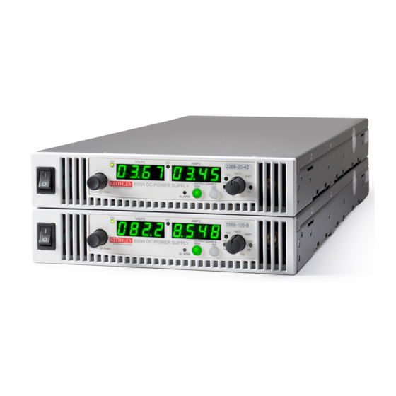
Series 2268 850 Watt DC Power Supplies Reference Manual Introduction SERIES 2268 850-WATT MODELS Output Voltage Output Current Model 2268-20-42 0-20 V 0-42 A 2268-40-21 0-40 V 0-21 A 2268-60-14 0-60 V 0-14 A 2268-80-10.5 0-80 V 0-10.5 A 2268-100-8.5 0-100 V 0-8.5 A 2268-150-5.6... - Page 16 Introduction Series 2268 850 Watt DC Power Supplies Reference Manual Figure 2: Series 2268 850-Watt Front Panel Display and Controls Item Description Rotary Adjust/Enter control Constant Voltage (CV) Mode LED (green) Constant Current (CC) Mode LED (green) Output Current Display Model Identification Label Output Voltage Display Alarm Indicator LED (red)
-
Page 17: Rear Panel Familiarization
Series 2268 850 Watt DC Power Supplies Reference Manual Introduction REAR PANEL FAMILIARIZATION Figure 3: Series 2268 850-Watt, 20 V to 40 V Rear Panel Figure 4: Series 2268 850-Watt, 60 V to 150 V Rear Panel 2268S-901-01 Rev. A / January 2015... - Page 18 Introduction Series 2268 850 Watt DC Power Supplies Reference Manual Item Description 20 V– 40 V Models: DC Output Terminal Positive (6.5 mm hole diameter) 60 V–150 V Models: DC Output Connectors Positive 20 V– 40 V Models: DC Output Terminal Negative (6.5 mm hole diameter) 60 V–150 V Models: DC Output Connectors Negative 3 (J2) Ethernet (ENET) or GPIB Connector...
-
Page 19: Installation
Section 2 Installation In this section: This section provides information and procedures for inspecting, installing, and testing the power supply. BASIC SETUP PROCEDURE Below is a summary of the basic setup procedure with references to the relevant sections in this section. Refer to this table if you are unfamiliar with the installation requirements for the power supply. -
Page 20: Step 1: Inspecting And Cleaning
Installation Series 2268 850 Watt DC Power Supplies Reference Manual STEP 1: INSPECTING AND CLEANING Initial Inspection When you first receive your unit, perform a physical check: Inspect the unit for any scratches and cracks, broken switches, connectors or displays. Ensure that the packing box contains a power cord. -
Page 21: Step 2: Location And Mounting
Series 2268 850 Watt DC Power Supplies Reference Manual Installation STEP 2: LOCATION AND MOUNTING The power supply may be rack-mounted or used in benchtop applications. Rack Mounting Keithley offers a Single and a Dual Rack Kit (2268-RMK-1 and 2268-RMK-2). See "Rack Mount Kit Options"... -
Page 22: Step 3: Connecting Ac Input Power
Installation Series 2268 850 Watt DC Power Supplies Reference Manual STEP 3: CONNECTING AC INPUT POWER WARNING: Shock hazard Disconnect AC power from the unit before removing the cover. Even with the front panel power switch in the Off position, live line voltages are exposed when the cover is removed. -
Page 23: Step 4: Selecting Load Wires
Series 2268 850 Watt DC Power Supplies Reference Manual Installation STEP 4: SELECTING LOAD WIRES This section provides recommendations for selecting minimum load wire sizes. Load Wiring To select the wiring for connecting the load to the power supply, consider the following factors: •... -
Page 24: Maximum Load Wiring Length For Operation With Sense Lines
Installation Series 2268 850 Watt DC Power Supplies Reference Manual Maximum Load Wiring Length For Operation With Sense Lines Figure 5: Maximum Load Wire Length for 1 V Line Drop WIRE GAUGE (AWG) LOAD CURRENT (AMPS) Noise and Impedance Effects To minimize noise pickup or radiation, use shielded twisted pair wiring of the shortest possible length for load sense wires. -
Page 25: Step 5: Performing Functional Tests
Series 2268 850 Watt DC Power Supplies Reference Manual Installation STEP 5: PERFORMING FUNCTIONAL TESTS The functional test procedures include: • Power-on and front panel functional checks • Voltage mode operation and current mode operation checks. For information on local operation, see the section on “Local Operation” on page 30 for adjusting front panel controls and settings. -
Page 26: Voltage And Current Mode Operation Checks
Installation Series 2268 850 Watt DC Power Supplies Reference Manual Voltage and Current Mode Operation Checks To perform the voltage and current mode operation checks: Ensure that the front panel power switch is in the On position and the output is disconnected. -
Page 27: Step 6: Connecting Loads
Series 2268 850 Watt DC Power Supplies Reference Manual Installation STEP 6: CONNECTING LOADS This section describes how to connect loads to the power supply for both single and multiple loads. WARNING: Shock hazard There is a shock hazard at the power supply output when operating at an output greater than 40 V. -
Page 28: Inductive Loads And Batteries
Installation Series 2268 850 Watt DC Power Supplies Reference Manual Inductive Loads and Batteries CAUTION The power supply requires freewheeling and blocking diodes across the output while driving inductive loads or batteries to protect the power supply from damage caused by power being fed back into the supply and from high voltage transients. -
Page 29: Connecting Single Loads
Series 2268 850 Watt DC Power Supplies Reference Manual Installation Connecting Single Loads Figure 7 shows the recommended load connections for a single load which is sensing its voltage locally. Local sense lines shown are the default connections at the rear panel APG J1 connector. -
Page 30: Step 7: Connecting Remote Sensing
Installation Series 2268 850 Watt DC Power Supplies Reference Manual STEP 7: CONNECTING REMOTE SENSING WARNING: Shock hazard There is a potential shock hazard at the sense connectors when using a power supply at an output greater than 40 V. Select wiring with a minimum insulation rating equivalent to the maximum output voltage of the power supply for use as local sense jumpers or for remote sense wires. - Page 31 Series 2268 850 Watt DC Power Supplies Reference Manual Installation Connect one end of the shield of the twisted pair wire to the chassis ground point on the power supply. Connect the positive sense line (+SNS) from the positive regulation point as close as possible to the load terminals to pin J1-1.
-
Page 32: Local Operation
Section 3 Local Operation In this section: This section provides the procedures for local (front panel) operation such as: • Configuring settings. • Operating in constant voltage mode, constant current mode, and constant power mode). • Using the protection features. •... -
Page 33: Coarse And Fine Adjustment Modes
Series 2268 850 Watt DC Power Supplies Reference Manual Local Operation Coarse and Fine Adjustment Modes The coarse and fine adjustment modes are used for setting the voltage and current set points, OVP and UVP settings. Coarse adjustment mode When using local operation to set the current and voltage set points, use the coarse adjustment mode (default) followed by the fine adjustment mode (described next). -
Page 34: Navigating The Menu System
Local Operation Series 2268 850 Watt DC Power Supplies Reference Manual NAVIGATING THE MENU SYSTEM The menu system follows a select and set model with the exception of the VOLTS and AMPS modes. See “Setting VOLTS and AMPS Modes” next. The general procedure for setting up the features in the select and set model is: To select a mode, rotate the 9-position Mode control to the desired mode or press the rotary Adjust/Enter control once to activate the current selection on the mode... -
Page 35: Normal Display Mode And Inactivity Timeout
Series 2268 850 Watt DC Power Supplies Reference Manual Local Operation To access the tracking mode for entering voltage and current: Select the VOLTS or AMPS position on the 9-position mode control. If the set point is blinking, the unit is in coarse tracking mode. •... - Page 36 Local Operation Series 2268 850 Watt DC Power Supplies Reference Manual Figure 10: Front Panel Menu System 2268S-901-01 Rev. A / January 2015...
-
Page 37: Display Messages On The Front Panel
Series 2268 850 Watt DC Power Supplies Reference Manual Local Operation DISPLAY MESSAGES ON THE FRONT PANEL The front panel displays on the power supply will use text as shown in the table that follows to indicate the status or mode. Display Text Text Description Negative Polarity... - Page 38 Local Operation Series 2268 850 Watt DC Power Supplies Reference Manual Display Text Text Description Interlock ENET Interface Current APG Level Voltage APG Level Lock Local Loop Protection Output Protection Over Current Protection Over Temperature Protection Over Voltage Protection Over Voltage Protection fine adjustment OVP Calibration Polarity Protection mode...
-
Page 39: Standard (Local) Operation
Series 2268 850 Watt DC Power Supplies Reference Manual Local Operation STANDARD (LOCAL) OPERATION The power supply can be controlled by two methods, either from the front panel or from any of the remote interfaces. Front panel control is referred to as local operation (default setting) while control via any of the remote interfaces is called remote operation. -
Page 40: Constant Current (Cc) Mode Operation
Local Operation Series 2268 850 Watt DC Power Supplies Reference Manual Constant Current (CC) Mode Operation If the output is enabled, the voltage and current start to rise. At this time the unit is operating in CV mode (default operational mode). As the load current drawn reaches the value of the output current setting, the unit will switch to CC mode and not allow any additional current to be drawn above the value of I . - Page 41 Series 2268 850 Watt DC Power Supplies Reference Manual Local Operation The reverse operating mode change can also occur if the load resistance is increased to the point that the required load current drops below the I value. At that point the power supply would crossover to CV mode and the load current would be free to vary as the load resistance changed.
- Page 42 Local Operation Series 2268 850 Watt DC Power Supplies Reference Manual Important: The maximum and minimum setting values of the output voltage are limited by the Over Voltage Protection and Under Voltage Protection settings. To set the current set point (I Turn the 9-position mode control to the AMPS position or press the rotary Adjust/Enter control if the 9-position mode control is already at the AMPS position.
-
Page 43: Shipped Configuration (Local Operation)
Series 2268 850 Watt DC Power Supplies Reference Manual Local Operation SHIPPED CONFIGURATION (LOCAL OPERATION) The power supply is configured for local operation at the factory. See the table that follows for a summary of this configuration. Local Control Configuration Additional References Use the front panel controls to See section on “Local Operation”... -
Page 44: Enabling The Auxiliary Output
Local Operation Series 2268 850 Watt DC Power Supplies Reference Manual ENABLING THE AUXILIARY OUTPUT To enable on the auxiliary output: ♦ Press the OUTPUT ENABLE Aux button on the front panel. The OUTPUT ENABLE Aux button will illuminate. Important: The auxiliary output will not be enabled if the external AUX_ON_OFF signal line is being used to disable the auxiliary outputs. -
Page 45: Auxiliary Auto Start Mode
Series 2268 850 Watt DC Power Supplies Reference Manual Local Operation AUXILIARY AUTO START MODE The Auxiliary Auto Start mode determines the state of the auxiliary output after a complete power cycle (all front panel LEDS are not illuminated). With Auxiliary Auto Start mode turned to On, the auxiliary output will be activated after the power supply is powered up again. -
Page 46: Alarms And Errors
Local Operation Series 2268 850 Watt DC Power Supplies Reference Manual Turn the rotary Adjust/Enter control until “NONE” is displayed in the output current display. Press the rotary Adjust/Enter control to commit the setting once the desired value has been set. The green FLD LED will turn off and the display will return to the normal display mode. -
Page 47: Clearing Alarms
Series 2268 850 Watt DC Power Supplies Reference Manual Local Operation CLEARING ALARMS Clearing Triggered and Manual Alarms To clear a triggered alarm, use one of the following methods: • Turn the power supply Off and then On. • Press and hold the rotary Adjust/Enter control for 3 seconds. To clear a manual alarm: Press and hold the rotary Adjust/Enter control for 3 seconds. -
Page 48: Clearing Automatic Alarms
Local Operation Series 2268 850 Watt DC Power Supplies Reference Manual Clearing Automatic Alarms Some alarms will clear automatically when the condition that caused the alarm is no longer present. When an alarm automatically clears, the output voltage and current displays will return to normal, but the ALARM LED will remain illuminated to indicate that an alarm has occurred. -
Page 49: Alarm Masking
Series 2268 850 Watt DC Power Supplies Reference Manual Local Operation The alarm LED will remain illuminated until the alarm is manually cleared (see “Clearing Triggered and Manual Alarms” on page 45) or by turning the main output on if the alarm has automatically been cleared. -
Page 50: Alarm Output Latching
Local Operation Series 2268 850 Watt DC Power Supplies Reference Manual Alarm Output Latching When an alarm is triggered, the output will be disabled with the exception of the Fan alarm. When an alarm is cleared, the alarm output latch determines if the output should be re-enabled to the state before the alarm occurred or if the output should remain in the off state. -
Page 51: Setting Foldback Mode
Series 2268 850 Watt DC Power Supplies Reference Manual Local Operation SETTING FOLDBACK MODE Foldback mode is used to disable the output when a transition is made between the operating modes. The power supply will turn off/disable the output and lock in foldback mode after a specified delay if the power supply transitions into CV mode or into CC mode, depending on the foldback mode settings. -
Page 52: Resetting Activated Foldback Protection
Local Operation Series 2268 850 Watt DC Power Supplies Reference Manual RESETTING ACTIVATED FOLDBACK PROTECTION To reset activated and latched foldback protection, press and hold the rotary Adjust/Enter control for approximately 3 seconds. The SCPI command (s) for these instructions are: [:]OUTPut[<channel>]:PROTection:CLEar USING OVER VOLTAGE PROTECTION (OVP) The OVP circuit protects the load in the event of an analog programming error, an incorrect... -
Page 53: Using Under Voltage Protection (Uvp)
Series 2268 850 Watt DC Power Supplies Reference Manual Local Operation USING UNDER VOLTAGE PROTECTION (UVP) Important: UVP will not be active for voltage set points that are less than 1% of model voltage. The UVP prevents voltage settings below a set value. The UVP lets you create a voltage window of operation when used in conjunction with the OVP setting. -
Page 54: Using Over Temperature Protection Lock (Otp)
Local Operation Series 2268 850 Watt DC Power Supplies Reference Manual USING OVER TEMPERATURE PROTECTION LOCK (OTP) The OTP lock protects the power supply in the event of an over temperature alarm. This alarm could be caused by ventilation restriction or overheating due to fan failure. Two modes are available: Auto recovery (OTP OFF) where the power supply turns on again after cooling down. -
Page 55: Using The External Shutdown Function
Series 2268 850 Watt DC Power Supplies Reference Manual Local Operation USING THE EXTERNAL SHUTDOWN FUNCTION Use the external shutdown function to enable or disable the output of the power supply via a logic level signal. When the external shutdown is triggered, the power supply will display SD POL on the output voltage and current displays. -
Page 56: Defining The Polarity Of The External Shutdown Signal
Local Operation Series 2268 850 Watt DC Power Supplies Reference Manual Defining the Polarity of the External Shutdown Signal Turn the 9-position mode control to the PRT position or press the rotary Adjust/Enter control if the control knob is already at the PRT position. is displayed on the output voltage display. - Page 57 Series 2268 850 Watt DC Power Supplies Reference Manual Local Operation Figure 13: Loop Protection Setup To enable or disable Loop Protection: Turn the 9-position mode control to the PRT position. PRO OVP is displayed. Turn the rotary Adjust/Enter control until LOOP PRO is displayed. Press the rotary Adjust control to display LOOP ON or OFF.
-
Page 58: Interlock Function
Local Operation Series 2268 850 Watt DC Power Supplies Reference Manual INTERLOCK FUNCTION The Interlock function can be used to wire an external shutoff switch that can be used to enable or disable the power supply output. When the switch is closed, the power supply will operate normally. -
Page 59: Programming Current Output Preset
Series 2268 850 Watt DC Power Supplies Reference Manual Local Operation Programming Current Output Preset To Enable/Disable automatic reset to 0 Amps: Turn the rotary Adjust/Enter control to PRT and press. Turn again until is displayed. Press to display Turn to display Press to commit the selected setting. -
Page 60: Hardware Malfunction Alarms
Local Operation Series 2268 850 Watt DC Power Supplies Reference Manual HARDWARE MALFUNCTION ALARMS The power supply will turn off the output. An error message will be displayed in the event that: • OVP trips • Voltage deviation in CV mode reaches more than ±5% from the set level. •... -
Page 61: User Setting Memory Locations
Series 2268 850 Watt DC Power Supplies Reference Manual Local Operation USER SETTING MEMORY LOCATIONS There are three user setting memory locations available for storing frequently used configurations. These user setting memory locations help to facilitate multiple users of a Series 2268 power supply who have different setups or when multiple loads are used that have different requirements. -
Page 62: Recalling User Setting Memory Locations
Local Operation Series 2268 850 Watt DC Power Supplies Reference Manual Recalling User Setting Memory Locations This feature recalls settings that were previously saved. To load user setting memory locations: Turn the 9-position mode control to the RCL position. is displayed on the output voltage display with a number indicating a preset position on the output current display. -
Page 63: Local Lockout
Series 2268 850 Watt DC Power Supplies Reference Manual Local Operation LOCAL LOCKOUT Local lockout is a feature that allows the front panel to be locked so that accidental button presses are ignored. This feature is often used to lockout the front panel when you are controlling the power supply from a remote location. -
Page 64: Resetting The Power Supply
Local Operation Series 2268 850 Watt DC Power Supplies Reference Manual RESETTING THE POWER SUPPLY The reset is used to clear the parameters to the factory default values. Soft Reset The soft reset is used to set the parameters (see table below) to the default values, but it does not reset the calibration constants To perform a soft reset: Turn the power supply to Off then On. -
Page 65: Using Multiple Power Supplies
Series 2268 850 Watt DC Power Supplies Reference Manual Local Operation Parameter Setting Voltage APG Scale 10 V Current Analog Programming Current APG Scale 10 V Voltage Output Protection Current Output Protection USING MULTIPLE POWER SUPPLIES WARNING: Shock hazard There is a shock hazard at the load when using a power supply at an output of greater than 40V or a combined output of greater than 40V. -
Page 66: Configuring Multiple Supplies For Series Operation
Local Operation Series 2268 850 Watt DC Power Supplies Reference Manual Figure 14: Bipolar Supply Operation CONFIGURING MULTIPLE SUPPLIES FOR SERIES OPERATION A maximum of two power supplies of the same rating can be connected in series to increase the output voltage. CAUTION: Equipment damage When two power supplies are connected in series, they should be programmed to the same output voltage to prevent damage to the lower voltage supply at... -
Page 67: Connecting To The Load In Local Sensing Mode
Series 2268 850 Watt DC Power Supplies Reference Manual Local Operation BLOCKING and FREE WHEELING DIODES: The Peak Reverse Voltage ratings should be a minimum of 2-3 times the power supply maximum output voltage. The Continuous Forward Current rating should be a minimum of 1.5 times the power supply maximum output current. -
Page 68: Connecting To The Load In Remote Sensing Mode
Local Operation Series 2268 850 Watt DC Power Supplies Reference Manual Connecting to the Load in Remote Sensing Mode Connect the negative (-) output terminal of one power supply to the positive (+) output terminal of the next power supply. The more positive supply's positive sense line should connect to the positive terminal of the load (or distribution point). -
Page 69: Configuring Multiple Supplies For Current Sharing Operation
Series 2268 850 Watt DC Power Supplies Reference Manual Local Operation CONFIGURING MULTIPLE SUPPLIES FOR CURRENT SHARING OPERATION (APG METHOD) Up to four power supplies can be connected in parallel to increase the output current. One of the units will operate as the master unit and the remaining units will operate as slave units controlled by the master unit. -
Page 70: Setting Up The Slave Units
Local Operation Series 2268 850 Watt DC Power Supplies Reference Manual Press the rotary Adjust/Enter control to commit the setting. The SCPI command (s) for these instructions are: [[:]SOURce[<channel>]]:COMBine:CSHare[:MODE] Setting up the Slave Units The output voltage and current of the slave units should be programmed to maximum value. During parallel operation, the slave units operate as a controlled current source following the controller unit's output current. -
Page 71: Setting Foldback Protection
Series 2268 850 Watt DC Power Supplies Reference Manual Local Operation Setting Foldback Protection Foldback protection is only available on the master units as the slaves operate in constant current mode. They should never crossover into constant voltage mode. If foldback is triggered on the master unit, when its output shuts down, it will program the slave unit's output to zero volts. -
Page 72: Connecting To The Load In Remote Sensing Mode (Parallel Control Method)
Local Operation Series 2268 850 Watt DC Power Supplies Reference Manual CONNECTING TO THE LOAD IN REMOTE SENSING MODE (PARALLEL CONTROL METHOD) Figure 18: Load Connections in Remote Sensing Mode (Parallel Control Method) MASTER PSU Shielded Twisted Pair LOAD To other slaves SLAVE PSU POWER SAVING CONTROL (SLEEP MODE) The Sleep Mode, supported by Series 2268 power supplies, is an effective way to reduce... - Page 73 Series 2268 850 Watt DC Power Supplies Reference Manual Local Operation To enable Sleep Mode: Set a time delay for the duration of inactivity to elapse before entering Sleep Mode. This time (sleep hold-off delay) can be set from the Protection menu, under the SLP entry. The sleep hold off delay can be set from 1 to 9 hours.
-
Page 74: Analog Programming & Isolated Analog Programming
Section 4 Analog Programming & Isolated Analog Programming In this section: This section provides information and procedures for analog and isolated analog programming of the power supply. INTRODUCTION The rear panel connectors J1 and J3 provide an option to control and monitor the output of the power supply with analog signals. -
Page 75: Remote Programming Options
Series 2268 850 Watt DC Power Supplies Reference Manual Analog Programming & Isolated Analog Programming REMOTE PROGRAMMING OPTIONS Analog Monitor Signals There are four monitor lines for analog programming the pin name and the related APG mode, which are listed in the table that follows. All of these lines are provided to give analog feedback. -
Page 76: Analog Programming (Apg) Connector J1
Analog Programming & Isolated Analog Programming Series 2268 850 Watt DC Power Supplies Reference Manual Analog Programming (APG) Connector J1 The APG connector is an 18-pin connector. See Figure 19. The APG connector provides access to the following functions: • Sense control •... -
Page 77: Making Control Connections
Series 2268 850 Watt DC Power Supplies Reference Manual Analog Programming & Isolated Analog Programming Reference Function J1.15 EXT_CC_CV External CC/CV. Indicates the state of the operate mode. When in CV mode, logic high is output and when in CC mode, logic low is output. -
Page 78: Wiring
Analog Programming & Isolated Analog Programming Series 2268 850 Watt DC Power Supplies Reference Manual Wiring WARNING: Shock hazard There is a potential shock hazard at the output when using a power supply with a rated output greater than 60 V. Use load wires that match the maximum voltage, current, and temperature ranges that you expect in your application. -
Page 79: Voltage-Controlled Voltage Apg Setup
Series 2268 850 Watt DC Power Supplies Reference Manual Analog Programming & Isolated Analog Programming Voltage-Controlled Voltage APG Setup Activating APG Voltage Mode To activate APG voltage mode using an external voltage source: Turn the 9-position mode control to the VAP position or press the rotary Adjust/Enter control if the mode control is already at the VAP position. - Page 80 Analog Programming & Isolated Analog Programming Series 2268 850 Watt DC Power Supplies Reference Manual Query for Analog Voltage Input Level To query for analog voltage input level from non-isolated input: Turn the 9-position mode control to the VAP position or press the rotary Adjust/Enter control if the mode control is already at the VAP position.
-
Page 81: Voltage-Controlled Current Apg Setup
Series 2268 850 Watt DC Power Supplies Reference Manual Analog Programming & Isolated Analog Programming Voltage-Controlled Current APG Setup Activating APG Current Mode To activate APG current mode using an external voltage source: Turn the 9-position mode control to the CAP position or press the rotary Adjust/Enter control if the mode control is already at the CAP position. - Page 82 Analog Programming & Isolated Analog Programming Series 2268 850 Watt DC Power Supplies Reference Manual Query for Analog Current Input Level To query for analog current input level from non-isolated input: Turn the 9-position mode control to the CAP position or press the rotary Adjust/Enter control if the mode control is already at the CAP position.
-
Page 83: Analog Programming With External Resistor
Series 2268 850 Watt DC Power Supplies Reference Manual Analog Programming & Isolated Analog Programming ANALOG PROGRAMMING WITH EXTERNAL RESISTOR Figure 24: Programming Output Voltage using an External Resistor Figure 25: Programming Output Current using an External Resistor APG Connector 2268S-901-01 Rev. -
Page 84: Resistive-Controlled Voltage Apg Setup
Analog Programming & Isolated Analog Programming Series 2268 850 Watt DC Power Supplies Reference Manual Resistive-Controlled Voltage APG Setup Activating APG Voltage Mode To activate APG voltage mode using an external resistor: Turn the 9-position mode control to the VAP position or press the rotary Adjust/Enter control if the mode control is already at the VAP position. - Page 85 Series 2268 850 Watt DC Power Supplies Reference Manual Analog Programming & Isolated Analog Programming Query for Analog Voltage Input Level To query for analog voltage input level from non-isolated input: Turn the 9-position mode control to the VAP position or press the rotary Adjust/Enter control if the mode control is already at the VAP position.
-
Page 86: Resistive-Controlled Current Apg Setup
Analog Programming & Isolated Analog Programming Series 2268 850 Watt DC Power Supplies Reference Manual Resistive-Controlled Current APG Setup Activating APG Current Mode To activate APG current mode using an external resistor source: Turn the 9-position mode control to the CAP position to press the rotary Adjust/Enter control if the control knob is already at CAP position. - Page 87 Series 2268 850 Watt DC Power Supplies Reference Manual Analog Programming & Isolated Analog Programming Query for Analog Current Input Level To query for analog current input level from non-isolated input: Turn the 9-position mode control to the CAP position or press the rotary Adjust/Enter control if the mode control is already at the CAP position.
-
Page 88: Voltage And Current Readback
Analog Programming & Isolated Analog Programming Series 2268 850 Watt DC Power Supplies Reference Manual VOLTAGE AND CURRENT READBACK Figure 26: Voltage Readback using APG Connector J1 Figure 27: Current Readback using APG Connector J1 2268S-901-01 Rev. A / January 2015... -
Page 89: Isolated Analog Programming Mode (Isol)
Series 2268 850 Watt DC Power Supplies Reference Manual Analog Programming & Isolated Analog Programming ISOLATED ANALOG PROGRAMMING MODE (ISOL) See “Rear Panel Familiarization” on page 15 for more details about connections. AUX Output and Isolated Analog Programming (ISOL) Connector The AUX Output and Isolated Analog Programming (ISOL) Connector is a 15-pin female DSUB connector. - Page 90 Analog Programming & Isolated Analog Programming Series 2268 850 Watt DC Power Supplies Reference Manual Reference Function J3.1 AUX_ON_OFF Auxiliary enable/disable J3.2 COM_ISOLATED Isolated Common (Isolated from Main Output and Communication. Return wire for +5 V, +15 V Auxiliary Voltage. J3.3 IS_VOL_PR_VOL Isolated Analog Voltage Programming Input...
-
Page 91: Making Isol Control Connections
Series 2268 850 Watt DC Power Supplies Reference Manual Analog Programming & Isolated Analog Programming Making ISOL Control Connections CAUTION: Equipment damage Before making connections from external circuits to the Isolated Analog Programming Connector, turn the front panel power switch to off and wait until the front panel displays have gone out. -
Page 92: Voltage-Controlled Voltage Isol Setup
Analog Programming & Isolated Analog Programming Series 2268 850 Watt DC Power Supplies Reference Manual Voltage-Controlled Voltage ISOL Setup Activating ISOL Programming Voltage Mode To activate ISOL programming voltage mode with an external voltage source: Turn the 9-position mode control to the VAP position or press the rotary Adjust/Enter control if the mode control is already at the VAP position. - Page 93 Series 2268 850 Watt DC Power Supplies Reference Manual Analog Programming & Isolated Analog Programming Query for ISOL Voltage Input Level To query for ISOL voltage input level from non-isolated input: Turn the 9-position mode control to the VAP position or press the rotary Adjust/Enter control if the control knob is already at the VAP position.
-
Page 94: Voltage-Controlled Current Isol Setup
Analog Programming & Isolated Analog Programming Series 2268 850 Watt DC Power Supplies Reference Manual Voltage-Controlled Current ISOL Setup Activating ISOL Programming Current Mode Turn the 9-position mode control to the CAP position or press the rotary adjust/Enter control if the control knob is already at the CAP position. is displayed on the output voltage display. - Page 95 Series 2268 850 Watt DC Power Supplies Reference Manual Analog Programming & Isolated Analog Programming Query for ISOL Current Input Level To query for ISOL current input level from non-isolated input: Turn the 9-position mode control to the CAP position or press the rotary Adjust/Enter control if the control knob is already at the CAP position.
-
Page 96: Analog Programming With External Resistor
Analog Programming & Isolated Analog Programming Series 2268 850 Watt DC Power Supplies Reference Manual ANALOG PROGRAMMING WITH EXTERNAL RESISTOR Figure 31: Programming Output Voltage using an Isolated External Resistor ISOL Connector Figure 32: Programming Output Current using an Isolated External Resistor ISOL Connector 2268S-901-01 Rev. -
Page 97: Resistive-Controlled Voltage Isol Setup
Series 2268 850 Watt DC Power Supplies Reference Manual Analog Programming & Isolated Analog Programming Resistive-Controlled Voltage ISOL Setup Activating ISOL Programming Voltage Mode To activate ISOL programming voltage mode using an external resistor: Turn the 9-position mode control to the VAP position or press the rotary adjust/Enter control if the control knob is already at the VAP position. - Page 98 Analog Programming & Isolated Analog Programming Series 2268 850 Watt DC Power Supplies Reference Manual Query for ISOL Voltage Input Level To query for ISOL voltage input level from non-isolated input: Turn the 9-position mode control to the VAP position or press the rotary Adjust/Enter control if the control knob is already at the VAP position.
-
Page 99: Resistive-Controlled Current Isol Setup
Series 2268 850 Watt DC Power Supplies Reference Manual Analog Programming & Isolated Analog Programming Resistive-Controlled Current ISOL Setup Activating ISOL Resistive-Controlled Current Setup Turn the 9-position mode control to the CAP position or press the rotary Adjust/Enter control if the control knob is already at the CAP position. is displayed on the output voltage display. - Page 100 Analog Programming & Isolated Analog Programming Series 2268 850 Watt DC Power Supplies Reference Manual Query for ISOL Current Input Level To query for ISOL current input level from non-isolated input: Turn the 9-position mode control to the CAP position or press the rotary Adjust/Enter control if the control knob is already at the CAP position.
-
Page 101: Voltage And Current Readback (Isolated)
Series 2268 850 Watt DC Power Supplies Reference Manual Analog Programming & Isolated Analog Programming VOLTAGE AND CURRENT READBACK (ISOLATED) Figure 33: Isolated Voltage Monitoring ISOL Connector Figure 34: Isolated Current Monitoring ISOL Connector QUERY REMOTE CONTROL SOURCE STATE The SCPI command for these instructions are: Quick Tip: Remote operation uses these SCPI commands. -
Page 103: Remote Operation
Section 5 Remote Operation In this section: This section describes the remote operation of the power supply via the communication ports. INTRODUCTION In addition to the front panel interface, the power supply can be remotely controlled through the various remote interfaces. The power supply implements the SCPI standard as its command line interface for remotely controlling the power supply. -
Page 104: Configuring Remote Control Using Rs-232
Remote Operation Series 2268 850 Watt DC Power Supplies Reference Manual CONFIGURING REMOTE CONTROL USING RS-232 To configure remote control using RS-232: Use the top J4 connector of the two 8-pin RJ-45 jacks, as shown in Figure 35, to connect to the RS-232 remote interface. Connect from PC to power supply using a cable that meets the cabling specifications listed in the table that follows. -
Page 105: Communication Cable With Rj-45 To Db-9
Series 2268 850 Watt DC Power Supplies Reference Manual Remote Operation RS-232 Communication Cable with RJ-45 to DB-9 Communication control cable with DB-9 connector (male) on the PC side and RJ-45 shielded connector on the power supply. The suggested cable length should be 9.84 feet (3 m). DB-9 Pinouts Name Description... -
Page 106: Communication Cable With Rj-45 To Db-25
Remote Operation Series 2268 850 Watt DC Power Supplies Reference Manual Figure 36: RS-232 Communication Cable with DB-9 Pinout DB-9 Pinout DB-9 connector on PC RJ-45 plug RS-232 Communication Cable with RJ-45 to DB-25 Communication control cable with DB-25 pinout (male) on the PC side and RJ-45 shielded connector on the power supply. - Page 107 Series 2268 850 Watt DC Power Supplies Reference Manual Remote Operation Figure 38: RS-232 Communication Cable with DB-25 Pinout Completing the Setup To complete the setup: Configure the power supply to use the 232 remote interface and set up the terminal that will be used on the connected PC.
-
Page 108: Configuring Remote Control Using Rs-485
Remote Operation Series 2268 850 Watt DC Power Supplies Reference Manual CONFIGURING REMOTE CONTROL USING RS-485 RS-485 Communication Cable with RJ-45 to DB-9 Communication control cable with DB-9 pinout (female) on the PC side (see Figure 36) and RJ-45 shielded connector on the power supply. CAUTION: Equipment damage Figure 39 shows an example of wiring for NI RS485 communication cable with DB-9. -
Page 109: Rs-485 Communication Cable With Two Rj-45S
Series 2268 850 Watt DC Power Supplies Reference Manual Remote Operation RS-485 Communication Cable with Two RJ-45s Use the top connector of the two 8-pin RJ-45 jacks, as shown in Figure 40, to connect to the RS-485 remote interface. Communication cable with two RJ-45 shielded connectors connecting the master unit to the slave unit. -
Page 110: Configuring Remote Control Using Usb
Remote Operation Series 2268 850 Watt DC Power Supplies Reference Manual CONFIGURING REMOTE CONTROL USING USB The power supply can be controlled from a remote terminal using a USB interface. The standard USB connector is located on the rear panel. Use a standard USB shielded cable up to 9.84 feet (3 m) in length. - Page 111 Series 2268 850 Watt DC Power Supplies Reference Manual Remote Operation Launch the Device Driver Installation by clicking Next. See Figure 42. Figure 42: Device Driver Installation Wizard 2268S-901-01 Rev. A / January 2015...
- Page 112 Remote Operation Series 2268 850 Watt DC Power Supplies Reference Manual Click the radio button to indicate acceptance of agreement, (click Save As and or Print button(s) to maintain a copy of the agreement, if desired), and click Next to begin the installation.
- Page 113 Series 2268 850 Watt DC Power Supplies Reference Manual Remote Operation To complete the installation, click Finish. See Figure 44. Figure 44: Completing the Device Driver Installation Wizard 10. Once the installation is complete, connect your device to a spare USB port on your computer.
- Page 114 Remote Operation Series 2268 850 Watt DC Power Supplies Reference Manual To verify that the device has been installed: In Control Panel, go to System, click the Hardware tab and click on Device Manager. The Device Manager window displays. See Figure 45. Figure 45: Device Manager On the View menu, select Devices by Type.
- Page 115 Series 2268 850 Watt DC Power Supplies Reference Manual Remote Operation Click the Port Settings tab, then click Advanced. See Figure 46. Figure 46: Communications Port (COM5) Properties In the COM port list, scroll to the required COM port. Figure 47: Advanced Settings for (COM5) Port 2268S-901-01 Rev.
-
Page 116: Configuring Remote Conrol Using Gpib
Remote Operation Series 2268 850 Watt DC Power Supplies Reference Manual Click OK. Ensure that you do not select a COM port which is already in use. This selection is particularly useful for programs, such as HyperTerminal, which only work with COM1 through to COM4. -
Page 117: Communication With Your Device
Series 2268 850 Watt DC Power Supplies Reference Manual Remote Operation SRQ Return Chassis ATN Return Chassis Signal Ground Chassis Communication with Your Device This section provides information on selecting the GPIB interface as the communication port used on the power supply, and it also provides an example of how commands can be sent and received. - Page 118 Remote Operation Series 2268 850 Watt DC Power Supplies Reference Manual Figure 48: Scanning for Instruments In the “Connected Instruments” panel of the GPIB explorer window, click on Instrument 0 and review the device properties. See Figure 49. 2268S-901-01 Rev. A / January 2015...
-
Page 119: Configuring Remote Control Using Ethernet/Lan (Enet)
Series 2268 850 Watt DC Power Supplies Reference Manual Remote Operation Figure 49: Instrument Properties Click Communicate with Instrument in the GPIB Explorer toolbar. (See Figure 49). NI-488.2 Communicator appears. In the Send String box of the NI-488.2 Communicator window, type *IDN? and click the Query button. -
Page 120: Multiple Power Supply Connections To Rs-485 Bus
Remote Operation Series 2268 850 Watt DC Power Supplies Reference Manual MULTIPLE POWER SUPPLY CONNECTIONS TO RS-485 BUS Up to 30 units may be connected to the RS-485 bus. The first unit (master unit) connects to the controller via any appropriate port, and the other units (slave units) are connected with the RS-485 bus via the J6 connector. -
Page 121: Terminal Configuration
Series 2268 850 Watt DC Power Supplies Reference Manual Remote Operation TERMINAL CONFIGURATION The terminal program allows serial communication with the power supply. To use a terminal program, set it up using the parameters from the following sections. If you wish to use HyperTerminal, see “HyperTerminal”... - Page 122 Remote Operation Series 2268 850 Watt DC Power Supplies Reference Manual This is the COM port that you have your serial cable hooked up to or in the case of USB the one that was configured to be used in the FDTI software. Click OK when done.
- Page 123 Series 2268 850 Watt DC Power Supplies Reference Manual Remote Operation Figure 52: ASCII Setup 11. Check the following boxes: Send line ends with line feeds. Echo typed characters locally. Append line feeds to incoming line ends. Wrap lines that exceed terminal width. 12.
-
Page 124: Selecting The Appropriate Communication Port
Remote Operation Series 2268 850 Watt DC Power Supplies Reference Manual SELECTING THE APPROPRIATE COMMUNICATION PORT Five ports are available for remote digital programming and readback: • RS-232 • RS-485 • • GPIB • ENET To select a communication port: Turn the 9-position mode control to PGM. -
Page 125: Multichannel Address Setting
Series 2268 850 Watt DC Power Supplies Reference Manual Remote Operation Multichannel Address Setting Important: Always start communication with the Series 2268 by sending the *ADR <address> command to select the unit you want to talk to. If you do not do this, the instrument may not respond to commands. -
Page 126: Multichannel Commands Explained
Remote Operation Series 2268 850 Watt DC Power Supplies Reference Manual Multichannel Commands Explained The use of multichannel addressing allows you to send messages to one device, more than one device or to all devices. Any of the remote interface types can be used to send a multichannel command through the device that is physically connected to the PC to all the devices, provided that all other devices are connected to via the RS-485 bus. -
Page 127: Status Reporting In Scpi
Series 2268 850 Watt DC Power Supplies Reference Manual Remote Operation Multichannel commands are particularly useful for configuring groups of devices that require identical configurations. The SCPI Commands for these instructions are: [:]<root command> <ALL|addr1>[,[ ]<addr2>][,[ ]<addr3>][,...]:<command> <parameter> For example: sour1, 2, 3, 7:volt 4.5 syst4,5,6:oper:enab 255 sourALL:volt 5... - Page 128 Remote Operation Series 2268 850 Watt DC Power Supplies Reference Manual Figure 53: SCPI Status Reporting Model 2268S-901-01 Rev. A / January 2015...
-
Page 129: Status Registers Model From Ieee 488.2
Series 2268 850 Watt DC Power Supplies Reference Manual Remote Operation STATUS REGISTERS MODEL FROM IEEE 488.2 The IEEE 488.2 registers shown in the bottom rectangle of Figure 53 follow the IEEE 488.2 model for status registers. The IEEE 488.2 register only has enable registers for masking the summary bits. -
Page 130: Status Byte
Remote Operation Series 2268 850 Watt DC Power Supplies Reference Manual Status Byte The Status byte register contains the STB and RQS (MSS) messages as defined in 488.1. You can read the status byte register using a 488.1 serial poll or the 488.2 *STB? common command. -
Page 131: Message Available (Mav)
Series 2268 850 Watt DC Power Supplies Reference Manual Remote Operation Message Available (MAV) This bit is TRUE whenever the power supply is ready to accept a request by the Digital Programming Interface to output data bytes. This message is FALSE when the output queue is empty. -
Page 132: Operation Status Register Summary (Osr)
Remote Operation Series 2268 850 Watt DC Power Supplies Reference Manual Operation Status Register Summary (OSR) This bit is TRUE when a bit in the Operation Event Status Register is set and its corresponding bit in the Operation Status Enable Register is set. Service Request Enable Register The Service Request Enable Register allows you to select the reasons for the power supply to issue a service request. -
Page 133: Standard Event Status Register (Sesr)
Series 2268 850 Watt DC Power Supplies Reference Manual Remote Operation Standard Event Status Register (SESR) The standard event status register sets bits for specific events during power supply operation. All bits in the standard event status registers are set through the error event queue. The register is defined by IEEE 488.2 register and is controlled using 488.2 common commands: *ESE, *ESE?, and *ESR? as well as SCPI aliases for multichannel use. - Page 134 Remote Operation Series 2268 850 Watt DC Power Supplies Reference Manual Figure 55 summarizes the Standard Event Status Register. Figure 55: Summary of Standard Event Status Register Standard Event Status Register Bit Weight Bit Name Description Operation Complete Set if * OPC command has been received and all pending (OPC) operations have been completed.
- Page 135 Series 2268 850 Watt DC Power Supplies Reference Manual Remote Operation Operation Complete The Operation Complete command causes the power supply to generate the operation complete message in the Standard Event Status Register when all pending operations have been finished. See bit 0 in the Standard Events Register table above for more details. Command: *OPC, *OPC?
-
Page 136: Standard Scpi Register Structure
Remote Operation Series 2268 850 Watt DC Power Supplies Reference Manual STANDARD SCPI REGISTER STRUCTURE All registers except the SERS and Status registers will have the following structure which control how they report status information. In all subsequent figures that have SCPI registers, this structure will be condensed down into a single block to simplify the figures. -
Page 137: Operation Status Register
Series 2268 850 Watt DC Power Supplies Reference Manual Remote Operation OPERATION STATUS REGISTER The operation status register is a standard SCPI, 16-bit register which contains information about conditions which are part of the power supply's normal operation. The Operation Status data structure has the operation status register and two sub-registers to represent shutdown and protection shutdown. - Page 138 Remote Operation Series 2268 850 Watt DC Power Supplies Reference Manual OPERation Status Register Bit Weight Bit Name Description CALibrating Indicates that the supply is in CALibration Mode. SETTling Not implemented RANGing Not implemented SWEeping Not implemented MEASuring Not implemented Waiting for Arm Not implemented Waiting for Trigger...
-
Page 139: Current Share Sub-Register
Series 2268 850 Watt DC Power Supplies Reference Manual Remote Operation OPERation SHUTdown PROTection Status Register Bit Weight Bit Name Description Over Voltage protection has tripped. Under Voltage protection has tripped. Over Current protection has tripped. Not Used Not Used AC Off AC failure protection has tripped. -
Page 140: Operation Status Register Commands
Remote Operation Series 2268 850 Watt DC Power Supplies Reference Manual Operation Status Register Commands The response format for all register queries will be in decimal notation. Query Operation Status Register Event SCPI command: [:]STATus[<channel>]:OPERation[:EVENt]? Query Operation Status Register Condition SCPI command: [:]STATus[<channel>]:OPERation:CONDition? Enable Operation Status Register... -
Page 141: Current Sharing Sub-Register Commands
Series 2268 850 Watt DC Power Supplies Reference Manual Remote Operation Current Sharing Sub-Register Commands Query Current Share Event SCPI command: [:]STATus[<channel>]:OPERation:CSHare[:EVENt]? Query Current Share Condition SCPI command: [:]STATus[<channel>]:OPERation:CSHare:CONDition? Enable Current Share Sub-Register SCPI command: [:]STATus[<channel>]:OPERation:CSHare:ENABle <statusenable> Query format: [:]STATus[<channel>]:OPERation:CSHare:ENABle? Set Current Share Positive Transition Filter SCPI command: [:]STATus[<channel>]:OPERation:CSHare:PTRansition <status-enable>... -
Page 142: Shutdown Sub-Register Commands
Remote Operation Series 2268 850 Watt DC Power Supplies Reference Manual Shutdown Sub-Register Commands Query Shutdown Event SCPI command: [:]STATus[<channel>]:OPERation:SHUTdown[:EVENt]? Query Shutdown Condition SCPI command: [:]STATus[<channel>]:OPERation:SHUTdown:CONDition? Enable Shutdown Sub-Register SCPI command: [:]STATus[<channel>]:OPERation: SHUTdown:ENABle <status-enable> Query format: [:]STATus[<channel>]:OPERation:SHUTdown:ENABle? Set Shutdown Positive Transition Filter SCPI command: [:]STATus[<channel>]:OPERation:SHUTdown:PTRansition <status-enable>... -
Page 143: Protection Sub-Register Commands
Series 2268 850 Watt DC Power Supplies Reference Manual Remote Operation Protection Sub-Register Commands Query Protection Event SCPI command: [:]STATus[<channel>]:OPERation:SHUTdown:PROTection[:EVENt]? Query Protection Condition SCPI command: [:]STATus[<channel>]:OPERation:SHUTdown:PROTection:CONDition? Enable Protection Sub-Register SCPI command: [:]STATus[<channel>]:OPERation: SHUTdown:PROTection:ENABle <status-enable> Query format: [:]STATus[<channel>]:OPERation:SHUTdown:PROTection:ENABle? Set Protection Positive Transition Filter SCPI command: [:]STATus[<channel>]:OPERation:SHUTdown:PROTection:PTRansition <stats-enable>... -
Page 144: Questionable Status Register
Remote Operation Series 2268 850 Watt DC Power Supplies Reference Manual QUESTIONABLE STATUS REGISTER The Questionable Status register is a standard SCPI, 16-bit register that stores information about questionable events or status during power supply operation. That is, bits in these registers may indicate that the output of the supply is of undesirable or questionable quality. - Page 145 Series 2268 850 Watt DC Power Supplies Reference Manual Remote Operation QUEStionable Status Register Bit Weight Bit Name Description VOLTage Summary of Voltage Register CURRent Not Implemented TIME Not Implemented POWer Not Implemented TEMPerature Summary of Temperature Register FREQuency Not Implemented PHASe Not Implemented MODulation...
-
Page 146: Voltage Sub-Register
Remote Operation Series 2268 850 Watt DC Power Supplies Reference Manual VOLTage Sub-Register This shows whether the present voltage level is over or under the specified trip limit. QUEStionable VOLTage Status Register Bit Weight Bit Name Description Over Voltage Protection Under Voltage Protection TEMPerature Sub-Register This shows whether the temperature of critical components is near or over the maximum... -
Page 147: Questionable Status Register Commands
Series 2268 850 Watt DC Power Supplies Reference Manual Remote Operation Questionable Status Register Commands Query Questionable Status Register Event SCPI command: [:]STATus[<channel>]:QUEStionable[:EVENt]? Query Questionable Status Register Condition SCPI command: [:]STATus[<channel>]:QUEStionable:CONDition? Enable Questionable Status Register SCPI command: [:]STATus[<channel>]:QUEStionable:ENABle <status-enable> Query Format: [:]STATus[<channel>]:QUEStionable:ENABle? Set Questionable Status Positive Transition Filter SCPI command:... -
Page 148: Voltage Status Register Commands
Remote Operation Series 2268 850 Watt DC Power Supplies Reference Manual Voltage Status Register Commands Query Voltage Status Register Event SCPI command: [:]STATus[<channel>]:QUEStionable:VOLTage[:EVENt]? Query Voltage Status Register Condition SCPI command: [:]STATus[<channel>]:QUEStionable:VOLTage:CONDition? Enable Voltage Status Register SCPI command: [:]STATus[<channel>]:QUEStionable:VOLTage:ENABle <status-enable> Query Format: [:]STATus[<channel>]:QUEStionable:VOLTage:ENABle? Set Voltage Status Positive Transition Filter SCPI command:... -
Page 149: Temperature Status Register Commands
Series 2268 850 Watt DC Power Supplies Reference Manual Remote Operation Temperature Status Register Commands Query Temperature Status Register Event SCPI command: [:]STATus[<channel>]:QUEStionable:VOLTage:TEMPerature [:EVENt]? Query Temperature Status Register Condition SCPI command: [:]STATus[<channel>]:QUEStionable:VOLTage:TEMPerature :CONDition? Enable Temperature Status Register SCPI command: [:]STATus[<channel>]:QUEStionable:VOLTage:TEMPerature :ENABle <status-enable>... -
Page 150: Scpi Error/Event Queue
Remote Operation Series 2268 850 Watt DC Power Supplies Reference Manual SCPI ERROR/EVENT QUEUE The error/event queue contains items that include a numerical and textual description of the error or event. Querying for the full queue item (for example, with SYSTem: ERRor [ :NEXT] ?) will return a response with the following syntax: <Error/Event Number>, “<Error/Event Description>;<Optional Device Dependent Info>“... - Page 151 Series 2268 850 Watt DC Power Supplies Reference Manual Remote Operation Examples: SYST:ERR? SYST:ERR:EVENT? Responses might be: -102, “syntax error;” “No Error;” Querying For the Error Code Only It is possible to query for only the error code. When querying the error code only the response will be the numeric error code only, no additional description will be given.
-
Page 152: Reset Command
Remote Operation Series 2268 850 Watt DC Power Supplies Reference Manual RESET COMMAND Important: This command takes longer to execute than other commands. Be sure to allow extra time (approximately two seconds) for the command to run before sending another command.. The Reset command performs a device reset. -
Page 153: Clear All Status Registers
Series 2268 850 Watt DC Power Supplies Reference Manual Remote Operation CLEAR ALL STATUS REGISTERS Clear Status Command Clears all Event Registers, including the Status Byte, the Standard Event Status and the Error Queue. Command: *CLS [:]STATus[<channel>]:CLEar SCPI Preset Status Configures the status data structures to ensure that certain events are reported at a higher level through the status-reporting mechanism. -
Page 154: Command Line Help System
Remote Operation Series 2268 850 Watt DC Power Supplies Reference Manual COMMAND LINE HELP SYSTEM The Help system is made up of a series of commands that can be used to get help on all available commands and details on their syntax. The Help commands are: [:]SYSTem[<channel>]:HELP[:HEADers]? [:]SYSTem[<channel>]:HELP:LEGacy? -
Page 155: Querying Help For Legacy Command Headers
Series 2268 850 Watt DC Power Supplies Reference Manual Remote Operation [:]OUTPut:PROTection:FOLDback[:MODE] [:]OUTPut:PROTection:FOLDback: [:]OUTPut:POLarity [:]OUTPut[:POWer][:STATe] [:]OUTPut[:POWer]:PON[:STATe] [:]OUTPut:AUXilliary[:STATe] [:]OUTPut:AUXilliary:PON[:STATe] [:]MEASure[:SCALar][:VOLTage][:DC]?/qonly/ [:]MEASure[:SCALar]:CURRent[:DC]?/qonly/ [:]MEASure[:SCALar]:APRogram[:VOLTage][:DC]?/qonly/ [:]MEASure[:SCALar]:APRogram[:VOLTage]:ISOLated[:DC]?/ qonly/ [:]MEASure[:SCALar]:APRogram:CURRent[:DC]?/qonly/ [:]MEASure[:SCALar]:APRogram:CURRent:ISOLated[:DC]?/ qonly/ [:]INITiate:IMMediate/nquery/ [:]CALibration:RESTore/nquery/ [:]CALibration[:VOLTage]:PROTection[:OVER][:DATA]/nquery/ [:]CALibration:OUTPut[:VOLTage][:DATA]/nquery/ [:]CALibration:OUTPut:CURRent[:DATA]/nquery/ [:]CALibration:OUTPut:ANALog[:VOLTage][:DATA]/nquery/ [:]CALibration:OUTPut:ANALog[:VOLTage]:ISOLated[:DATA]/nquery/ Querying Help for Legacy Command Headers query is essentially the same as the [: ] SYSTem [<channel>] : HELP: LEgacy? [: ] query, but it lists legacy commands. -
Page 156: Locking And Unlocking The Front Panel
Remote Operation Series 2268 850 Watt DC Power Supplies Reference Manual LOCKING AND UNLOCKING THE FRONT PANEL Locking out the front panel will prevent any of the buttons from functioning. All the buttons and knobs on the front panel will display the LOCL L message to be display on the Current and Voltage displays if pressed or rotated. - Page 157 Series 2268 850 Watt DC Power Supplies Reference Manual Remote Operation Setting Dwell Time The dwell time is the amount of time that is delayed between each command during the execution of an Auto Sequence program. The dwell time can be from 0 to 180 seconds and can be changed during the program execution.
- Page 158 Remote Operation Series 2268 850 Watt DC Power Supplies Reference Manual Saving an Auto Sequence Program to File The following procedure indicates how to save an Auto Sequence program to a text file on the attached PC. To save an Auto Sequence Program to a file: Start the text capture by selecting Transfer>Capture Text ...
- Page 159 Series 2268 850 Watt DC Power Supplies Reference Manual Remote Operation Another benefit to the readback command is it allows the auto sequence program to be captured and stored on the client side for reloading when the program is to persist beyond power cycles.
- Page 160 Remote Operation Series 2268 850 Watt DC Power Supplies Reference Manual From the Hyper Terminal (or any other terminal program) select the Transfer>Send Text File... Navigate to and select the text file that was previously stored. Click the Open button. Execute the program recording stop command: :PROG:STOP Execute the readback command to verify the entire program was transferred...
- Page 161 Series 2268 850 Watt DC Power Supplies Reference Manual Remote Operation Repeating an Auto Sequence Program An Auto Sequence Program can be configured to repeat any number of times or infinitely. The default at power up is to have the repeat count default to once. The program will repeat if the repeat count can be changed using the : command.
-
Page 162: Configure Other Protection Mechanisms
Remote Operation Series 2268 850 Watt DC Power Supplies Reference Manual CONFIGURE OTHER PROTECTION MECHANISMS Foldback Protection Foldback protection causes the output of the power supply to shut down if the selected regulation mode is entered and the configured delay time expires. A delay time may be specified as well. -
Page 163: Over Temperature Protection
Series 2268 850 Watt DC Power Supplies Reference Manual Remote Operation Over Temperature Protection The over temperature protection (OTP) is the alarm that protects the unit in case of ventilation blockage, fan failure, or some other event that causes the unit to overheat. The OTP cannot be masked to disable it. -
Page 164: Save And Recall
Remote Operation Series 2268 850 Watt DC Power Supplies Reference Manual SAVE AND RECALL The save and recall of user settings can be done using commands as well as at the front panel. Executing the save and recall commands will have the same outcome as following the procedure outlined in “Saving User Setting Memory Locations”... -
Page 165: Protection Mask (Enable Alarms)
Series 2268 850 Watt DC Power Supplies Reference Manual Remote Operation PROTECTION MASK (ENABLE ALARMS) The protection mask allows for the different alarms to be masked, completely disabling them. This means that the SCPI status and operations registers will not detect the alarms. You will have no way of knowing the current operation state of the alarm. -
Page 166: Lan/Ethernet Setup And Communication
Section 6 LAN/Ethernet Setup and Communication In this section: This section describes the remote operation of the power supply via the communication ports. INTRODUCTION This section contains setup and programming information for remote control of the 2268 Series power supply through a LAN/Ethernet connection. The information presented here will guide you in making the connections necessary to control your power supply remotely. -
Page 167: Enet Connector
Series 2268 850 Watt DC Power Supplies Reference Manual LAN/Ethernet Setup and Communication Description of Pins on RJ-45 Plug Pin# Name Description Transmit data + TX– Transmit data – Receive data + Ground Ground RX– Receive data – Ground Ground Figure 60: Scheme of crossover Ethernet cable ENET Connector The ENET connector is located on the rear panel of the power supply. -
Page 168: Enet Connector Leds
LAN/Ethernet Setup and Communication Series 2268 850 Watt DC Power Supplies Reference Manual ENET Connector LEDs The device contains two bi-color LEDs built into the front of the ENET connector. See Figure 61. Color Description Link LED (Left side) No link Amber 10 Mbps Green... -
Page 169: Lan Connection
Series 2268 850 Watt DC Power Supplies Reference Manual LAN/Ethernet Setup and Communication LAN Connection Connect the instrument directly to a network Ethernet port with an Ethernet cable, and allow the DHCP server to automatically assign a dynamic IP and Gateway address. If DHCP is not enabled, see the section on “Setting LAN Parameters”... - Page 170 LAN/Ethernet Setup and Communication Series 2268 850 Watt DC Power Supplies Reference Manual To check the PC’s IP address, run the “ipconfig.exe” program from the command prompt. The screen on a private network should look as follows: Microsoft(R) Windows DOS (C)Copyright Microsoft Corp 1990-2001.
-
Page 171: Connecting To A Network
Series 2268 850 Watt DC Power Supplies Reference Manual LAN/Ethernet Setup and Communication CONNECTING TO A NETWORK There are two basic situations to deal with in communicating with the power supply from a PC. They depend on whether or not the PC is on the same side of a router as the power supply. -
Page 172: Connecting With Power Supply Hidden Behind A Router
LAN/Ethernet Setup and Communication Series 2268 850 Watt DC Power Supplies Reference Manual Connecting with Power Supply Hidden Behind a Router It is more difficult to communicate with the power supply when it is “hidden” from the PC by a router. An example of such a situation is in Figure 64. In this case the PC cannot “see”... - Page 173 Series 2268 850 Watt DC Power Supplies Reference Manual LAN/Ethernet Setup and Communication Connect to your router’s home page. If you have a PC connected on the same side of the router as the power supply, then you can usually do this by pointing your Web browser to the address of “192.168.1.1”.
-
Page 174: Socket Port Number
LAN/Ethernet Setup and Communication Series 2268 850 Watt DC Power Supplies Reference Manual Figure 66: Port Forwarding Looking at the Status tab, you should be able to find the router’s address. Now you should be able to connect to the power supply from the original PC (the one not behind the router) using the router’s address. -
Page 175: Instrument Drivers And Application Software
Series 2268 850 Watt DC Power Supplies Reference Manual LAN/Ethernet Setup and Communication Instrument Drivers and Application Software Instrument drivers for National Instruments LabWindows/CVI and LabView are generally available for download from the Keithley Instruments Support website (www.keithley.com/support). LXI DISCOVERY BROWSER SOFTWARE You can use the LXI Discovery Browser to identify the IP addresses of the Series 2268 instruments. - Page 176 LAN/Ethernet Setup and Communication Series 2268 850 Watt DC Power Supplies Reference Manual By default the user name and password are both “admin”. Entering admin in both fields will bring up the IP Address Configuration page from where the various LAN parameters can be set.
- Page 177 Series 2268 850 Watt DC Power Supplies Reference Manual LAN/Ethernet Setup and Communication LAN Parameter Description Host Bits Number of host bits as opposed to network bits in network mask. A CIDR class C network uses 24 network bits and 8 host bits. (Class A = 24, Class B = 16).
-
Page 178: Setting A Static Ip Address Through Ethernet, Usb, And Serial Interfaces
LAN/Ethernet Setup and Communication Series 2268 850 Watt DC Power Supplies Reference Manual Once you have an IP address, you can test the IP address from your Windows PC by using the ping utility under MS DOS. To use the ping utility, bring up a DOS window using the start menu: Start>Programs>Accessories>Command Prompt At the command prompt type:... -
Page 179: Usb
Series 2268 850 Watt DC Power Supplies Reference Manual LAN/Ethernet Setup and Communication Before communicating through the USB interface, you will need to follow the directions for “Setting Up the PC to Use the USB Connection” on page 108. Once you’ve done that and you have a USB connection from the power supply to a PC, verify the port # through the Device Manager. - Page 180 LAN/Ethernet Setup and Communication Series 2268 850 Watt DC Power Supplies Reference Manual To communicate with the power supply, use the program, National Instruments Measurement and Automation Explorer (NI MAX). You can download the program from http://www.ni.com. Important: This section uses the National Instruments™ MAX program to communicate with the power supply.
- Page 181 Series 2268 850 Watt DC Power Supplies Reference Manual LAN/Ethernet Setup and Communication Figure 69: Serial Settings Figure 70: Flow Control Settings 2268S-901-01 Rev. A / January 2015...
- Page 182 LAN/Ethernet Setup and Communication Series 2268 850 Watt DC Power Supplies Reference Manual Figure 71: I/O Settings The Configuration for Serial Settings and Flow Control Settings should be the same as the above figures. In the I/O settings, check the Enable Termination Character and choose Carriage Return - \r in the drop down menu for Termination Character.
- Page 183 Series 2268 850 Watt DC Power Supplies Reference Manual LAN/Ethernet Setup and Communication Click Input/Output to begin communicating with the unit. Verify after every command sent that you are also using the correct termination character which in this case is \r. Figure 72: Verifying Correct Termination Character Before starting communicating with the power supply, you need to first set the address...
- Page 184 LAN/Ethernet Setup and Communication Series 2268 850 Watt DC Power Supplies Reference Manual To verify the IP address of the power supply, send the command query SYST:COMM:LAN:ADDR? Figure 73: Verifying IP Address of Power Supply If the response to that query is “0.0.0.0”, that means the unit is in DHCP mode and it received that address from a DHCP server that provided it.
- Page 185 Series 2268 850 Watt DC Power Supplies Reference Manual LAN/Ethernet Setup and Communication Figure 75: Verifying the Static IP Address was Set To verify that the IP address was set, query the address using SYST:COMM:LAN:ADDR? and the response to your query should be the IP address you had set.
-
Page 186: Rs232 (Serial)
LAN/Ethernet Setup and Communication Series 2268 850 Watt DC Power Supplies Reference Manual RS232 (SERIAL) From the front panel controls, verify the communication port is set to RS232, the baud rate is set to 9.6, and the desired address # (1-31). Note: the factory default Baud rate is set to 9600 Baud. - Page 187 Series 2268 850 Watt DC Power Supplies Reference Manual LAN/Ethernet Setup and Communication To communicate with the power supply, use the program, National Instruments Measurement and Automation Explorer (NI MAX). You can download the program from http://www.ni.com Important: This section uses the National Instruments™ MAX program to communicate with the power supply.
- Page 188 LAN/Ethernet Setup and Communication Series 2268 850 Watt DC Power Supplies Reference Manual Figure 78: Serial Settings Figure 79: Flow Control Settings 2268S-901-01 Rev. A / January 2015...
- Page 189 Series 2268 850 Watt DC Power Supplies Reference Manual LAN/Ethernet Setup and Communication Figure 80: I/O Settings The Configuration for Serial Settings and Flow Control Settings should be the same as the preceding figures. In the I/O settings, check the Enable Termination Character and choose Carriage Return - \r in the drop down menu for Termination Character.
- Page 190 LAN/Ethernet Setup and Communication Series 2268 850 Watt DC Power Supplies Reference Manual Before starting communication with the power supply, you need to first set the address per the address that you set the unit to via front panel controls using the command *ADR N where N is the address #.
- Page 191 Series 2268 850 Watt DC Power Supplies Reference Manual LAN/Ethernet Setup and Communication Figure 83: Setting a Static IP Address To set a Static IP Address, use the command SYST:COMM:LAN:ADDR “N” where N is the desired IP address you want to set. Figure 84: Verifying the Static IP Address was Set To verify the IP address was set, query the address using SYST:COMM:LAN:ADDR?
-
Page 192: System Commands
LAN/Ethernet Setup and Communication Series 2268 850 Watt DC Power Supplies Reference Manual SYSTEM COMMANDS The system commands control the system-level functions of the power source. Subsystem Syntax SYSTem :COMMunicate :LAN :ADDRess Set LAN IP address :APPLy Apply the change in setting :CLASs Set LAN Host bits :DEFault... - Page 193 Series 2268 850 Watt DC Power Supplies Reference Manual LAN/Ethernet Setup and Communication SYSTem:COMMunicate:LAN:CLASs This command will set the number of host address bits or a class. The query format returns the number of bits set. To query the actual number of bits used by the LAN interface (in case the IP address is not static but assigned by a DHCP server), the NCON parameter (Network Connection Setting) must be added to the query.
- Page 194 LAN/Ethernet Setup and Communication Series 2268 850 Watt DC Power Supplies Reference Manual SYSTem:COMMunicate:LAN:HOST This command will set the Host name. The name is limited to 16 characters Command Syntax SYSTem:COMMunicate:LAN:HOST <SRD> Parameters <SRD> Example SYST:COMM:LAN:HOST “ACS” Query Syntax SYST:COMM:LAN:HOST? Returned Parameters <SRD>...
-
Page 195: Calibration And Troubleshooting
Section 7 Calibration and Troubleshooting In this section: This section contains information and procedures for calibrating and troubleshooting the power supply. INTRODUCTION The calibration of the power supply is software dependent, and there are no potentiometers to adjust. Calibration is performed via SCPI commands. The following items need to be calibrated: •... -
Page 196: Main Voltage And Current Calibration Principle
Calibration and Troubleshooting Series 2268 850 Watt DC Power Supplies Reference Manual MAIN VOLTAGE AND CURRENT CALIBRATION PRINCIPLE Understanding the Problem Figure 85 illustrates two sources of analog programming error: gain error and offset error. Gain error is the departure from the ideal slope of the measured versus programmed line. Offset error is the magnitude of the measured value when the programmed value is zero. -
Page 197: Step 1: Gain Calibration
Series 2268 850 Watt DC Power Supplies Reference Manual Calibration and Troubleshooting Step 1: Gain Calibration Figure 86: Calibration: Step 1 Gain Calibration Programmed Value Programmed Value Adjust the gain so that the real line and ideal line intersect at a programmed value of 90%. Step 2: Offset Calibration Figure 87: Calibration: Step 2 Offset Calibration Programmed Value... -
Page 198: Step 3: Recalibrate Gain
Calibration and Troubleshooting Series 2268 850 Watt DC Power Supplies Reference Manual Step 3: Recalibrate Gain Figure 88: Calibration: Step 3 Recalibrate Gain Programmed Value Programmed Value Repeat Step 1 for best results. STORING CALIBRATION DATA Calibration data will not be stored until a CAL:STOR command is issued. Without calling this command, the new calibration will be lost after a power cycle. -
Page 199: Calibrating The Output Voltage
Series 2268 850 Watt DC Power Supplies Reference Manual Calibration and Troubleshooting CALIBRATING THE OUTPUT VOLTAGE Gain calibration of the power supply has the greatest effect on the accuracy in the high voltage range. Offset calibration has the greatest effect on accuracy of the power supply at low voltages. -
Page 200: Calibrating The Output Current
Calibration and Troubleshooting Series 2268 850 Watt DC Power Supplies Reference Manual CALIBRATING THE OUTPUT CURRENT Gain Calibration To perform gain calibration: Disconnect the power supply from the load. Connect the output terminals to a load representing a short circuit using a precision ammeter. -
Page 201: Over Voltage Protection Calibration
Series 2268 850 Watt DC Power Supplies Reference Manual Calibration and Troubleshooting OVER VOLTAGE PROTECTION CALIBRATION Important: The Voltage Calibration must be done before performing this procedure. If this is not done the OVP calibration will be inaccurate. To calibrate the over voltage protection: Turn on the power supply. -
Page 202: Non-Isolated Analog Programming Calibration
Calibration and Troubleshooting Series 2268 850 Watt DC Power Supplies Reference Manual NON-ISOLATED ANALOG PROGRAMMING CALIBRATION Prior to this, the main output must be calibrated first. Important: In calibration commands, when + or - keys are expected, any other key will exit from the calibration mode. Non-isolated Voltage Monitoring Calibration Important: For maximum accuracy at a specific APG level, follow the calibration procedure again but use the intended operating voltage level in steps... -
Page 203: Non-Isolated Current Monitoring Calibration
Series 2268 850 Watt DC Power Supplies Reference Manual Calibration and Troubleshooting Non-isolated Current Monitoring Calibration Important: For maximum accuracy at a specific APG level, follow the calibration procedure again but use the intended operating voltage level in steps 3 and 9. To calibrate the non-isolated current monitoring: Short the main output with a shunt. -
Page 204: Non-Isolated Voltage Programming Of Voltage Calibration
Calibration and Troubleshooting Series 2268 850 Watt DC Power Supplies Reference Manual Non-isolated Voltage Programming of Voltage Calibration Important: For maximum accuracy at a specific APG level, follow the calibration procedure again but use the intended operating voltage level in steps 3 and 4. -
Page 205: Non-Isolated Resistive Programming Of Voltage Calibration
Series 2268 850 Watt DC Power Supplies Reference Manual Calibration and Troubleshooting Non-isolated Resistive Programming of Voltage Calibration Important: For maximum accuracy at a specific APG level, follow the calibration procedure again but use the intended operating resistance level in steps 2 and 3. -
Page 206: Non-Isolated Voltage Programming Of Current Calibration
Calibration and Troubleshooting Series 2268 850 Watt DC Power Supplies Reference Manual Non-isolated Voltage Programming of Current Calibration Important: For maximum accuracy at a specific APG level, follow the calibration procedure again but use the intended operating voltage level in steps 3 and 4. -
Page 207: Non-Isolated Resistive Programming Of Current Calibration
Series 2268 850 Watt DC Power Supplies Reference Manual Calibration and Troubleshooting Non-isolated Resistive Programming of Current Calibration Important: For maximum accuracy at a specific APG level, follow the calibration procedure again but use the intended operating resistance level in steps 2 and 3. -
Page 208: Calibration Procedure For Isolated Modes
Calibration and Troubleshooting Series 2268 850 Watt DC Power Supplies Reference Manual CALIBRATION PROCEDURE FOR ISOLATED MODES The main output and the non-isolated mode must be calibrated first. Isolated Voltage Monitoring Calibration Important: For maximum accuracy at a specific APG level, follow the calibration procedure again but use the intended operating voltage level in steps 3 and 8. -
Page 209: Isolated Current Monitoring Calibration
Series 2268 850 Watt DC Power Supplies Reference Manual Calibration and Troubleshooting Isolated Current Monitoring Calibration Important: For maximum accuracy at a specific APG level, follow the calibration procedure again but use the intended operating voltage level in steps 3 and 8. To calibrate the isolated current monitoring: Short the main output with a shunt. -
Page 210: Isolated Voltage Programming Of Voltage Calibration
Calibration and Troubleshooting Series 2268 850 Watt DC Power Supplies Reference Manual Isolated Voltage Programming of Voltage Calibration Important: For maximum accuracy at a specific APG level, repeat the calibration procedure but use the intended operating voltage level in step 3. To calibrate the isolated voltage programming of voltage: Disconnect the load and connect the voltmeter to the output. -
Page 211: Isolated Resistive Programming Of Voltage Calibration
Series 2268 850 Watt DC Power Supplies Reference Manual Calibration and Troubleshooting Isolated Resistive Programming of Voltage Calibration Important: For maximum accuracy at a specific APG level, follow the calibration procedure again but use the intended operating resistance level in step 3. -
Page 212: Isolated Voltage Programming Of Current Calibration
Calibration and Troubleshooting Series 2268 850 Watt DC Power Supplies Reference Manual Isolated Voltage Programming of Current Calibration Important: For maximum accuracy at a specific APG level, follow the calibration procedure again but use the intended operating voltage level in step 3. To calibrate the isolated voltage programming of current: Short the main output with a shunt. -
Page 213: Isolated Resistive Programming Of Current Calibration
Series 2268 850 Watt DC Power Supplies Reference Manual Calibration and Troubleshooting Isolated Resistive Programming of Current Calibration To calibrate the isolated resistive programming of current: Short the main output with a shunt. Connect a multimeter to measure the voltage across the shunt. -
Page 214: Apg Calibration
Calibration and Troubleshooting Series 2268 850 Watt DC Power Supplies Reference Manual APG CALIBRATION Calibrating the Input Voltage APG Signal The input voltage APG calibration is necessary to ensure accurate measurements when using the :MEAS:APR? and :MEAS:APR:ISOL? SCPI command queries to monitor the APG input signal. -
Page 215: Calibrating The Input Current Apg Signal
Series 2268 850 Watt DC Power Supplies Reference Manual Calibration and Troubleshooting SCPI Command [:]CALibration[<channel>]:INPut:ANALog[:VOLTage] {<voltmeter reading in volts>} Calibrating the Input Current APG Signal The input voltage APG calibration is necessary to ensure accurate measurements when using SCPI command queries to monitor the APG input :MEAS:APR? :MEAS:APR:ISOL? signal. -
Page 216: Restore Factory Calibration
Calibration and Troubleshooting Series 2268 850 Watt DC Power Supplies Reference Manual Offset Calibration Offset calibration of the power supply provides the best accuracy in low-range input current. To perform offset calibration: Set the voltage source attached to the non-isolated current APG input to 10% of the nominal current level, in this case 0.400 V. -
Page 217: Emergency Shutdown
Series 2268 850 Watt DC Power Supplies Reference Manual Calibration and Troubleshooting EMERGENCY SHUTDOWN In an emergency, carry out these steps: Shut the power supply OFF immediately. Disconnect the mains supply. Disconnect the power supply from the load. UNUSUAL OR ERRATIC OPERATION If the power supply displays any unusual or erratic operation, follow these steps: Shut the power supply OFF immediately. -
Page 218: Scpi Command Reference
Section 8 SCPI Command Reference In this section: This section provides a summary of the Standard Commands for Programmable Instruments (SCPI) that are supported by the Series 2268 power supplies. Important: When using SCPI commands, wait at least 100 ms before sending another command. -
Page 219: Ieee 488.2/Scpi Syntax And Style
Series 2268 850 Watt DC Power Supplies Reference Manual SCPI Command Reference • Operation Status Register (OSR), Condition, Event, Enable • Status Byte Register (SBR) • Standard Event Status Register (SESR) IEEE 488.2/SCPI Syntax and Style Parameters: Units of Measure and Multipliers Refer to IEEE 488.2, section 7.7.3 for the definition of units of measure. -
Page 220: Using Scpi Commands
SCPI Command Reference Series 2268 850 Watt DC Power Supplies Reference Manual Using SCPI Commands This Manual shows SCPI commands in the following format: CALibration:CURRent:LEVel {<current>|MIN|MAX} The command is expressed as a mixture of upper- and lowercase letters. The uppercase letters suggest how the command can be abbreviated into a short form. - Page 221 Series 2268 850 Watt DC Power Supplies Reference Manual SCPI Command Reference The following punctuation is not sent with the command string: Braces ({ }), or curly brackets, identify a selection of choices. Choose one of the • enclosed values. Vertical bars, or pipes, ( | ) can be read as “or”...
- Page 222 SCPI Command Reference Series 2268 850 Watt DC Power Supplies Reference Manual Terminating Characters Every command string must end with a terminating <carriage return> character. It is also acceptable to use a <carriage return> followed by a <new line>. Terminating a command string always resets the SCPI command path to the root level.
-
Page 223: Parameter Types
Series 2268 850 Watt DC Power Supplies Reference Manual SCPI Command Reference Parameter Types Several different data types are defined for use in program messages and response messages. Boolean Parameters Boolean parameters are single binary conditions such as 1 and 0, or ON and OFF. The following is an example of a command that uses Boolean parameters: SYST:COMM:GPIB:PONS {ON|OFF|1|0} Discrete Parameters... -
Page 224: Scpi Command Tree
SCPI Command Reference Series 2268 850 Watt DC Power Supplies Reference Manual SCPI COMMAND TREE The SCPI commands are organized into a tree structure. To illustrate the tree structure, the following tree has been provided. Each level of indentation presents a branch. The command to execute can then be found by following the tree from the root or farthest left node all the way down to the leaf node. - Page 225 Series 2268 850 Watt DC Power Supplies Reference Manual SCPI Command Reference :ISOLated :RESistive :ISOLated :CURRent :ISOLated :RESistive :ISOLated [:VOLTage] :PROTection [:OVER] :RESTore :DEFault [:]INITiate [:IMMediate] [:]MEASure :APRogram [:VOLTage] [:DC] :ISOLated [:DC] :CURRent [:DC] :ISOLated [:DC] [:SCALar] [:VOLTage] [:DC]? :CURRent [:DC]? [:]OUTPut :PROTection...
- Page 226 SCPI Command Reference Series 2268 850 Watt DC Power Supplies Reference Manual :LATch :POLarity [:POWer] [:STATe] :PowerON [:STATe] :AUXiliary [:STATe] :PowerON [:STATe] [:]PROGram :READback :STATe [:RECord] :STARt :STOP :DELete [:ALL] :REPeat [:STEP] :DWELl [:]SOURce :COMBine :CSHare [:MODE] :VOLTage [:LEVel] [:IMMediate] [:AMPLitude] :PROTection [:OVERvoltage]...
- Page 227 Series 2268 850 Watt DC Power Supplies Reference Manual SCPI Command Reference [:LEVel] [:IMMediate] [:AMPLitude] [:]SENSe: :PROTection :INTerlock [:STATe] :TEMPerature [:LATCh] [:]STATus :PRESet :QUEStionable [:EVENt]? :ENABle :CONDition? :PTRansition :NTRansition :VOLTage [:EVENt]? :ENABle :CONDition? :PTRansition :NTRansition :TEMPerature [:EVENt]? :ENABle :CONDition? :PTRansition :NTRansition :OPERation [:EVENt]?
- Page 228 SCPI Command Reference Series 2268 850 Watt DC Power Supplies Reference Manual :NTRansition :CSHare [:EVENt]? :ENABle :CONDition? :PTRansition :NTRansition :SHUTdown [:EVENt]? :ENABle :CONDition :PTRansition :NTRansition :PROTection [:EVENt]? :ENABle :CONDition? :PTRansition :NTRansition :STANdard [:EVENt]? :ENABle :CLEar :SBYTe [:EVENt]? :SREQuest [:ENABle] [:]SYSTem :FPANel [:TIMeout] :PROTection...
- Page 229 Series 2268 850 Watt DC Power Supplies Reference Manual SCPI Command Reference :TEST? :RESet :IDENtify? :REMote :STATe :SOURce [:VOLTage] :CURRent :COMMunicate :APRogram :LEVel [:VOLTage] [:ISOLated] :CURRent [:ISOLated] [:MCHannel] :ADDRess :PON :VOLT :CURR :ENA :VOLT :CURR :SAVE :RECall :VERSion? :ERRor [:NEXT]? :CODE [:NEXT]? :COUNt?
-
Page 230: Scpi Command Summary
SCPI Command Reference Series 2268 850 Watt DC Power Supplies Reference Manual SCPI COMMAND SUMMARY The SCPI commands supported by this programmable power supply are described in the tables in the remainder of this section. These tables use the following column headings: Function The commonly used name for the function. - Page 231 Series 2268 850 Watt DC Power Supplies Reference Manual SCPI Command Reference Parameter and Function SCPI Command Description Range Query Recall *RCL OR Recall a User Memory <Setting Index (1– [:]SYSTem[<channel>]:RECall Setting. See *SAV below. 5)> <setting_location> *RST Reset Resets all values to default [:]SYSTem[<channel>]:RESet state (excluding calibration data).
-
Page 232: Readback Commands
SCPI Command Reference Series 2268 850 Watt DC Power Supplies Reference Manual Readback Commands Parameter and Function SCPI Command Description Range Query Read Output [:]MEASure[<channel>][:SCALar]:CURRent Measure and readback [:DC]? Current output current at the output terminals. Read Output [:]MEASure[<channel>][:SCALar][:VOLTage] Measure and readback [:DC]? Voltage output voltage at the... -
Page 233: Scpi Commands For Output Control
Series 2268 850 Watt DC Power Supplies Reference Manual SCPI Command Reference SCPI Commands for Output Control Parameter and Function SCPI Command Description Range Query Set Current [[:]]SOURce[<channel>]]:COMBine:CSHare Set the unit to operate in the ?|CONTroller [: MODE] Sharing Mode current share controller or |SLAVe slave mode. -
Page 234: Scpi Commands For Calibration
SCPI Command Reference Series 2268 850 Watt DC Power Supplies Reference Manual SCPI Commands for Calibration Parameter and Function SCPI Command Description Range Query Restore [:]CALibration[<channel>]:RESTore Restores the calibration to the Factory factory defaults. Calibration Restore [:]CALibration[<channel>]:DEFault Restores the default Default calibration for all variables. - Page 235 Series 2268 850 Watt DC Power Supplies Reference Manual SCPI Command Reference Parameter and Function SCPI Command Description Range Query [:]CALibration:INPut:ANALog:CURRent Calibrate the Calibrates the isolated and <?|NR1> Current APG non-isolated CAP Input measurement commands. Calibrate the [:]CALibration[<channel>]:OUTPut Calibrate the voltage analog ? | <NR1>...
-
Page 236: Scpi Commands To Clear All Protection Mechanisms
SCPI Command Reference Series 2268 850 Watt DC Power Supplies Reference Manual Parameter and Function SCPI Command Description Range Query Calibrate the [:]CALibration[<channel>]:OUTPut Calibrates the Resistive ? | <NR1> | <nothing :ANALog:CURRent:RESistive:ISOLated Resistive controlled current analog for interactive mode> controlled programming system. -
Page 237: Scpi Commands For Triggering
Series 2268 850 Watt DC Power Supplies Reference Manual SCPI Command Reference SCPI Commands for Triggering Parameter and Function SCPI Command Description Range Query [:]INITiate[<channel>][:IMMediate] Set Immediate Triggers the Autosequence Initiation of Program. Trigger System System Commands Parameter and Function SCPI Command Description Range... - Page 238 SCPI Command Reference Series 2268 850 Watt DC Power Supplies Reference Manual Parameter and Function SCPI Command Description Range Query Select Current [:]SYSTem[<channel>]:COMMunicate Select level for Current ?|<Level(2- :APRogram:LEVel:CURRent[:ISOLated] Analog APG. Level can be between 10)>|MAXimum|MI Programming 2 -10 volts. Nimum Input Voltage Input Level/...
-
Page 239: Status Commands
Series 2268 850 Watt DC Power Supplies Reference Manual SCPI Command Reference Parameter and Function SCPI Command Description Range Query [:]SYSTem[<channel>]:PROTection[:MASK] Alarm Enable/disable alarms/ ?|<Alarm Mask - (0– Masking protection. 2047) [:]SYSTem[<channel>]:PROTection:LATCh Set Alarm Sets the Alarm Output ?| <Sum of output latch Output Latches Latches. - Page 240 SCPI Command Reference Series 2268 850 Watt DC Power Supplies Reference Manual Parameter and Function SCPI Command Description Range Query [:]STATus[<channel>]:OPERation Query Query the Operation :SHUTdown[:EVENt]? Operation Shutdown Event Register. Status Shutdown Event Register Set Operation [:]STATus[<channel>]:OPERation Access the Operation ?|<Transition Flags - :SHUTdown:NTRansition Status...
- Page 241 Series 2268 850 Watt DC Power Supplies Reference Manual SCPI Command Reference Parameter and Function SCPI Command Description Range Query [:]STATus[<channel>]:OPERation Set Operation Access the Operation ?|<Transition Flags - :SHUTdown:PROTection:PTRansition Status Shutdown Protection (0–65535)> Shutdown Positive Trans Filter Protection Register. Positive Transition Register...
- Page 242 SCPI Command Reference Series 2268 850 Watt DC Power Supplies Reference Manual Parameter and Function SCPI Command Description Range Query [:]STATus[<channel>]:QUEStionable Query Query the Questionable :CONDition? Questionable Status Register Condition Status Condition Register [:]STATus[<channel>]:QUEStionable Access the Questionable ?|<Transition Flags - :NTRansition Questionable Negative Trans Filter...
- Page 243 Series 2268 850 Watt DC Power Supplies Reference Manual SCPI Command Reference Parameter and Function SCPI Command Description Range Query [:]STATus[<channel>]:QUEStionable Query Query the Questionable :VOLTage:CONDition? Questionable Voltage Condition Register Status Voltage Condition Register [:]STATus[<channel>]:QUEStionable Access the Questionable Volt ?|<Enable Flags :VOLTage:ENABle Questionable Enable Register..
-
Page 244: Protection Commands
SCPI Command Reference Series 2268 850 Watt DC Power Supplies Reference Manual Protection Commands Parameter and Function SCPI Command Description Range Query [:]SENSe[<channel>]:PROTection Enable the Control the Enable/Disable ?|ON|OFF :INTerlock[:STATe] interlock state of the Interlock System. functionality. Auto Sequence Commands Function SCPI Command Description... -
Page 245: Error Messages
Section 9 Error Messages In this section: This section provides information on the error messages which may appear. Errors are placed in a queue as they are detected. ERROR MESSAGES Errors are placed in a queue as they are detected. The queue works on a first in, first out (FIFO) basis. -
Page 246: Command Error List
Error Messages Series 2268 850 Watt DC Power Supplies Reference Manual Command Error List An error in the range [-199, -100] indicates that an IEEE 488.2 syntax error has been detected by the instrument's parser. The occurrence of any error in this class causes the command error bit (bit 5) in the Event Status Register to be set. -
Page 247: Execution Error List
Series 2268 850 Watt DC Power Supplies Reference Manual Error Messages Execution Error List An error in the range [-299, -200] indicates that an error has been detected by the instrument's execution control block. The occurrence of any error in the class causes the execution error bit (bit 4) in the Event Status Register to be set. -
Page 248: Device-Specific Error List
Error Messages Series 2268 850 Watt DC Power Supplies Reference Manual Device-Specific Error List An error in the range [-399, 300] or [1, 32767] indicates that the instrument has detected an error which is not a command error, a query error, or an execution error; some device operations did not properly complete, possibly due to an abnormal hardware or firmware condition. -
Page 249: Specifications
Section 10 Specifications In this section: This section provides the output performance, environmental, and mechanical specifications as well as regulatory approvals. SPECIFICATIONS Output Performance Specifications Aux output +5V: +0.4V, – 0.5V at 0.4A +15V: +1.2V, – 1.4V at 0.4A Temperature Coefficient 100 PPM/°... -
Page 250: Environmental Specifications (Indoor Use)
Specifications Series 2268 850 Watt DC Power Supplies Reference Manual Environmental Specifications (Indoor use) Operating Temperature Range 0 °C to 50 °C, 100% load Storage Temperature Range –20 °C to 70 °C Operating Humidity Range 30–90% RH (no condensation) Storage Humidity Range 10–95% RH (no condensation) Operating Altitude Up to 6,500 feet (2,000 m) -
Page 251: Mechanical Dimensions
Series 2268 850 Watt DC Power Supplies Reference Manual Specifications MECHANICAL DIMENSIONS Figure 89: 850 Watt Mechanical Dimensions: 20 to 40 V Models DC output cover 2268S-901-01 Rev. A / January 2015... - Page 252 Specifications Series 2268 850 Watt DC Power Supplies Reference Manual Figure 90: 850 Watt Mechanical Dimensions: 60 V to 150 V Models 2268S-901-01 Rev. A / January 2015...
- Page 253 Specifications are subject to change without notice. All Keithley trademarks and trade names are the property of Keithley Instruments. All other trademarks and trade names are the property of their respective companies. Keithley Instruments Corporate Headquarters • 28775 Aurora Road • Cleveland, Ohio 44139 • 440-248-0400 • Fax: 440-248-6168 • 1-800-935-5595 • www.keithley.com A Gr eat er M easure of Confi denc e 8/14...
Need help?
Do you have a question about the Keithley 2268 Series and is the answer not in the manual?
Questions and answers