Table of Contents
Advertisement
Quick Links
Advertisement
Table of Contents

Related Manuals for Supero X8DTL-6


Summary of Contents for Supero X8DTL-6
- Page 1 X8DTL-6 X8DTL-6F X8DTL-L X8DTL-6L USER’S MANUAL Revision 1.0...
- Page 2 The information in this User’s Manual has been carefully reviewed and is believed to be accurate. The vendor assumes no responsibility for any inaccuracies that may be contained in this document, makes no commitment to update or to keep current the information in this manual, or to notify any person or organization of the updates.
-
Page 3: Preface
Interconnect (QPI) Technology, providing the next generation point-to-point system interface to replace the current Front Side Bus. With the Intel 5500 Series Processor built in, the X8DTL-6/X8DTL-6F/X8DTL-L/X8DTL-6L substantially enhances system performance with increased bandwidth and unprecedented scalability optimized for high-end HCP/Cluster systems and intensive applications. Please refer to our web- site (http://www.supermicro.com/products/) for updates on supported processors. - Page 4 X8DTL-6/X8DTL-6F/X8DTL-L/X8DTL-6L User's Manual Warning: Important information given to ensure proper system installation or to prevent damage to the components. Note: Additional Information given to differentiate various models or to ensure correct system setup.
-
Page 5: Contacting Supermicro
Contacting Supermicro Contacting Supermicro Headquarters Address: Super Micro Computer, Inc. 980 Rock Ave. San Jose, CA 95131 U.S.A. Tel: +1 (408) 503-8000 Fax: +1 (408) 503-8008 Email: marketing@supermicro.com (General Information) support@supermicro.com (Technical Support) Web Site: www.supermicro.com Europe Address: Super Micro Computer B.V. Het Sterrenbeeld 28, 5215 ML 's-Hertogenbosch, The Netherlands Tel:... -
Page 6: Table Of Contents
X8DTL-6/X8DTL-6F/X8DTL-L/X8DTL-6L User's Manual Table of Contents Preface About this Manual ......................iii About this Motherboard ....................iii Manual Organization ..................... iii Conventions Used in the Manual .................. iii Contacting Supermicro ....................v Chapter 1 Introduction Overview ......................1-1 Checklist ......................1-1 Motherboard Features ................... - Page 7 SAS Enable/Disable (X8DTL-6/6F/6L only) ..........2-30 Alarm Reset ....................2-31 Onboard LED Indicators ................2-32 GLAN LEDs ....................2-32 IPMI Dedicated LAN LEDs (X8DTL-6F) ........... 2-32 BMC Heartbeat LED (X8DTL-6F) ............2-33 SAS Heartbeat LED & SAS Error LED Indicators (X8DTL-6/-6F/-6L) ..2-33...
- Page 8 Security Settings ................... 4-23 Boot Confi guration ..................4-25 Exit Options ....................4-26 Appendix A BIOS Error Beep Codes BIOS Error Beep Codes ................. A-1 Appendix B Software Installation Instructions Installing Software Programs ................B-1 Confi guring Supero Doctor III ................. B-2 viii...
-
Page 9: Chapter 1 Introduction
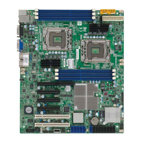
The following items are included in the retail box. • One (1) Supermicro Mainboard • Eight (8) Serial ATA cables (CBL-0044L) (For X8DTL-6/6F) • One (1) I/O backpanel shield (MCP-260-00027-ON) • One (1) Supermicro CD containing drivers and utilities •... - Page 10 X8DTL-6/X8DTL-6F/X8DTL-L/X8DTL-6L User's Manual X8DTL-6/X8DTL-6F/X8DTL-L/X8DTL-6L Image Note: The drawings and pictures shown in this manual were based on the latest PCB Revision available at the time of publishing of the manual. The motherboard you’ve received may or may not look exactly the same as...
- Page 11 Notes SAS Ports, SAS jumpers, and the LSI SAS2 2008 chip are available on the X8DTL-6/-6F/-6L only. For SAS RAID confi guration, refer to the LSI User Guide posted on our website @ http://www.supermicro.com/support/manuals/ IPMI 2.0, the PHY chip, and the Dedicated LAN (w/KVM support) are avail- able on the X8DTL-6F only.
- Page 12 X8DTL-6/X8DTL-6F/X8DTL-L/X8DTL-6L User's Manual Quick Reference P1-DIMM3A FAN1/ JPW3 JPW2 CPU1 FAN P1-DIMM2A P1-DIMM1A JPW1 Chip CPU1 CPU2 FAN2/ CPU2FAN X8DTL-6F Series FAN3 Rev. 1.3 CTRL P2-DIMM1A P2-DIMM2A CTRL P2-DIMM3A Slot6 PCI-E 2.0 x8 (in x16 Slot) Slot5 PCI-E 2.0 x4 (in x8 Slot)
- Page 13 Chapter 1: Introduction X8DTL-6/X8DTL-6F/X8DTL-L/X8DTL-6L Quick Reference Jumper Description Default Setting JBT1 CMOS Clear Open (Normal) C1/JI SMB to PCI/PCI-E Slots Open/Open (Disabled) JPG1 VGA Enable Pins 1-2 (Enabled) JPL1/JPL2 LAN1/2 Enable Pins 1-2 (Enabled) JPRST1 Alarm Reset Enable Pins 1-2 (Enabled)
-
Page 14: Motherboard Features
Two PCI-E 2.0 x4 (in x8) slots (Slots 4/5) • One PCI-E 1.0 x4 (in x8) (Slot 3) • Two 32-bit PCI MHz 33 slot (Slot 1 and Slot 2) (X8DTL-6/6F only) BIOS • 4 GB AMI SPI Flash ROM •... - Page 15 Windows OS and RAID0, RAID1, RAID10 in the Linux plat- forms) (Note 1) • LSI SAS2 2008 supports eight SAS ports support RAID0, RAID1, RAID10, and optional RAID5 w/AOC-IMRRAKey-2008-LSI (For X8DTL-6/-6F) (Note 2) • Dual 82574L Gigabit Ethernet controllers support Gigabit LAN1/2 ports •...
- Page 16 X8DTL-6/X8DTL-6F/X8DTL-L/X8DTL-6L User's Manual CPU1 CPU2 LGA1366 LGA1366 PORT1 PORT0 Gen2 Gen2 PORT PORT IOH-24D Intel 5500 PORT SAS #0 Gen2 SAS #1 PORT 9,10 CLINK SAS #2 SAS #3 SAS #4 ATMEL Gen1 Gen2 SAS #5 SAS2008/ AT25DF321 SAS #6...
-
Page 17: Chipset Overview
Chapter 1: Introduction Chipset Overview Built upon the functionality and the capability of the 5500 platform, the X8DTL-6/ X8DTL-6F/X8DTL-L/X8DTL-6L motherboard provides the performance and feature set required for dual-processor-based high-end systems optimized for HCP/Cluster systems and intensive applications. The 5500 platform consists of the 5500 Series (LGA 1366) processor, the 5500 (IOH-24D), and the ICH10R (South Bridge). -
Page 18: Special Features
To avoid possible system overheating, be sure to provide adequate airfl ow to the system. System Resource Alert This feature is available when used with Supero Doctor III in the Windows OS environment or used with Supero Doctor II in Linux. Supero Doctor is used to 1-10... -
Page 19: Acpi Features
Chapter 1: Introduction notify the user of certain system events. For example, you can also confi gure Supero Doctor to provide you with warnings when the system temperature, CPU temperatures, voltages and fan speeds go beyond a pre-defi ned range. -
Page 20: Power Supply
It is even more important for processors that have high CPU clock rates. The X8DTL-6/X8DTL-6F/X8DTL-L/X8DTL-6L can accommodate 24-pin ATX power supplies. Although most power supplies generally meet the specifi cations required by the CPU, some are inadequate. In addition, the two 12V 8-pin power connections are also required to ensure adequate power supply to the system. -
Page 21: Overview Of The Winbond Wpcm450R Controller (For X8Dtl-6F Only)
Chapter 1: Introduction ment through an SMI or SCI function pin. It also features auto power management to reduce power consumption. Overview of the Winbond WPCM450R Controller (For X8DTL-6F Only) The Winbond WPCM450R Controller is a Baseboard Management Controller (BMC) that supports the 2D/VGA-compatible Graphics Core with the PCI interface, Virtual Media, and Keyboard/Video/Mouse Redirection (KVMR) modules. - Page 22 X8DTL-6/X8DTL-6F/X8DTL-L/X8DTL-6L User's Manual Notes 1-14...
-
Page 23: Chapter 2 Installation
Chapter 2: Installation Chapter 2 Installation Static-Sensitive Devices Electrostatic Discharge (ESD) can damage electronic com ponents. To prevent dam- age to your system board, it is important to handle it very carefully. The following measures are generally suffi cient to protect your equipment from ESD. Precautions •... -
Page 24: Motherboard Installation
X8DTL-6/X8DTL-6F/X8DTL-L/X8DTL-6L User's Manual Motherboard Installation All motherboards have standard mounting holes to fi t different types of chassis. Make sure that the locations of all the mounting holes for both motherboard and chassis match. Although a chassis may have both plastic and metal mounting fasteners, metal ones are highly recommended because they ground the mother- board to the chassis. -
Page 25: Processor And Heatsink Installation
Chapter 2: Installation Processor and Heatsink Installation When handling the processor package, avoid placing direct pressure on the label area of the fan. Notes: Always connect the power cord last and always remove it before adding, re- moving or changing any hardware components. Make sure that you install the processor into the CPU socket before you install the CPU heatsink. - Page 26 X8DTL-6/X8DTL-6F/X8DTL-L/X8DTL-6L User's Manual After removing the plastic cap, using your thumb and the index fi nger, hold the CPU at the north and south center edges. Align the CPU key, the semi- circle cutout, against the socket key, the notch below the gold color dot on the side of the socket.
-
Page 27: Installing A Cpu Heatsink
Chapter 2: Installation Installing a CPU Heatsink Do not apply any thermal grease to the heatsink or the CPU die because the required amount has already been ap- plied. Screw#1 Screw#2 Place the heatsink on top of the CPU so that the four mounting holes are aligned with those on the retention mechanism. - Page 28 X8DTL-6/X8DTL-6F/X8DTL-L/X8DTL-6L User's Manual Removing the Heatsink Warning: We do not recommend that the CPU or the heatsink be re- moved. However, if you do need to remove the heatsink, please follow the instructions below to uninstall the heatsink and prevent damage to the CPU or other components.
-
Page 29: Installing And Removing The Memory Modules
Chapter 2: Installation Installing and Removing the Memory Modules Note: Check the Supermicro website for recommended memory modules. CAUTION Exercise extreme care when installing or removing DIMM modules to prevent any possible damage. Installing & Removing DIMMs Insert the desired number of DIMMs into the memory slots, starting with P1- DIMM1A. - Page 30 X8DTL-6/X8DTL-6F/X8DTL-L/X8DTL-6L User's Manual Memory Support The X8DTL-6F Series motherboard supports up to 24 GB of DDR3 Reg. ECC Memory or up to 12 GB of DDR3 Unbuffered ECC/Non-ECC 1333 MHz/1066 MHz/800 MHz memory in six DIMMs (with max. 4 GB of Registered ECC and 2 GB of Unbuffered memory per DIMM slot.)
- Page 31 Chapter 2: Installation Possible System Memory Allocation & Availability System Device Size Physical Memory Remaining (-Available) (4 GB Total System Memory) Firmware Hub fl ash memory (System BIOS) 1 MB 3.99 GB Local APIC 4 KB 3.99 GB Area Reserved for the chipset 2 MB 3.99 GB I/O APIC (4 Kbytes)
-
Page 32: Control Panel Connectors/Io Ports
X8DTL-6/X8DTL-6F/X8DTL-L/X8DTL-6L User's Manual Control Panel Connectors/IO Ports The I/O ports are color coded in conformance with the PC 99 specifi cation. See the picture below for the colors and locations of the various I/O ports. 1. Back Panel Connectors/IO Ports X8DTL-6F Series Rev. - Page 33 Chapter 2: Installation ATX PS/2 Keyboard and PS/2 PS/2 Keyboard/Mouse Pin Mouse Ports Defi nitions PS2 Keyboard PS2 Mouse The ATX PS/2 keyboard and PS/2 Pin# Defi nition Pin# Defi nition mouse are located next to the Back KB Data Mouse Data Panel USB Ports 0~1 on the moth- No Connection...
-
Page 34: Universal Serial Bus (Usb)
X8DTL-6/X8DTL-6F/X8DTL-L/X8DTL-6L User's Manual Universal Serial Bus (USB) Back Panel USB Front Panel USB (USB 0/1) (USB 6) Two Universal Serial Bus ports (USB Pin# Defi nitions Pin# Defi nition 0 and USB 1) are located on the I/O back panel. Additionally, fi ve USB con-... -
Page 35: Serial Ports
Chapter 2: Installation Serial Ports Serial Ports-COM1/COM2 Pin Defi nitions Two COM connections (COM1 & Pin # Defi nition Pin # Defi nition COM2) are located on the motherboard. COM1 is located on the Backplane IO panel. COM2 is located next to the onboard buzzer to provide additional serial connection support. -
Page 36: Ethernet Ports
X8DTL-6/X8DTL-6F/X8DTL-L/X8DTL-6L User's Manual Ethernet Ports LAN Ports Pin Defi nition Two Ethernet ports (LAN 1/LAN2) are Pin# Defi nition located at on the IO backplane. In ad- P2V5SB SGND dition, an IPMI_Dedicated LAN is also TD0+ Act LED located on the X8DTL-6F/-6 to provide... -
Page 37: Front Control Panel
Chapter 2: Installation 2. Front Control Panel JF1 contains header pins for various buttons and indicators that are normally lo- cated on a control panel at the front of the chassis. These connectors are designed specifi cally for use with Supermicro server chassis. See the fi gure below for the descriptions of the various control panel buttons and LED indicators. -
Page 38: Front Control Panel Pin Defi Nitions
X8DTL-6/X8DTL-6F/X8DTL-L/X8DTL-6L User's Manual 3. Front Control Panel Pin Defi nitions NMI Button NMI Button The non-maskable interrupt button Pin Defi nitions (JF1) header is located on pins 19 and 20 Pin# Defi nition of JF1. Refer to the table on the right Control for pin defi... -
Page 39: Hdd Led
Chapter 2: Installation HDD LED HDD LED The HDD LED connection is located Pin Defi nitions (JF1) on pins 13 and 14 of JF1. Attach a Pin# Defi nition cable here to indicate HDD/SATA activities generated from the ICH10R HD Active South Bridge. -
Page 40: Overheat (Oh)/Fan Fail/Front Uid Led
X8DTL-6/X8DTL-6F/X8DTL-L/X8DTL-6L User's Manual Overheat (OH)/Fan Fail/Front UID OH/Fan Fail LED Pin Defi nitions (JF1) Pin# Defi nition Connect an LED cable to the Front Vcc/Front UID LED UID and OH/Fan Fail connections on OH/Fan Fail LED pins 7 and 8 of JF1 to display UID... -
Page 41: Reset Button
Chapter 2: Installation Reset Button Reset Button The Reset Button connection is located Pin Defi nitions (JF1) on pins 3 and 4 of JF1. Attach it to a Pin# Defi nition hardware reset switch on the computer Reset case. Refer to the table on the right for Ground pin defi... -
Page 42: Connecting Cables
X8DTL-6/X8DTL-6F/X8DTL-L/X8DTL-6L User's Manual Connecting Cables ATX Power 24-pin Connector Pin Defi nitions Pin# Defi nition Pin # Defi nition Power Connectors +3.3V +3.3V -12V +3.3V A 24-pin main power supply connector(JPW1) and two 8-pin CPU PWR connectors (JPW2/ PS_ON JPW3) on the motherboard. These power connectors meet the SSI EPS 12V specifi... -
Page 43: Fan Headers
Chapter 2: Installation Fan Headers Fan Header This motherboard has six CPU/system Pin Defi nitions cooling fans on the motherboard. (Fan Pin# Defi nition 1/Fan 2 are CPU fans.) All these 4-pin Ground fans headers are backward compatible +12V with the traditional 3-pin fans. However, Tachometer fan speed control is available for 4-pin PWR Modulation... -
Page 44: Internal Speaker
X8DTL-6/X8DTL-6F/X8DTL-L/X8DTL-6L User's Manual Internal Speaker Internal Buzzer (SP1) Pin Defi nition The Internal Speaker, located at SP1, Pin# Defi nitions provides audible indications for vari- Pin 1 Pos. (+) Beep In ous beep codes. See the table on the Pin 2 Neg. -
Page 45: Wake-On-Lan
Chapter 2: Installation Wake-On-LAN Wake-On-LAN Pin Defi nitions The Wake-On-LAN header is located at Pin# Defi nition JWOL on the motherboard. You must also +5V Standby have a LAN card with a Wake-On-LAN con- Ground nector and a cable to use this feature. See Wake-up the table on the right for pin defi... -
Page 46: T-Sgpio 1/2 & 3-Sgpio 1/2 Headers
Data motherboard. Two additional GPIO Load Ground connections (3-GPIO 1/2) are also located on the X8DTL-6/-6L models. Note: NC= No Connections These headers support serial link interfaces for the onboard SATA and SAS connectors. See the table on the right for pin defi nitions. Refer to the board layout below for the location. -
Page 47: Power Smb (I 2 C) Connector
Chapter 2: Installation Power SMB (I C) Connector PWR SMB Pin Defi nitions Power System Management Bus (I Pin# Defi nition Connector (JPI C) monitors power Clock supply, fan and system temperatures. Data See the table on the right for pin PWR Fail defi... -
Page 48: Unit Identifi Cation Switch/Leds
X8DTL-6/X8DTL-6F/X8DTL-L/X8DTL-6L User's Manual Unit Identifi cation Switch/LEDs UID Switch There are three Unit Identifi cation (UID) de- Pin# Defi nition vices on the motherboard. A rear UID switch Ground and a rear UID LED indicator are located Ground next to Fan 6 on the back of the chassis. -
Page 49: Jumper Settings
Chapter 2: Installation Jumper Settings Explanation of Jumpers Connector Pins To modify the operation of the mother- board, jumpers can be used to choose between optional settings. Jumpers cre- Jumper ate shorts between two pins to change the function of the connector. Pin 1 is identifi... -
Page 50: Cmos Clear
X8DTL-6/X8DTL-6F/X8DTL-L/X8DTL-6L User's Manual CMOS Clear JBT1 is used to clear CMOS. Instead of pins, this "jumper" consists of contact pads to prevent the accidental clearing of CMOS. To clear CMOS, use a metal object such as a small screwdriver to touch both pads at the same time to short the connection. -
Page 51: I 2 C Bus To Pci-Exp. Slots
Chapter 2: Installation C Bus to PCI-Exp. Slots C for PCI/PCI-E slots Jumpers JI C1 and JI C2 allow you to Jumper Settings connect the System Management Bus Jumper Setting Defi nition C) to PCI and PCI-Express slots. Closed Enabled These two jumpers are to be set at the Open Disabled (Default) -
Page 52: Sas Enable/Disable (X8Dtl-6/6F/6L Only)
X8DTL-6/X8DTL-6F/X8DTL-L/X8DTL-6L User's Manual SAS Enable/Disable (X8DTL-6/6F/6L SAS Enable Jumper Settings only) Jumper Setting Defi nition Jumper JPS1 allows you to enable or disable SAS Enabled (Default) the onboard SAS connections. The default SAS Disabled setting is Pins 1-2 to enable the connec- tion. -
Page 53: Alarm Reset
Chapter 2: Installation Alarm Reset Alarm Reset Jumper Settings If three power supplies are installed Pin Setting Defi nition and Alarm Reset (JPRST1) is enabled, Enable the system will notify you when any of Disable the three power modules fails. Connect JPRST1 to a micro-switch to enable you to turn off the alarm that is activated when a power module fails. -
Page 54: Onboard Led Indicators
X8DTL-6/X8DTL-6F/X8DTL-L/X8DTL-6L User's Manual Onboard LED Indicators Activity LED Link LED GLAN LEDs Rear View (when facing the Two LAN ports (LAN 1/LAN 2) are located rear side of the chassis) on the IO Backplane of the motherboard. LAN 1/LAN 2 Activity LED (Left) -
Page 55: Bmc Heartbeat Led (X8Dtl-6F)
BMC: Normal ing, BMC functions normally. See the tables at right for more information. SAS Heartbeat LED & SAS Error LED SAS Heartbeat LED Indicators (X8DTL-6/-6F/-6L) Settings (DS7) LED Color Defi nition An Onboard SAS Heartbeat LED is lo- Green (Blinking) SAS: Normal cated at DS7 on the motherboard. -
Page 56: Onboard Power Led
X8DTL-6/X8DTL-6F/X8DTL-L/X8DTL-6L User's Manual Onboard Power LED Onboard PWR LED (LE1) An Onboard Power LED is located at LE1 Settings on the motherboard. When this LED is lit, LED Color Defi nition the system is on. Be sure to turn off the... -
Page 57: Chapter 3 Troubleshooting
Chapter 3: Troubleshooting Chapter 3 Troubleshooting Troubleshooting Procedures Use the following procedures to troubleshoot your system. If you have followed all of the procedures below and still need assistance, refer to the ‘Technical Support Procedures’ and/or ‘Returning Merchandise for Service’ section(s) in this chapter. Note: Always disconnect the power cord before adding, changing or installing any hardware components. -
Page 58: No Video
X8DTL-6/X8DTL-6F/X8DTL-L/X8DTL-6L User's Manual No Video If the power is on but you have no video, remove all the add-on cards and cables. Use the speaker to determine if any beep codes exist. Refer to the Appendix for details on beep codes. -
Page 59: Technical Support Procedures
Question: What are the various types of memory that my motherboard can support? Answer: The X8DTL-6/X8DTL-6F/X8DTL-L/X8DTL-6L supports up to 24 GB of DDR3 Reg. ECC or up to 12 GB of DDR3 Unbuffered ECC/Non-ECC 1333 MHz/1066 MHz/800 MHz memory (with max. 4 GB of Registered ECC and 2 GB of Unbuffered memory per DIMM slot) in six DIMM slots. -
Page 60: Returning Merchandise For Service
X8DTL-6/X8DTL-6F/X8DTL-L/X8DTL-6L User's Manual Question: How do I update my BIOS? Answer: It is recommended that you do not upgrade your BIOS if you are not experiencing any problems with your system. Updated BIOS fi les are located on our website at http://www.supermicro.com/support/bios/. Please check our BIOS warning message and the information on how to update your BIOS on our web- site. -
Page 61: Chapter 4 Bios
Chapter 4 BIOS Introduction This chapter describes the AMI BIOS Setup Utility for the X8DTL-6/X8DTL-6F/ X8DTL-L/X8DTL-6L motherboard. The AMI ROM BIOS is stored in a Flash EE- PROM and can be easily updated. This chapter describes the basic navigation of the AMI BIOS Setup Utility setup screens. -
Page 62: How To Change The Confi Guration Data
X8DTL-6/X8DTL-6F/X8DTL-L/X8DTL-6L User's Manual How To Change the Confi guration Data The confi guration data that determine the system parameters may be changed by entering the AMI BIOS Setup utility. This Setup utility can be accessed by pressing <Del> at the appropriate time during system boot. - Page 63 Chapter 4: AMI BIOS System Time/System Date Use this option to change the system time and date. Highlight System Time or Sys- tem Date using the arrow keys. Key in new values through the keyboard and press <Enter>. Press the <Tab> key to move between fi elds. The date must be entered in MM/DD/YY format.
-
Page 64: Advanced Setup Confi Gurations
X8DTL-6/X8DTL-6F/X8DTL-L/X8DTL-6L User's Manual Advanced Setup Confi gurations Use the arrow keys to select Boot Setup and hit <Enter> to access the submenu items. Boot Features Quick Boot If enabled, this option will skip certain tests to reduce the time needed for system boot. - Page 65 Chapter 4: AMI BIOS Wait For 'F1' If Error This forces the system to wait until the <F1> key is pressed if an error occurs. The options are Disabled and Enabled. Hit 'Del' Message Display If this feature is set to Enabled, the message: "Press DEL to run Setup" will be displayed during POST.
- Page 66 X8DTL-6/X8DTL-6F/X8DTL-L/X8DTL-6L User's Manual Ratio CMOS Setting (Available when the item-CPU Ratio is set to Manual) Press <+> or <-> on your keyboard to set the ratio between the CPU Core clock and the FSB Frequency. The default setting is [19].
- Page 67 Chapter 4: AMI BIOS Simultaneous Multi-Threading (Available when supported by the CPU) Set to Enabled to use the Simultaneous Multi-Threading Technology to enhance CPU performance. The options are Disabled and Enabled. Active Processor Cores Set to Enabled to use a processor's Second Core and beyond. (Please refer to Intel's website for more information.) The options are All, 1, and 2.
- Page 68 X8DTL-6/X8DTL-6F/X8DTL-L/X8DTL-6L User's Manual ACPI T State Select Enabled to report CPU throttling state in ACPI. The options are Enabled and Disabled. DCA Technology Select Enabled to enhance the performance of a TOE device, which is a special- ized, dedicated processor installed on an add-on card to handle some or all packet processing of this add-on card.
- Page 69 Chapter 4: AMI BIOS Memory Mode The options are Independent, Channel Mirror, and Lockstep. Independent - All DIMMs are available to the operating system. Channel Mirror - The motherboard maintains two identical copies of all data in memory for redundancy. Lockstep - The motherboard uses two areas of memory to run the same set of operations in parallel.
- Page 70 X8DTL-6/X8DTL-6F/X8DTL-L/X8DTL-6L User's Manual Temp. Rise (Closed Loop/Open Loop)) This is the temperature rise used for the DIMM thermal zone. Each step is in C increments. The default is [020]. Press <+> or <-> on your keyboard to change this value.
- Page 71 Chapter 4: AMI BIOS Active State Power Management Select Enabled to use Active-State Power Management for signal transactions between L0 and L1 Links on the PCI Express Bus. This maximizes power-saving and transaction speed. The options are Enabled and Disabled. USB Functions This feature allows the user to decide the number of onboard USB ports to be en- abled.
- Page 72 X8DTL-6/X8DTL-6F/X8DTL-L/X8DTL-6L User's Manual SATA#2 Confi guration (Available when "IDE" is selected) Selecting Enhanced will set SATA#2 to native SATA mode. The options are Disabled, and Enhanced. IDE Detect Timeout (sec) Use this feature to set the time-out value for the BIOS to detect the ATA and ATAPI devices installed in the system.
- Page 73 Chapter 4: AMI BIOS Select 1 to allow the AMI BIOS to use PIO mode 1. It has a data transfer rate of 5.2 MB/s. Select 2 to allow the AMI BIOS to use PIO mode 2. It has a data transfer rate of 8.3 MB/s.
- Page 74 X8DTL-6/X8DTL-6F/X8DTL-L/X8DTL-6L User's Manual Select UDMA6 to allow the BIOS to use Ultra DMA mode 6. It has a data transfer rate of 133 MB/s. The options are Auto, SWDMAn, MWDMAn, and UDMAn. S.M.A.R.T. For Hard disk drives Self-Monitoring Analysis and Reporting Technology (SMART) can help predict impending drive failures.
- Page 75 Chapter 4: AMI BIOS Slot 1 PCI 33MHz, Slot 2 PCI 33MHz, Slot 3 PCIE x4 1.0 in X8 Slot, Slot 4 PCIE 2.0 x4 in x8 Slot, Slot 5 PCIE x4 in x8 Slot, Slot 6 PCIE x8 in x16 Slot This feature allows you to Enable or Disable any of the PCI slots.
- Page 76 X8DTL-6/X8DTL-6F/X8DTL-L/X8DTL-6L User's Manual Serial Port Number This feature allows the user decide which serial port to be used for Console Re- direction. The options are COM 1 and COM 2. (When BMC is present, COM2 will be enabled for SOL.) Base Address, IRQ This item displays the based address and IRQ of the serial port specifi...
- Page 77 Chapter 4: AMI BIOS CPU Overheat Alarm This option allows the user to select the CPU Overheat Alarm setting which de- termines when the CPU OH alarm will be activated to provide warning of possible CPU overheat. Warning! 1.Any temperature that exceeds the CPU threshold tempera- ture predefi...
- Page 78 X8DTL-6/X8DTL-6F/X8DTL-L/X8DTL-6L User's Manual prevent damage to the CPU. User intervention: If the system buzzer and Overheat LED has activated, take action immediately by checking the system fans, chassis ventilation and room temperature to correct any problems. Notes: 1. The CPU thermal technology that reports absolute temperatures (Celsius/ Fahrenheit) has been upgraded to a more advanced feature by Intel in its newer processors.
- Page 79 Chapter 4: AMI BIOS Voltage Readings The following voltage readings will be displayed. CPU1 Vcore, CPU2 Vcore, 1.5V, 5V, 5VSB, 12V, -12V, 3.3Vcc, 3.3VSB, VBAT and Vtt ACPI Confi guration Use this feature to confi gure Advanced Confi guration and Power Interface (ACPI) power management settings for your system.
- Page 80 X8DTL-6/X8DTL-6F/X8DTL-L/X8DTL-6L User's Manual tem. The options are ACPI v1.0, ACPI v2.0 and ACPI v3.0. For more information, please refer to ACPI's website at http://www.acpi.info/. Trusted Computing TCG/TPM (Trusted Platform Module) Support Select Yes on this item and enable the TPM jumper on the motherboard to enable TCG (TPM 1.1/1.2)/TPM support in order to improve data integrity and network...
- Page 81 Chapter 4: AMI BIOS IPMI Confi guration Intelligent Platform Management Interface (IPMI) is used to monitor and manage the system from a remote site. For more information, please visit Intel's website at www.intel.com. IPMI Firmware Revision This item displays the current IPMI fi rmware revision. Status of BMC Baseboard Management Controller (BMC) manages the interface between system management software and platform hardware.
- Page 82 X8DTL-6/X8DTL-6F/X8DTL-L/X8DTL-6L User's Manual Caution: Make sure that you no longer need any data stored in the event log before clearing the BMC Event Log because you will not be able to recover any data included in the event log once you've "cleared" it.
-
Page 83: Security Settings
Chapter 4: AMI BIOS BMC Watch Dog TimeOut [Min:Sec] This option appears if BMC Watch Dog Timer Action is not set to Disabled. This is a timed delay in minutes or seconds before a system power-down or system reset after an operating system failure is detected. The options are [5 Min], [1 Min], [30 Sec], and [10 Sec]. - Page 84 X8DTL-6/X8DTL-6F/X8DTL-L/X8DTL-6L User's Manual Supervisor Password This item indicates if a Supervisor password has been entered for the system. "Not Installed" means a Supervisor password has not been used. User Password This item indicates if a user password has been entered for the system. "Not In- stalled"...
-
Page 85: Boot Confi Guration
Chapter 4: AMI BIOS Boot Confi guration Use this feature to confi gure boot settings. Boot Device Priority This feature allows the user to specify the sequence of priority for the Boot Device. The settings are 1st boot device, 2nd boot device, 3rd boot device, 4th boot device, 5th boot device and Disabled. -
Page 86: Exit Options
X8DTL-6/X8DTL-6F/X8DTL-L/X8DTL-6L User's Manual Retry Boot Devices If this feature is enabled, the system will continue to search for the next boot device if the current boot device is not available. The options are Enabled, and Disabled. Exit Options Select the Exit tab from the BIOS Setup menu to enter the Exit Setup screen. -
Page 87: Appendix A Bios Error Beep Codes
Appendix A: BIOS POST Error Codes Appendix A BIOS Error Beep Codes During the POST (Power-On Self-Test) routines, which are performed each time the system is powered on, errors may occur. Non-fatal errors are those which, in most cases, allow the system to continue the boot-up process. - Page 88 X8DTL-6/X8DTL-6F/X8DTL-L/X8DTL-6L User's Manual Notes...
-
Page 89: Appendix B Software Installation Instructions
Appendix B: Software Installation Instructions Appendix B Software Installation Instructions B-1 Installing Software Programs After you've installed the operating system, a screen as shown below will appear. You are ready to install software programs and drivers that have not yet been installed. - Page 90 The Supero Doctor III program is a Web-base management tool that supports remote management capability. It includes Remote and Local Management tools. The local management is called the SD III Client. The Supero Doctor III program included on the CDROM that came with your motherboard allows you to monitor the environment and operations of your system.
- Page 91 Appendix B: Software Installation Instructions Supero Doctor III Interface Display Screen-II (Remote Control) Note: SD III Software Revision 1.0 can be downloaded from our Web site at: ftp://ftp.supermicro.com/utility/Supero_Doctor_III/. You can also download SDIII User's Guide at: http://www.supermicro.com/PRODUCT/ Manuals/SDIII/UserGuide.pdf. For Linux, we will still recommend that you...
- Page 92 X8DTL-6/X8DTL-6F/X8DTL-L/X8DTL-6L User's Manual Notes...
- Page 93 (Disclaimer Continued) The products sold by Supermicro are not intended for and will not be used in life support systems, medical equipment, nuclear facilities or systems, aircraft, aircraft devices, aircraft/emergency communication devices or other critical systems whose failure to perform be reasonably expected to result in signifi cant injury or loss of life or catastrophic property damage.
Need help?
Do you have a question about the X8DTL-6 and is the answer not in the manual?
Questions and answers