Table of Contents
Advertisement
Quick Links
Advertisement
Table of Contents

Related Manuals for Supero X10DGO-T


Summary of Contents for Supero X10DGO-T
- Page 1 X10DGO-T X10DGO-SXM USER’S MANUAL Revision 1.0a...
- Page 2 The information in this user’s manual has been carefully reviewed and is believed to be accurate. The vendor assumes no responsibility for any inaccuracies that may be contained in this document, and makes no commitment to update or to keep current the information in this manual, or to notify any person or organization of the updates.
-
Page 3: About This Motherboard
Preface Preface This manual is written for system integrators, IT professionals, and knowledgeable end users. It provides information for the installation and use of the X10DGO(-T/-SXM) motherboard. About This Motherboard T h e S u p e r m i c r o X 1 0 D G O ( - T / - S X M ) m o t h e r b o a r d s u p p o r t s... -
Page 4: Conventions Used In The Manual
X10DGO(-T/-SXM) Motherboard User’s Manual Conventions Used in the Manual Pay special attention to the following symbols for proper system installation: Warning: Important information given to ensure proper system installation or to prevent damage to the components or injury to yourself; Note: Additional information given to differentiate between models or instructions provided for proper system setup. -
Page 5: Contacting Supermicro
Preface Contacting Supermicro Headquarters Address: Super Micro Computer, Inc. 980 Rock Ave. San Jose, CA 95131 U.S.A. Tel: +1 (408) 503-8000 Fax: +1 (408) 503-8008 Email: marketing@supermicro.com (General Information) support@supermicro.com (Technical Support) Website: www.supermicro.com Europe Address: Super Micro Computer B.V. Het Sterrenbeeld 28, 5215 ML 's-Hertogenbosch, The Netherlands Tel:... -
Page 6: Table Of Contents
X10DGO(-T/-SXM) Motherboard User’s Manual Table of Contents Preface About This Motherboard ....................3 Manual Organization ..................... 3 Conventions Used in the Manual .................. 4 Contacting Supermicro ....................5 Chapter 1 Overview Overview ......................1-1 Checklist ......................1-1 Motherboard Features ..................1-9 Processor and Chipset Overview.............. - Page 7 Table of Contents Installing and Removing the Memory Modules ..........2-13 Installing Memory Modules ................2-13 Removing Memory Modules ................. 2-13 Control Panel Connectors and I/O Ports ............2-16 Front Panel Connectors and I/O Ports ............2-16 Front Panel I/O Port Locations and Definitions ........... 2-16 Ethernet Ports ..................
- Page 8 X10DGO(-T/-SXM) Motherboard User’s Manual No Video ......................3-2 System Boot Failure ..................3-2 Losing the System’s Setup Configuration ............3-2 Memory Errors ....................3-3 When the System Becomes Unstable ............3-3 Technical Support Procedures ................ 3-5 Battery Removal and Installation ..............3-6 Battery Removal ....................
-
Page 9: Chapter 1 Overview
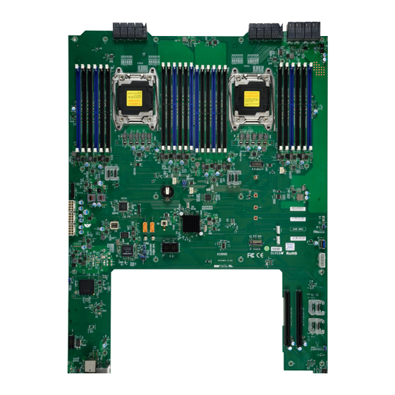
Chapter 1: Overview Chapter 1 Overview Overview Checklist Congratulations on purchasing your computer motherboard from an acknowledged leader in the industry. Supermicro boards are designed with the utmost attention to detail to provide you with the highest standards in quality and performance. The X10DGO(-T/-SXM) motherboard was designed to be used with a Supermicro- proprietary chassis as an integrated server platform. - Page 10 X10DGO(-T/-SXM) Motherboard User’s Manual X10DGO Motherboard Image Note: All graphics shown in this manual were based upon the latest PCB Revision available at the time of publishing of the manual. The motherboard you've received may or may not look exactly the same as the graphics shown in this manual.
- Page 11 Chapter 1: Overview X10DGO Motherboard Layout PRESS FIT PRESS FIT PRESS FIT PRESS FIT PRESS FIT PRESS FIT PRESS FIT PRESS FIT JMP8 JMP7 JMP6 JMP5 JMP4 JMP3 JMP2 JMP1 JPWR2 JPWR1 CPU1 CPU2 CLOSE 1st CLOSE 1st OPEN 1st OPEN 1st JITP1 CPU2...
- Page 12 X10DGO(-T/-SXM) Motherboard User’s Manual X10DGO-SXM Image...
- Page 13 Chapter 1: Overview X10DGO-SXM Layout FAN4 FAN2 FAN1 GPU3 GPU2 GPU6 GPU7 GPU8 GPU5 GPU1 GPU4 JCPLD1 X10DGO-SXM BAR CODE REV:1.01 DESIGNED IN USA JMP1 JMP2 JMP3 JMP4 JMP5 JMP6 JMP7 JMP8 PRESS FIT PRESS FIT PRESS FIT PRESS FIT PRESS FIT PRESS FIT PRESS FIT...
- Page 14 X10DGO(-T/-SXM) Motherboard User’s Manual X10DGO Quick Reference PRESS FIT PRESS FIT PRESS FIT PRESS FIT PRESS FIT PRESS FIT PRESS FIT PRESS FIT JMP8 JMP7 JMP6 JMP5 JMP4 JMP3 JMP2 JMP1 JPWR2 JPWR1 CPU1 CPU2 CLOSE 1st CLOSE 1st OPEN 1st OPEN 1st JITP1 CPU2...
- Page 15 Power for HDD Backplane JPWR1/JPWR2 Midplane Power Connector JSD1/JSD2 Power Connector SATA DOM JTPM1 TPM (Trusted Platform Module)/Port 80 Header (IPMI) LAN Dedicated IPMI LAN Port X540-based 10G Ethernet LAN Ports 1/2 (X10DGO-T); I350-based 1G LAN1/LAN2 LAN Ports 1/2 (X10DGO)
- Page 16 X10DGO(-T/-SXM) Motherboard User’s Manual (I-)SATA0~3 Intel® SATA 3.0 Connectors from Intel® PCH SATA controller (I-)SATA4/5 Intel® SATA SuperDOM Connectors from Intel® PCH (S)-SATA0~3 SATA Connectors 3.0 from Intel® PCH sSATA controller SLOT1 PCI-Express 3.0 x8 Slot supported by CPU2 SLOT2 PCI-Express 3.0 x8 Slot supported by CPU1 USB0 Internal USB 3.0 Type A Connector...
-
Page 17: Motherboard Features
One Intel i350 Gigabit (10/100/1000 Mb/s) Ethernet Dual-Channel Controller for LAN 1/LAN 2 ports (X10DGO) • One Intel X540 Dual-Channel Controller for 10G- based-T LAN 1/LAN 2 ports (X10DGO-T) I/O Devices SATA Connections • SATA Ports Ten (10) SATA 3.0 ports •... - Page 18 X10DGO(-T/-SXM) Motherboard User’s Manual Peripheral USB Devices Devices • Two (2) USB 3.0 ports on the front panel (USB2/3) • One (1) USB 3.0 Internal USB type A (USB0) • BIOS 128Mb SPI AMI BIOS Flash ROM ® • ACPI 3.0, SMBIOS 2.7 or later, PCI/FW 3.0, BIOS rescue hot-key, RTC (Real Time Clock) wakeup •...
- Page 19 Chapter 1: Overview #H-3 #H-2 #H-1 #D-3 #G-3 DDR4 #D-2 #G-2 DDR4 VDDQ VR12.5 VR12.5 #D-1 #G-1 VDDQ 5 PHASE 5 PHASE #C-3 #F-3 #C-2 #F-2 #C-1 #F-1 #B-3 #E-3 DDR4 #B-2 #E-2 DDR4 #B-1 #E-1 CPU2 CPU1 #A-3 #A-2 9.6G DDR-IV DDR-IV...
-
Page 20: Processor And Chipset Overview
X10DGO(-T/-SXM) Motherboard User’s Manual Processor and Chipset Overview Built upon the functionality and capability of the dual Intel® Xeon EP E5-2600 v3/v4 series processors (Socket R3) and the Intel® PCH C612, the X10DGO(-T ) motherboard provides the best balanced solution of performance, power-efficien- cy, and features to address the diverse needs of next-generation computer users. -
Page 21: Special Features
Chapter 1: Overview Special Features Recovery from AC Power Loss The Basic I/O System (BIOS) provides a setting that determines how the system will respond when AC power is lost and then restored to the system. You can choose for the system to remain powered off (in which case you must press the power switch to turn it back on), or for it to automatically return to the power-on state. -
Page 22: System Resource Alert
X10DGO(-T/-SXM) Motherboard User’s Manual System Resource Alert This feature is available when used with SuperDoctor® 5. SuperDoctor® 5 is used to notify the user of certain system events. For example, you can configure SuperDoctor® 5 to provide you with warnings when the system temperature, CPU temperatures, voltages, and fan speeds go beyond a predefined range. -
Page 23: Intel ® Intelligent Power Node Manager (Ipnm) (Available When The Spm Utility Is Installed)
Chapter 1: Overview Intel ® Intelligent Power Node Manager (IPNM) (Available when the SPM Utility is Installed) The Intel® Intelligent Power Node Manager 3.0 (IPNM) provides your system with real-time thermal control and power management for maximum energy efficiency. Although IPNM Specification Version 2.0/3.0 is supported by the BMC (Baseboard Management Controller), your system must also have IPNM-compatible Manage- ment Engine (ME) firmware installed to use this feature. - Page 24 X10DGO(-T/-SXM) Motherboard User’s Manual Notes 1-16...
-
Page 25: Chapter 2 Installation
Chapter 2: Installation Chapter 2 Installation Standardized Warning Statements The following statements are industry-standard warnings, provided to warn the user of situations which have the potential for bodily injury. Should you have questions or experience difficulty, contact Supermicro's Technical Support department for assis- tance. - Page 26 X10DGO(-T/-SXM) Motherboard User’s Manual Attention Danger d'explosion si la pile n'est pas remplacée correctement. Ne la remplacer que par une pile de type semblable ou équivalent, recommandée par le fabricant. Jeter les piles usagées conformément aux instructions du fabricant. ¡Advertencia! Existe peligro de explosión si la batería se reemplaza de manera incorrecta.
-
Page 27: Product Disposal
Chapter 2: Installation Product Disposal Warning! Ultimate disposal of this product should be handled according to all national laws and regulations. 製品の廃棄 この製品を廃棄処分する場合、 国の関係する全ての法律 ・ 条例に従い処理する必要が あります。 警告 本产品的废弃处理应根据所有国家的法律和规章进行。 警告 本產品的廢棄處理應根據所有國家的法律和規章進行。 Warnung Die Entsorgung dieses Produkts sollte gemäß allen Bestimmungen und Gesetzen des Landes erfolgen. -
Page 28: Static-Sensitive Devices
X10DGO(-T/-SXM) Motherboard User’s Manual القىانين واللىائح الىطنية جميع وفقا ل ينبغي التعامل معه هذا المنتج من التخلص النهائي عند 경고! 이 제품은 해당 국가의 관련 법규 및 규정에 따라 폐기되어야 합니다. Waarschuwing De uiteindelijke verwijdering van dit product dient te geschieden in overeenstemming met alle nationale wetten en reglementen. -
Page 29: Motherboard Installation
Chapter 2: Installation Motherboard Installation All motherboards have standard mounting holes to fit different types of chassis. Make sure that the locations of all the mounting holes for both motherboard and chassis match. Although a chassis may have both plastic and metal mounting fas- teners, metal ones are highly recommended because they ground the motherboard to the chassis. -
Page 30: Installing The Motherboard
X10DGO(-T/-SXM) Motherboard User’s Manual Installing the Motherboard 1. Install the I/O shield into the chassis. 2. Locate the mounting holes on the motherboard. 3. Locate the matching mounting holes on the chassis. Align the mounting holes on the motherboard against the mounting holes on the chassis. 4. -
Page 31: Processor And Heatsink Installation
Chapter 2: Installation Processor and Heatsink Installation Warning: When handling the processor package, avoid placing direct pressure on the label area. Notes: • Always connect the power cord last, and always remove it before adding, re- moving or changing any hardware components. Make sure that you install the processor into the CPU socket before you install the CPU heatsink. - Page 32 X10DGO(-T/-SXM) Motherboard User’s Manual 2. Press the second load lever labeled 'Close 1st' to release the load plate that covers the CPU socket from its locking position. Pull lever away from Press down on Load the socket Lever 'Close 1st' 3.
- Page 33 Chapter 2: Installation 1. Use your thumb and the index finger to loosen the lever and open the load plate. 2. Using your thumb and index finger, hold the CPU on its edges. Align the CPU keys, which are semi-circle cutouts, against the socket keys. Socket Keys CPU Keys 3.
- Page 34 X10DGO(-T/-SXM) Motherboard User’s Manual 4. With the CPU inside the socket, inspect the four corners of the CPU to make sure that the CPU is properly installed. 5. Close the load plate with the CPU inside the socket. Lock the lever labelled 'Close 1st' first, then lock the lever labelled 'Open 1st' second.
-
Page 35: Installing A Passive Cpu Heatsink
Chapter 2: Installation Installing a Passive CPU Heatsink 1. Do not apply any thermal grease to the heatsink or the CPU die -- the re- quired amount has already been applied. 2. Place the heatsink on top of the CPU so that the four mounting holes are aligned with those on the Motherboard and the Heatsink Bracket underneath. -
Page 36: Removing The Heatsink
X10DGO(-T/-SXM) Motherboard User’s Manual Removing the Heatsink Warning: We do not recommend that the CPU or the heatsink be removed. However, if you do need to uninstall the heatsink, please follow the instructions below to uninstall the heatsink to prevent damage done to the CPU or the CPU socket. 1. -
Page 37: Installing And Removing The Memory Modules
Chapter 2: Installation Installing and Removing the Memory Modules Note: Check Supermicro's website for recommended memory modules. CAUTION Exercise extreme care when installing or removing DIMM modules to prevent any possible damage. Installing Memory Modules 1. Insert the desired number of DIMMs into the memory slots, starting with P1-DIMMA1. - Page 38 X10DGO(-T/-SXM) Motherboard User’s Manual Memory Support for the X10DGO Motherboard The X10DGO(-T/-SXM) motherboard supports up to 1536GB of LRDIMM (Load Reduced) and RDIMM (Registered) ECC/Non-ECC DDR4 (288-pin) memory at up to 2400MT/s in 24 DIMM slots. For the latest memory updates, please refer to our website at http://www.supermicro.com/products/motherboard.
- Page 39 Chapter 2: Installation Populating DDR4 DIMM Modules for the E5-2600 v3/v4-based Platform Populating RDIMM/LRDIMM DDR4 Memory Modules Speed (MT/s); Voltage (V); Slots per Channel (SPC) and DIMMs per Channel (DPC) Ranks 3 Slots per Channel DIMM Capacity DIMM (GB) 1 DPC 2 DPC 3 DPC Type...
-
Page 40: Control Panel Connectors And I/O Ports
X10DGO(-T/-SXM) Motherboard User’s Manual Control Panel Connectors and I/O Ports The I/O ports are color coded in conformance with the industry standards. See the picture below for the colors and locations of the various I/O ports. Front Panel Connectors and I/O Ports PRESS FIT PRESS FIT PRESS FIT... -
Page 41: Ethernet Ports
I/O front panel. TDR1+ TDR4+ These Ethernet ports support 1 GbE TDR1- TDR4- TRCT1 TRCT4 (X10DGO) or 10 GbE (X10DGO-T). TDR2+ IET+ In addition, a dedicated IPMI LAN is TDR2- IET- located above USB3/4 on the back TRCT2... -
Page 42: Universal Serial Bus (Usb)
X10DGO(-T/-SXM) Motherboard User’s Manual Universal Serial Bus (USB) Internal USB (3.0) 0 Two USB 3.0 ports (USB 2/3) are located Pin# Description on the I/O front panel. In addition, there VBUS is one internal USB 3.0 Type A connec- tor. See the tables on the right for pin definitions. -
Page 43: Video Connector
Chapter 2: Installation Video Connector A Video (VGA) connector is located on the I/O front panel. This connector is used to provide video and CRT display. Refer to the motherboard layout below for the location. Power Button Press this button to turn on the system. Reset Button Press this button to force the system to reset. -
Page 44: Connecting Cables
X10DGO(-T/-SXM) Motherboard User’s Manual Connecting Cables Power Connectors Midplane Power Connector (JPW2/JPW1) Two 48-pin (JPWR1/2) main power con- nectors are located on the motherboard. Pin # Definition Pin # Definition See the tables on the right for pin defini- B1[A:F] A1[A:F] B2[A:F] A2[A:F]... -
Page 45: Fan Headers
Chapter 2: Installation Fan Headers Fan Header Pin Definitions This motherboard has 3 system/CPU fan Pin# Definition headers (Fan 1 - Fan 3) on the mother- Ground board. All these 4-pin fans headers are +12V backward compatible with the traditional Tachometer 3-pin fans. -
Page 46: Tpm/Port 80 Header
X10DGO(-T/-SXM) Motherboard User’s Manual TPM/Port 80 Header TPM/Port 80 Header Pin Definitions A Trusted Platform Module/Port 80 Pin # Definition Pin # Definition header, located at JTPM1, provides TPM LCLK support and Port 80 connection. Use this LFRAME# <(KEY)> header to enhance system performance LRESET# +5V (X) and data security. -
Page 47: Slot
Chapter 2: Installation M.2 Slot M.2 is formerly known as Next Genera- tion Form Factor (NGFF). The M.2 slot is designed for internal mounting devices. The X10DGO (-T) motherboard deploys an M key only dedicated for SSD devices with the ultimate performance capability for native PCI-E SSD support. -
Page 48: Powered Sata Dom (Superdom) Connectors
X10DGO(-T/-SXM) Motherboard User’s Manual Powered SATA DOM (SuperDOM) SuperDOM Connector Connectors Pin Definitions Pin# Definition Two powered SATADOM (Device-on- Module) connectors are located at JSD1/ Ground JSD2 on the motherboard. These con- Ground nectors are used with Supermicro Super- DOMs, which are yellow SATA devices with power-pins built in, and can be used to provide backward-compatible power support to non-Supermicro SATADOMs... -
Page 49: Jumper Settings
Chapter 2: Installation Jumper Settings Explanation of Jumpers Connector Pins To modify the operation of the mother- board, jumpers can be used to choose between optional settings. Jumpers cre- Jumper ate shorts between two pins to change the function of the connector. Pin 1 is identified with a square solder pad on the printed circuit board. -
Page 50: Cmos Clear
X10DGO(-T/-SXM) Motherboard User’s Manual CMOS Clear JBT1 is used to clear CMOS. Instead of pins, this "jumper" consists of contact pads to prevent accidental clearing of CMOS. To clear CMOS, use a metal object such as a small screwdriver to touch both pads at the same time to short the connection. Note 1. -
Page 51: Bmc Enable
Chapter 2: Installation BMC Enable BMC Enable Jumper Settings Jumper JPB1 is used to enable or Pin# Definition disable the embedded AST2400 BMC BMC Enable (Default) (Baseboard Management Controller) Disabled that provides IPMI 2.0/KVM support on the motherboard. See the table on the right for jumper settings. -
Page 52: I 2 C Bus For Vrm
X10DGO(-T/-SXM) Motherboard User’s Manual C Bus for VRM Pin Defintions Jumpers JVRM1 and JVRM2 allow the Pin # Definition BMC or the PCH to access CPU and BMC (Default) memory VRM controllers. See the table on the right for jumper settings. JBMC_BTN JBMC_BTN Pin Definition... -
Page 53: Onboard Led Indicators
Chapter 2: Installation Onboard LED Indicators LAN 1/LAN 2 IPMI LAN Dedicated IPMI LAN LEDs A dedicated IPMI LAN is located on Link LED Activity LED the I/O front panel of the motherboard. The amber LED on the right indicates IPMI LAN activity, while the green LED on the left IPMI LAN Link LED (Left) &... -
Page 54: Sata Connections
X10DGO(-T/-SXM) Motherboard User’s Manual 2-10 SATA Connections SATA Connectors SATA 3.0 Ports Pin Definitions Pin# Signal There are ten SATA 3.0 ports (I-SATA Ground 0~3 & S-SATA0~3) on the motherboard. SATA_TXP I-SATA ports are supported by the Intel SATA_TXN PCH C612, and S-SATA ports are sup- Ground ported by the Intel SCU chip. -
Page 55: Chapter 3 Troubleshooting
Chapter 3: Troubleshooting Chapter 3 Troubleshooting Troubleshooting Procedures Use the following procedures to troubleshoot your system. If you have followed all of the procedures below and still need assistance, refer to the "Technical Support Procedures" and/or "Returning Merchandise for Service" section(s) in this chapter. Note: Always disconnect the power cord before adding, changing or install- ing any hardware components. -
Page 56: No Video
X10DGO(-T/-SXM) Motherboard User’s Manual No Video 1. If the power is on, but you have no video, remove all the add-on cards and cables. 2. Use the speaker to determine if any beep codes exist. Refer to Appendix A for details on beep codes. System Boot Failure If the system does not display POST or does not respond after the power is turned on, check the following:... -
Page 57: Memory Errors
Chapter 3: Troubleshooting Memory Errors When a No-Memory Beep Code is issued by the system, check the following: 1. Make sure that the memory modules are compatible with the system and that the DIMM modules are properly and fully installed. (For memory compatibility, refer to the Memory Compatibility Chart posted on our website @ http://www. - Page 58 X10DGO(-T/-SXM) Motherboard User’s Manual within the normal range. Also check the front panel Overheat LED, and make sure that the Overheat LED is not on. 5. Adequate power supply: Make sure that the power supply provides adequate power to the system. Make sure that all power connectors are connected. Please refer to our website for more information on minimum power require- ment.
-
Page 59: Technical Support Procedures
Chapter 3: Troubleshooting Technical Support Procedures Before contacting Technical Support, please take the following steps. Also, please note that as a motherboard manufacturer, Supermicro also sells motherboards through its channels, so it is best to first check with your distributor or reseller for troubleshooting services. -
Page 60: Battery Removal And Installation
X10DGO(-T/-SXM) Motherboard User’s Manual Battery Removal and Installation Battery Removal To remove the onboard battery, follow the steps below: 1. Power off your system and unplug your power cable. 2. Locate the onboard battery as shown below. 3. Using a tool such as a pen or a small screwdriver, push the battery lock out- wards to unlock it. -
Page 61: Frequently Asked Questions
Chapter 3: Troubleshooting Frequently Asked Questions Question: What are the various types of memory that my motherboard can support? Answer: The motherboard supports up to 1536GB of LRDIMM (Load Reduced) and RDIMM (Registered) ECC/Non-ECC DDR4 (288-pin) memory at up to 2400MT/s in 24 DIMM slots. - Page 62 X10DGO(-T/-SXM) Motherboard User’s Manual 3. Insert the USB stick into a USB port, boot to the UEFI Build-In Shell, and type the following to start the BIOS update. Shell> fs0: fs0:\> cd UEFI fs0:\UEFI> flash.nsh BIOSname#.### 4. The FLASH.NSH script will compare the Flash Descriptor Table (FDT) code in the new BIOS with the existing one in the motherboard: a.
-
Page 63: Returning Merchandise For Service
Chapter 3: Troubleshooting Question: How do I handle the used battery? Answer: Please handle used batteries carefully. Do not damage the battery in any way; a damaged battery may release hazardous materials into the environment. Do not discard a used battery in the garbage or a public landfill. Please comply with the regulations set up by your local hazardous waste management agency to dispose of your used battery properly. -
Page 64: Chapter 4 Bios
Chapter 4: AMI BIOS Chapter 4 BIOS Introduction This chapter describes the AMI BIOS Setup utility for the X10DGO(-T)(-SXM). It also provides the instructions on how to navigate the AMI BIOS Setup utility screens. The AMI ROM BIOS is stored in a Flash EEPROM and can be easily updated. Starting BIOS Setup Utility To enter the AMI BIOS Setup utility screens, press the <Del>... -
Page 65: How To Change The Configuration Data
X10DGO(-T)(-SXM) Motherboard User’s Manual How To Change the Configuration Data The configuration data that determines the system parameters may be changed by entering the AMI BIOS Setup utility. This Setup utility can be accessed by pressing <F2> at the appropriate time during system boot. Note: For AMI UEFI BIOS Recovery, please refer to the UEFI BIOS Recov- ery User Guide posted @ http://www.supermicro.com/support/manuals/. -
Page 66: Main Setup
Chapter 4: AMI BIOS Main Setup When you first enter the AMI BIOS Setup utility, you will enter the Main setup screen. You can always return to the Main setup screen by selecting the Main tab on the top of the screen. The Main BIOS Setup screen is shown below. The AMI BIOS main menu displays the following information: System Date This item displays the system date in Day MM/DD/YY format (e.g. -
Page 67: Advanced Setup Configurations
X10DGO(-T)(-SXM) Motherboard User’s Manual Memory Speed This displays the detected system memory speed. Advanced Setup Configurations Use the arrow keys to select Advanced Setup and press <Enter> to access the following submenu items. Boot Features Quiet Boot This feature selects the bootup screen display between POST messages and the OEM logo. - Page 68 Chapter 4: AMI BIOS Wait For 'F1' If Error Select Enabled to force the system to wait until the 'F1' key is pressed if an error occurs. The options are Disabled and Enabled. Interrupt 19 Capture Interrupt 19 is the software interrupt that handles the boot disk function. When this item is set to Enabled, the ROM BIOS of the host adaptors will "capture"...
- Page 69 X10DGO(-T)(-SXM) Motherboard User’s Manual Socket 0 CPU Information/Socket 1 CPU Information This submenu displays the following information regarding the CPU installed in Socket 1 and (or) Socket 2 as detected by the BIOS. • Processor Socket • Processor ID • Processor Frequency •...
- Page 70 Chapter 4: AMI BIOS Execute Disable Bit (Available if supported by the OS & the CPU) Select Enabled to enable the Execute-Disable Bit which will allow the processor to designate areas in the system memory where an application code can execute and where it cannot, thus preventing a worm or a virus from flooding illegal codes to overwhelm the processor or damage the system during an attack.
- Page 71 X10DGO(-T)(-SXM) Motherboard User’s Manual Intel ® Virtualization Technology (Available when supported by the CPU) Select Enabled to support Intel ® Virtualization Technology, which will allow one platform to run multiple operating systems and applications in independent parti- tions, creating multiple "virtual" systems in one physical computer. The options are Enabled and Disabled.
- Page 72 Chapter 4: AMI BIOS CPU HWPM State Control Enable CPU HWPM This setting allows the user to select between OS and hardware-controlled P- states. Selecting Native Mode allows the OS to choose a P-state. Selecting Out of Band Mode allows the hardware to autonomously choose a P-state without OS guidance.
- Page 73 X10DGO(-T)(-SXM) Motherboard User’s Manual Chipset Configuration North Bridge This feature allows the user to configure the following North Bridge settings. IIO Configuration EV DFX (Device Function On-Hide) Feature When this feature is set to Enable, the EV_DFX Lock Bits that are located on a processor will always remain clear during electric tuning.
- Page 74 Chapter 4: AMI BIOS II02 Port 2A Link Speed Select GEN1 to enable PCI-Exp Generation 1 support for Port 2A. Select GEN2 to enable PCI-Exp Generation 2 support for Port 2A. Select GEN3 to enable PCI-Exp Generation 3 support for Port 2A. The options are GEN1, GEN2, and GEN3.
- Page 75 X10DGO(-T)(-SXM) Motherboard User’s Manual Interrupt Remapping Select Enable for Interrupt Remapping support to enhance system performance. The options are Enable and Disable. QPI (Quick Path Interconnect) Configuration QPI Status The following information will display: • Number of CPU • Number of IIO •...
- Page 76 Chapter 4: AMI BIOS Home Dir Snoop with IVT- Style OSB Enable/Disable Home Directory Snoop mode to configure Opportunistic Snoop Broadcast (OSB) for advanced operations. Enable this setting for workloads with high cache transfers. The effect depends on applications in use. Isoc Mode Select Enabled for Isochronous support to meet QoS (Quality of Service) require- ments.
- Page 77 X10DGO(-T)(-SXM) Motherboard User’s Manual ACPI Shutdown trigger ADR Enabling this setting will allow the BIOS to send an ADR (Automatic Diagnostic Repository) trigger command to the BMC during a graceful shutdown. If the BMC is out of order, the system will freeze and will need to be powered down manually. DRAM RAPL Baseline Use this feature to set the run-time power-limit baseline for DRAM modules.
- Page 78 Chapter 4: AMI BIOS Memory Rank Sparing Select Enable to enable memory-sparing support for memory ranks to improve memory performance. The options are Disabled and Enabled. Patrol Scrub Patrol Scrubbing is a process that allows the CPU to correct correctable memory errors detected on a memory module and send the correction to the requestor (the original source).
- Page 79 X10DGO(-T)(-SXM) Motherboard User’s Manual Legacy USB Support Select Enabled to support onboard legacy USB devices. Select Auto to disable legacy support if there are no legacy USB devices present. Select Disable to have all USB devices available for EFI applications only. The options are Enabled, Disabled and Auto.
- Page 80 Chapter 4: AMI BIOS *If the item above "Configure SATA as" is set to AHCI, the following items will display: Support Aggressive Link Power Management When this item is set to Enabled, the SATA AHCI controller manages the power usage of the SATA link. The controller will put the link to a low power state when the I/O is inactive for an extended period of time, and the power state will return to normal when the I/O becomes active.
- Page 81 X10DGO(-T)(-SXM) Motherboard User’s Manual Port 0 ~ Port 5 SATA Device Type (Available when a SATA port is detected) Use this item to specify if the SATA port specified by the user should be con- nected to a Solid State drive or a Hard Disk Drive. The options are Hard Disk Drive and Solid State Drive.
- Page 82 Chapter 4: AMI BIOS Port 0 ~ Port 5 SATA Device Type Use this item to specify if the SATA port specified by the user should be con- nected to a Solid State drive or a Hard Disk Drive. The options are Hard Disk Drive and Solid State Drive.
- Page 83 X10DGO(-T)(-SXM) Motherboard User’s Manual sSATA Port 0 ~ Port 3 Hot Plug Select Enabled to enable hot-plugging support for a port specified by the user, which will allow the user to replace a sSATA disk drive installed on this port without shutting down the system.
- Page 84 Chapter 4: AMI BIOS sSATA Port 0~ Port 1 This item displays the information detected on the installed sSATA drives on the particular sSATA port. • Model number of drive and capacity • Software Preserve Support sSATA Port 0~ Port 3 Select Enabled to enable an sSATA port specified by the user.
- Page 85 X10DGO(-T)(-SXM) Motherboard User’s Manual • Current State • Error Code PCIe/PCI/PnP Configuration The following PCI information will be displayed: • PCI Bus Driver Version PCI Latency Timer Use this item to configure the PCI latency timer for a device installed on a PCI bus. Select 32 to set the PCI latency timer to 32 PCI clock cycles.
- Page 86 Chapter 4: AMI BIOS Maximum Payload Select Auto for the system BIOS to automatically set the maximum payload value for a PCI-E device to enhance system performance. The options are Auto, 128 Bytes, and 256 Bytes. Maximum Read Request Select Auto for the system BIOS to automatically set the maximum size for a read request for a PCI-E device to enhance system performance.
- Page 87 X10DGO(-T)(-SXM) Motherboard User’s Manual VGA Priority Use this item to select the graphics device to be used as the primary video display for system boot. The options are Onboard and Offboard. Onboard LAN Option ROM Type Select Enabled to enable Option ROM support to boot the computer using a network device specified by the user.
- Page 88 Chapter 4: AMI BIOS Serial Port 2 Attribute Select SOL to use COM Port 2 as a Serial_Over_LAN (SOL) port for console redi- rection. The options are COM and SOL. Serial Port Console Redirection COM 1 COM 1 Console Redirection Select Enabled to enable COM Port 1 Console Redirection, which will allow a client machine to be connected to a host machine at a remote site for networking.
- Page 89 X10DGO(-T)(-SXM) Motherboard User’s Manual Parity A parity bit can be sent along with regular data bits to detect data transmission errors. Select Even if the parity bit is set to 0, and the number of 1's in data bits is even. Select Odd if the parity bit is set to 0, and the number of 1's in data bits is odd.
- Page 90 Chapter 4: AMI BIOS Redirection After BIOS POST Use this feature to enable or disable legacy Console Redirection after BIOS POST. When the option-Bootloader is selected, legacy Console Redirection is disabled before booting the OS. When the option- Always Enable is selected, legacy Console Redirection remains enabled upon OS bootup.
- Page 91 X10DGO(-T)(-SXM) Motherboard User’s Manual Parity A parity bit can be sent along with regular data bits to detect data transmission errors. Select Even if the parity bit is set to 0, and the number of 1's in data bits is even. Select Odd if the parity bit is set to 0, and the number of 1's in data bits is odd.
- Page 92 Chapter 4: AMI BIOS Redirection After BIOS POST Use this feature to enable or disable legacy Console Redirection after BIOS POST (Power-On Self-Test). When this feature is set to Bootloader, legacy Console Redirection is disabled before booting the OS. When this feature is set to Always Enable, legacy Console Redirection remains enabled upon OS boot.
- Page 93 X10DGO(-T)(-SXM) Motherboard User’s Manual ACPI Settings WHEA Support Select Enabled to support the Windows Hardware Error Architecture (WHEA) plat- form and provide a common infrastructure for the system to handle hardware errors within the Windows OS environment to reduce system crashes and to enhance system recovery and health monitoring.
-
Page 94: Event Logs
Chapter 4: AMI BIOS Event Logs Use this feature to configure Event Log settings. Change SMBIOS Event Log Settings This feature allows the user to configure SMBIOS Event settings. Enabling/Disabling Options SMBIOS Event Log Select Enabled to enable SMBIOS (System Management BIOS) Event Logging during system boot. - Page 95 X10DGO(-T)(-SXM) Motherboard User’s Manual When Log is Full Select Erase Immediately to immediately erase all errors in the SMBIOS event log when the event log is full. Select Do Nothing for the system to do nothing when the SMBIOS event log is full. The options are Do Nothing and Erase Immediately. SMBIOS Event Log Standard Settings Log System Boot Event Select Enabled to log system boot events.
-
Page 96: Ipmi
Chapter 4: AMI BIOS IPMI Use this feature to configure Intelligent Platform Management Interface (IPMI) settings. IPMI Firmware Revision This item indicates the IPMI firmware revision used in your system. Status of BMC This item indicates the status of the IPMI firmware installed in your system. System Event Log ... - Page 97 X10DGO(-T)(-SXM) Motherboard User’s Manual Erasing Settings Erase SEL Select Yes, On next reset to erase all system event logs upon next system reboot. Select Yes, On every reset to erase all system event logs upon each system reboot. Select No to keep all system event logs after each system reboot. The options are No, Yes, On next reset, and Yes, On every reset.
- Page 98 Chapter 4: AMI BIOS Update IPMI LAN Configuration Select Yes for the system BIOS to automatically reset the following IPMI settings at next system boot. The options are Yes and No. Configuration Address Source (Available when the item above - Update IPMI LAN Configuration is set to Yes) Use this item to select the IP address source for this computer.
-
Page 99: Security Settings
X10DGO(-T)(-SXM) Motherboard User’s Manual Security Settings This menu allows the user to configure the following security settings for the system. Password Description Administrator Password Use this feature to set the administrator password which is required before entering the BIOS setup utility. The length of the password should be from 3 characters to 20 characters long. -
Page 100: Boot Settings
Chapter 4: AMI BIOS Boot Settings Use this feature to configure Boot Settings: Boot Configuration Boot Mode Select Use this item to select the type of device to be used for system boot. The options are Legacy, UEFI, and Dual. Fixed Boot Order Priorities This option prioritizes the order of bootable devices from which the system will boot. - Page 101 X10DGO(-T)(-SXM) Motherboard User’s Manual • Dual Boot Order #8 • Dual Boot Order #9 • Dual Boot Order #10 • Dual Boot Order #11 • Dual Boot Order #12 • Dual Boot Order #13 • Dual Boot Order #14 • Dual Boot Order #15 ...
-
Page 102: Save & Exit
Chapter 4: AMI BIOS Save & Exit Select the Save & Exit tab from the BIOS setup screen to configure the settings below. Save Options Save Changes and Exit When you have completed the system configuration changes, select this option to leave the BIOS setup utility and reboot the computer for the new system configura- tion parameters can take effect. - Page 103 X10DGO(-T)(-SXM) Motherboard User’s Manual Default Options Restore Optimized Defaults To set this feature, select Restore Defaults from the Exit menu and press <Enter>. These are manufacture default settings designed for maximum system performance but not for maximum stability. Save As User Defaults To set this feature, select Save as User Defaults from the Exit menu and press <En- ter>.
- Page 104 Chapter 4: AMI BIOS Notes 4-41...
-
Page 105: Appendix A Bios Error Beep Codes
Appendix A: BIOS POST Error Codes Appendix A BIOS Error Beep Codes During the POST (Power-On Self-Test) routines, which are performed at each system boot, errors may occur. Non-fatal errors are those which, in most cases, allow the system to continue to boot. - Page 106 X10DGO(-T/-SXM) Motherboard User’s Manual Notes...
-
Page 107: Appendix B Software Installation Instructions
Appendix B: Software Installation Instructions Appendix B Software Installation Instructions B-1 Installing Software Programs The Supermicro ftp site contains drivers and utilities for your system at ftp://ftp. supermicro.com. Some of these must be installed, such as the chipset driver. After accessing the ftp site, go into the CDR_Images directory and locate the ISO file for your motherboard. -
Page 108: Configuring Superdoctor 5
X10DGO(-T/-SXM) Motherboard User’s Manual B-2 Configuring SuperDoctor 5 The Supermicro SuperDoctor® 5 is a hardware monitoring program that functions in a command-line or web-based interfaces. The program monitors system health information such as CPU temperature, system voltages, system power consump- tion, fan speed, and provides alerts via email or Simple Network Management Protocol (SNMP). - Page 109 Appendix B: Software Installation Instructions B-3 Logging into the BMC (Baseboard Management Controller) Supermicro ships standard products with a unique password for the BMC user. This password can be found on a label on the motherboard. When logging in to the BMC for the first time, please use the unique password provided by Supermicro to log in.
-
Page 110: Appendix C Uefi Bios Recovery Instructions
Appendix C: UEFI BIOS Recovery Appendix C UEFI BIOS Recovery Instructions Warning: Do not upgrade the BIOS unless your system has a BIOS-related issue. Flashing the wrong BIOS can cause irreparable damage to the system. In no event shall Supermicro be liable for direct, indirect, special, incidental, or consequential damages arising from a BIOS update. - Page 111 X10DGO(-T/-SXM) Motherboard User’s Manual To perform UEFI BIOS recovery using a USB-attached device, follow the instruc- tions below. 1. Using a different machine, copy the "Super.ROM" binary image file into the disc Root "\" Directory of a USB device or a writeable CD/DVD. Note: If you cannot locate the "Super.ROM"...
- Page 112 Appendix C: UEFI BIOS Recovery 4. After locating the new BIOS binary image, the system will enter the BIOS Recovery menu as shown below. Note: At this point, you may decide if you want to start with BIOS recovery. If you decide to proceed with BIOS recovery, follow the procedures below. 5.
- Page 113 X10DGO(-T/-SXM) Motherboard User’s Manual 6. After the process of BIOS recovery is completed, press any key to reboot the system. 7. Using a different system, extract the BIOS package into a bootable USB flash drive. 8. When a DOS prompt appears, enter FLASH.BAT BIOSname.### at the prompt.
-
Page 114: Appendix D Dual Boot Block
Appendix D: Dual Boot Block Appendix D Dual Boot Block D-1 Introduction This motherboard supports the Dual Boot Block feature, which is the last-ditch mechanism to recover the BIOS boot block. This section provides an introduction to the feature. BIOS Boot Block A BIOS boot block is the minimum BIOS loader required to enable necessary hardware components for the BIOS crisis recovery flash that will update the main BIOS block. -
Page 115: Steps To Reboot The System By Using Jumper Jbr1
X10DGO(-T/-SXM) Motherboard User’s Manual D-2 Steps to Reboot the System by Using Jumper JBR1 1. Power down the system. 2. Close pins 2-3 on Jumper JBR1, and power on the system. 3. Follow the BIOS recovery SOP listed in the previous chapter (Appendix C). 4.
Need help?
Do you have a question about the X10DGO-T and is the answer not in the manual?
Questions and answers