Table of Contents
Advertisement
Quick Links
3
1
1
6
9
5
+
J3
F1
FB1
17
16
19
15
18
14
13
Arrow.com.
Downloaded from
S
UPER
CSE-PTJBOD-CB3
4
MH1
4
1
3
2
4
FAN2
1
3
2
4
+
4
JP2
JP3
1
3
2
4
FAN9
1
3
2
4
#
U9
Y1
Q27
BT1
J2
U13
U18
U14
U17
JP6
12
U7
48
37
36
L7
J4
12
2
2
25
1
13
24
MH4
7
8
8
1
7
J8
JBOD POWER BOARD
USER'S GUIDE
4
4
4
4
FAN4
FAN5
FAN6
FAN3
+
U*
10
U16
5
1
A
E
K
R
Y
J5
J6
J7
2
2
1
1
1
7
7
JP5
1
8
8
7
1-2:SAS3
2-3:SAS2_847D
JP5
3
20
REVISION 1.0
®
4
4
MH2
5
D16
%
+
C
C10
C4
U1
FAN10
A
U5
C6
C9
9
7
3
1
+
U6
C8
C21
Q5
Q4
1
JPW1
24
JF1
JF1
2
MH3
NMI X PWR LED
X NIC1 X OH/FF X RST ON
1
13
PWR ON
12
Advertisement
Table of Contents

Subscribe to Our Youtube Channel
Related Manuals for Supero CSE-PTJBOD-CB3


Summary of Contents for Supero CSE-PTJBOD-CB3
- Page 1 UPER ® CSE-PTJBOD-CB3 FAN2 FAN4 FAN5 FAN6 FAN3 FAN10 FAN9 JPW1 1-2:SAS3 2-3:SAS2_847D NMI X PWR LED X NIC1 X OH/FF X RST ON PWR ON JBOD POWER BOARD USER’S GUIDE REVISION 1.0 Arrow.com. Downloaded from...
- Page 2 CSE-PTJBOD-CB3 Power Board User's Guide The information in this User’s Manual has been carefully reviewed and is believed to be accurate. The vendor assumes no responsibility for any inaccuracies that may be contained in this document, makes no commitment to update or to keep current the information in this manual, or to notify any person or organization of the updates.
-
Page 3: Table Of Contents
Control Panel Buttons ..................4-1 Control Panel LEDs ..................4-2 Power Up/Power Down Sequences ..............4-4 Power Up Sequences ..................4-4 Power Down Sequence .................. 4-4 CSE-PTJBOD-CB3 IPMI Static IP to DHCP Setting ........4-5 Arrow.com. Arrow.com. Arrow.com. Downloaded from... -
Page 4: Returning Merchandise For Service
CSE-PTJBOD-CB3 Power Board User's Guide Returning Merchandise for Service A receipt or copy of your invoice marked with the date of purchase is required be- fore any warranty service will be rendered. You can obtain service by calling your vendor for a Returned Merchandise Authorization (RMA) number. When returning to the manufacturer, the RMA number should be prominently displayed on the outside of the shipping carton, and mailed prepaid or hand-carried. - Page 5 Preface Contacting Supermicro Headquarters Address: Super Micro Computer, Inc. 980 Rock Ave. San Jose, CA 95131 U.S.A. Tel: +1 (408) 503-8000 Fax: +1 (408) 503-8008 Email: marketing@supermicro.com (General Information) support@supermicro.com (Technical Support) Website: www.supermicro.com Europe Address: Super Micro Computer B.V. Het Sterrenbeeld 28, 5215 ML 's-Hertogenbosch, The Netherlands Tel:...
- Page 6 CSE-PTJBOD-CB3 Power Board User's Guide Notes Arrow.com. Arrow.com. Arrow.com. Arrow.com. Arrow.com. Arrow.com. Downloaded from Downloaded from Downloaded from Downloaded from Downloaded from Downloaded from...
-
Page 7: Chapter 1 Safety Guidelines
Chapter 1 Safety Guidelines Chapter 1 Safety Guidelines To avoid personal injury and property damage, carefully follow all the safety steps listed below when accessing your system or handling the components. ESD Safety Guidelines Electrostatic Discharge (ESD) can damage electronic com ponents. To prevent damage to your system, it is important to handle the backplane very carefully. -
Page 8: An Important Note To Users
The CSE-PTJBOD-CB3 model power board has been designed to utilize the most up-to-date technology available, providing your system with reliable, high-quality performance. The CSE-PTJBOD-CB3 allows the user to remotely control their jobs via IPMI, such as powering on/off the server, controlling fan speeds and reading temperature data from the backplane. -
Page 9: Chapter 2 Components, Connectors, Jumpers And Leds
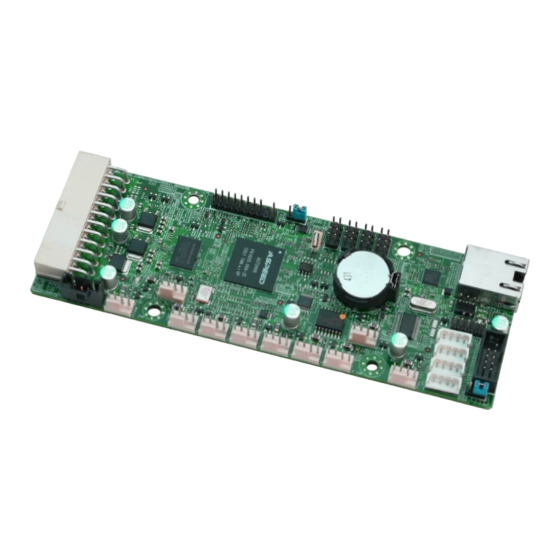
1-2:SAS3 2-3:SAS2_847D NMI X PWR LED X NIC1 X OH/FF X RST ON PWR ON Figure 2-1: Components and Connectors on the CSE-PTJBOD-CB3 Components and Connectors 6. IPMI LAN Connector: J8 1. BMC Chip 7. SC847D SAS2 I C Connectors: 2. -
Page 10: 2-2 Component And Connector Definitions
CSE-PTJBOD-CB3 Power Board User's Guide 2-2 Component and Connector Definitions 1. BMC Chip The Baseboard Management Controller (BMC) chip monitors the physical state of a system and provides communication with the system administrator through an inde- pendent connection. 2. SAS2/SAS3 I C Connectors... - Page 11 Chapter 2 Components, Connectors, Jumpers and LEDs 6. IPMI LAN Connector The Intelligent Platform Management Inter- face (IPMI) LAN connector is designated J8 and supports connectivity with a local network using cable CBL-NTWK-0584 or CBL-NTWK-0587. 7. SC847D SAS2 I2C Connectors The backplane connectors are designated J4-J7 and allow the power board to be con- nected to up to four SC847D expanders.
-
Page 12: Connectors Jumpers And Led Indicators
NMI X PWR LED X NIC1 X OH/FF X RST ON PWR ON SC847D: Use J4-J7 Figure 2-2: CSE-PTJBOD-CB3 Connectors and Jumpers Front SAS2/SAS3 and SC847D Jumpers Jumper Description Pins 1-2: IPMI factory mode, IP 192.168.1.99 Pins 2-3: User mode (static/DHCP) - Page 13 FAN9 JPW1 1-2:SAS3 2-3:SAS2_847D NMI X PWR LED X NIC1 X OH/FF X RST ON PWR ON Figure 2-3: CSE-PTJBOD-CB3 LED Indicators LED Indicators Description Heartbeat LED: A blinking LED indicates BMC activity Power LED: DC power indicator Arrow.com. Arrow.com.
- Page 14 CSE-PTJBOD-CB3 Power Board User's Guide Notes Arrow.com. Arrow.com. Arrow.com. Arrow.com. Arrow.com. Arrow.com. Arrow.com. Arrow.com. Arrow.com. Arrow.com. Arrow.com. Arrow.com. Arrow.com. Arrow.com. Downloaded from Downloaded from Downloaded from Downloaded from Downloaded from Downloaded from Downloaded from Downloaded from Downloaded from Downloaded from...
-
Page 15: Chapter 3 Connecting To The Front And Rear Backplanes
Chapter 3 Connecting to the Front and Rear Backplanes SC847D JBOD Cabling E16 I C Cabling Use the following diagram to connect the CSE-PTJBOD-CB3 to the front and rear backplanes in SC847D JBOD E16 model chassis. Jumper Settings Jumper Setting... -
Page 16: E26 I 2 C Cabling
CSE-PTJBOD-CB3 Power Board User's Guide E26 I C Cabling Use the following diagram to connect the CSE-PTJBOD-CB3 to the front and rear backplanes in SC847D-JBOD-E26 model chassis. Front Secondary Expander Front Primary Expander BPN-EXP-847DF3EL1 BPN-EXP-847DF3EL1 CBL-0157L CBL-0157L-01 CBL-0157L-01 CBL-0157L-01 CSE-PTJBOD-CB3... - Page 17 Chapter 3 Connecting to the Front and Rear Backplanes SC847 JBOD Cabling SAS3 I C Cabling in the SC847 JBOD Chassis Use the diagram below to connect the CSE-PTJBOD-CB3 to the front and rear backplanes in the SC847 JBOD chassis. Jumper Settings Jumper Setting...
- Page 18 Pins 2-3: SAS2 and SC847D setting When enabling SAS2/SAS3 functionality, use the connectors on the upper left of the CSE-PTJBOD-CB3 power board (See Page 2-4) and set the JP5 jumper as shown in the chart above. When an SC847D chassis is being used, use the connectors along the bottom edge fo the power board (See Page 2-4) and set the JP5 jumper as shown in the chart above.
-
Page 19: Sc417B Cabling
Pins 2-3: SAS2 and SC847D setting When enabling SAS2/SAS3 functionality, use the connectors on the upper left of the CSE-PTJBOD-CB3 power board (See Page 2-4) and set the JP5 jumper as shown in the chart above. When an SC847D chassis is being used, use the connectors along the bottom edge fo the power board (See Page 2-4) and set the JP5 jumper as shown in the chart above. - Page 20 CSE-PTJBOD-CB3 Power Board User's Guide Notes Arrow.com. Arrow.com. Arrow.com. Arrow.com. Arrow.com. Arrow.com. Arrow.com. Arrow.com. Arrow.com. Arrow.com. Arrow.com. Arrow.com. Arrow.com. Arrow.com. Arrow.com. Arrow.com. Arrow.com. Arrow.com. Arrow.com. Arrow.com. Downloaded from Downloaded from Downloaded from Downloaded from Downloaded from Downloaded from Downloaded from...
-
Page 21: Chapter 4 System Details
Chapter 4 System Details Chapter Overview This chapter provides information on system components which are directly affected by the CSE-PTJBOD-CB3 power board. Topics covered are the control panel, power up and power down sequences and IPMI. Control Panel Control Panel Buttons There are two push-buttons located on the left handle of the chassis. -
Page 22: Control Panel Leds
CSE-PTJBOD-CB3 Power Board User's Guide Control Panel LEDs The control panel is located on the left handle of the SC847DJ chassis and has five LEDs. These LEDs provide you with critical information related to different parts of the system. This section explains what each LED indicates when illuminated and any corrective action you may need to take. - Page 23 Chapter 4 System Component Details Power Failure: When this LED flashes, it indicates a failure in the redundant power supply. Arrow.com. Arrow.com. Arrow.com. Arrow.com. Arrow.com. Arrow.com. Arrow.com. Arrow.com. Arrow.com. Arrow.com. Arrow.com. Arrow.com. Arrow.com. Arrow.com. Arrow.com. Arrow.com. Arrow.com. Arrow.com. Arrow.com. Arrow.com. Arrow.com. Arrow.com. Arrow.com. Downloaded from Downloaded from Downloaded from Downloaded from Downloaded from Downloaded from Downloaded from...
-
Page 24: Power Up/Power Down Sequences
3. Press the power button once* 4. The CSE-PTJBOD-CB3 will initiate the power up sequence in three seconds * If the CSE-PTJBOD-CB3 already has power, the user may power up the chassis without waiting for the Blue UID LED After Normal Shutdown by IPMI or Power Button 1. -
Page 25: Cse-Ptjbod-Cb3 Ipmi Static Ip To Dhcp Setting
11. Go to the utility folder and type in: findit 00-25-90-xx-xx-xx yy.zz.255.255 Where: xx-xx-xx is, enter the CSE-PTJBOD-CB3 MAC ID. yy.zz represents the first two octets of your host IP. Example: findit 00-25-90-xx-xx-xx 10.1.255.255 12. The utility will return the IP address of the CSE-PTJBOD-CB3. Enter the IP in browser and access the IPMI web GUI Arrow.com. Arrow.com. Arrow.com. - Page 26 CSE-PTJBOD-CB3 Power Board User's Guide Notes Disclaimer (cont.) The products sold by Supermicro are not intended for and will not be used in life sup- port systems, medical equipment, nuclear facilities or systems, aircraft, aircraft devices, aircraft/emergency communication devices or other critical systems whose failure to per- form be reasonably expected to result in significant injury or loss of life or catastrophic property damage.
Need help?
Do you have a question about the CSE-PTJBOD-CB3 and is the answer not in the manual?
Questions and answers