Dormakaba ES 250 PRO Mounting Instructions
Hide thumbs
Also See for ES 250 PRO:
- Mounting instruction (68 pages) ,
- Mounting instructions (52 pages) ,
- Operating instructions manual (20 pages)

Related Manuals for Dormakaba ES 250 PRO


Summary of Contents for Dormakaba ES 250 PRO
- Page 1 ES 250 PRO/ES 250 PRO FST ES 400 PRO/ES 400 PRO FST Mounting instructions Original document 0059677-45532/17533 – 11/2023...
-
Page 2: Table Of Contents
Mounting instructions ES 250 PRO/ES 250 PRO FST ES 400 PRO/ES 400 PRO FST Contents About this document Contents and purpose Target group Other applicable documents Documents storage Abbreviations Symbols used Safety Intended use Improper use Reasonably foreseeable misuse Risk assessment... - Page 3 Mounting instructions ES 250 PRO/ES 250 PRO FST ES 400 PRO/ES 400 PRO FST 4.22 Prepare the internal cover 4.23 Mount the internal cover 4.24 Mount and connect the accessories 4.25 Position the sensors CAN BUS system CAN BUS components Properties of CAN BUS systems Structure of a CAN BUS system...
-
Page 4: About This Document
Mounting instructions ES 250 PRO/ES 250 PRO FST ES 400 PRO/ES 400 PRO FST About this document Contents and purpose The purpose of this manual is the safe and efficient mounting and commissioning of the ES PROLINE sliding door operators (hereinafter also called “operator”). -
Page 5: Symbols Used
Mounting instructions ES 250 PRO/ES 250 PRO FST ES 400 PRO/ES 400 PRO FST Parts: EM I/O Input/Output extension module EM BAS Operating mode switch extension module EM SIAK Safety and activation extension module Communication interface Symbols used 1.6.1 Hazard categories WARNING This signal word indicates a possible hazardous situation that may result in death or serious injury if not averted. -
Page 6: Safety
Mounting instructions ES 250 PRO/ES 250 PRO FST ES 400 PRO/ES 400 PRO FST Safety Intended use ES PROLINE sliding door operators are suitable for use in dry environments. The escape route variant is suitable for use on escape and emergency routes. -
Page 7: Product Description
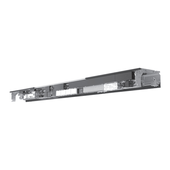
Mounting instructions ES 250 PRO/ES 250 PRO FST ES 400 PRO/ES 400 PRO FST Product description Overview Fig. 1 (1) Carriers (16) Extension module (2) Engaging unit (17) CIN (option) (3) Operator profile (18) Cable duct (4) Battery (19) Hinge profile... -
Page 8: Operating Elements
Mounting instructions ES 250 PRO/ES 250 PRO FST ES 400 PRO/ES 400 PRO FST Operating elements The control unit has a user interface with 4 keys and a 2-digit display. Fig. 2 The following functions can be executed by pressing the keys:... -
Page 9: Parts Included
Mounting instructions ES 250 PRO/ES 250 PRO FST ES 400 PRO/ES 400 PRO FST Parts included The parts included are stated on the delivery note. Fixing materials such as dowels and screws are not included. Technical data Connection voltage: 230 V 50 Hz +10%/-15%... -
Page 10: Mounting
Mounting instructions ES 250 PRO/ES 250 PRO FST ES 400 PRO/ES 400 PRO FST Mounting This manual describes the mounting of a 2-leaf unit. The same procedure should be carried out for a 1-leaf unit. Safety during mounting WARNING Danger of injury from falling objects! Falling parts or tools can cause injury. -
Page 11: Mounting The Operator
Mounting instructions ES 250 PRO/ES 250 PRO FST ES 400 PRO/ES 400 PRO FST 4.2.2 Requirements for the on-site electrical installation WARNING Danger of death due to electric current! Touching live parts will result in death or serious injury from electric shock. - Page 12 Mounting instructions ES 250 PRO/ES 250 PRO FST ES 400 PRO/ES 400 PRO FST 2-leaf unit 1-leaf, left-opening unit Fig. 4 (1) Center of the guide pulley (2) Main closing edge (3) DRIVE UNIT (4) Center of the operator wheel OL Operator length CW Clear width Fig. 3...
- Page 13 Mounting instructions ES 250 PRO/ES 250 PRO FST ES 400 PRO/ES 400 PRO FST 1-leaf, right-opening unit Fig. 5 (1) Center of the guide pulley (2) Main closing edge (3) DRIVE UNIT (4) Center of the operator wheel OL Operator length...
- Page 14 Mounting instructions ES 250 PRO/ES 250 PRO FST ES 400 PRO/ES 400 PRO FST 4.3.2 Prepare the operator profile Push the attachment strip for the DRIVE UNIT into the slot in the operator profile from the right. Fig. 6 Screw the enclosed washer and nut onto the middle threaded bolt.
- Page 15 Mounting instructions ES 250 PRO/ES 250 PRO FST ES 400 PRO/ES 400 PRO FST Push the attachment strip for the deflection device into the slot in the operator profile from the left. Fig. 8 Remove the adhesive strip protector from the rubber strip.
- Page 16 Mounting instructions ES 250 PRO/ES 250 PRO FST ES 400 PRO/ES 400 PRO FST Push both end stops onto the track profile from the outside and tighten them slightly. Fig. 11 10. Attach the clip to the center of the track profile (2-leaf units only).
- Page 17 Mounting instructions ES 250 PRO/ES 250 PRO FST ES 400 PRO/ES 400 PRO FST 4.3.3 Mount the operator profile on the wall Determine the highest point of the floor in the leaves’ area of travel. Note Use a leveling device.
- Page 18 Mounting instructions ES 250 PRO/ES 250 PRO FST ES 400 PRO/ES 400 PRO FST Position the mounting plate centrally above the passage and mark the drill holes. Fig. 15 WARNING Risk of injury due to incorrect fixing materials! If unsuitable fixing materials are used, there is a risk that parts may tear out.
- Page 19 Mounting instructions ES 250 PRO/ES 250 PRO FST ES 400 PRO/ES 400 PRO FST Hook in the drive profile. Fig. 17 Use the thread-forming screws provided to screw the operator profile to the mounting plate. To prevent noise during operation, screw the operator profile through all slots.
- Page 20 Mounting instructions ES 250 PRO/ES 250 PRO FST ES 400 PRO/ES 400 PRO FST 4.3.4 Mount the operator profile in the passage Determine the highest point of the floor in the leaves’ area of travel. Note Use a leveling device.
- Page 21 Mounting instructions ES 250 PRO/ES 250 PRO FST ES 400 PRO/ES 400 PRO FST WARNING Risk of injury due to incorrect fixing materials! If unsuitable fixing materials are used, there is a risk that parts may tear out. • Use dowels and screws that are suitable for the existing structure and the weight of the door unit.
- Page 22 Mounting instructions ES 250 PRO/ES 250 PRO FST ES 400 PRO/ES 400 PRO FST Hook the LM girder into the wall brackets. The required distance of the LM girder from the wall can be found in the manual for the relevant profile system.
- Page 23 Mounting instructions ES 250 PRO/ES 250 PRO FST ES 400 PRO/ES 400 PRO FST Hook in the drive profile. Fig. 26 12. Align the operator profile centrally between the wall mountings. Fig. 27 13. Use the cylinder head screws provided to screw the operator profile onto the LM girder.
-
Page 24: Mount The Optional Side Panels
Mounting instructions ES 250 PRO/ES 250 PRO FST ES 400 PRO/ES 400 PRO FST Mount the optional side panels Mount the wall connection profiles and the side panels according to the profile system manual. Mount the optional anti-static brushes Screw 1 anti-static brush onto each of the carriers. -
Page 25: Mount The Carriers
Mounting instructions ES 250 PRO/ES 250 PRO FST ES 400 PRO/ES 400 PRO FST Mount the carriers Mount the carriers on the door leaves according to the profile system manual. Fig. 30 Hook in the door leaf WARNING Risk of injury from heavy parts! Lifting heavy parts can lead to injury. -
Page 26: Mount The Floor Guides
Mounting instructions ES 250 PRO/ES 250 PRO FST ES 400 PRO/ES 400 PRO FST Guide the door leaves with the carriers above the track rail into the operator profile. Fig. 32 Swivel the door leaves under the operator. Place the track rollers on the track profile. -
Page 27: Align The Door Leaves
Mounting instructions ES 250 PRO/ES 250 PRO FST ES 400 PRO/ES 400 PRO FST Align the door leaves Loosen the screws on the adjustable brackets. Fig. 34 Align the door leaves by turning the adjusting screws so that the distance between the door leaves and the floor is 6 mm, and when the door is closed the center seals are parallel. - Page 28 Mounting instructions ES 250 PRO/ES 250 PRO FST ES 400 PRO/ES 400 PRO FST Tighten the adjustable brackets on the carrier. Fig. 36 Loosen the screws on the adjustable brackets. Fig. 37 WN 059677 45532 - 11/2023...
- Page 29 Mounting instructions ES 250 PRO/ES 250 PRO FST ES 400 PRO/ES 400 PRO FST Position the door leaves so that they are aligned and the distance between door leaf and wall/side panel is a maximum of 8 mm. Fig. 38 Screw the adjustable brackets tightly to the door leaf.
-
Page 30: Adjust The Opening Width
Mounting instructions ES 250 PRO/ES 250 PRO FST ES 400 PRO/ES 400 PRO FST 4.10 Adjust the opening width Slide the door leaves to the full opening width. Push the end stops onto the carriers. Fig. 40 Tighten the end stops to 4 Nm. - Page 31 Mounting instructions ES 250 PRO/ES 250 PRO FST ES 400 PRO/ES 400 PRO FST 4.11.2 On 1-leaf, left-opening units Screw the toothed belt engaging unit onto the carrier. Fig. 42 4.11.3 On 1-leaf, left-opening units if space is required for a protective panel or manual release Screw the toothed belt engaging unit onto the carrier.
-
Page 32: Mount The Optional Locking Device
Mounting instructions ES 250 PRO/ES 250 PRO FST ES 400 PRO/ES 400 PRO FST 4.11.4 On 1-leaf, right-opening units Screw the toothed belt engaging unit onto the carrier. Fig. 44 4.12 Mount the optional locking device Mount the locking device according to the accompanying manual. - Page 33 Mounting instructions ES 250 PRO/ES 250 PRO FST ES 400 PRO/ES 400 PRO FST Place the DRIVE UNIT on the threaded bolts on the attachment strip. Fig. 47 Tighten the DRIVE UNIT with the nuts and the hammerhead screw. Do not screw the rightmost nut onto the bolt yet.
-
Page 34: Mount The Tensioning Device
Mounting instructions ES 250 PRO/ES 250 PRO FST ES 400 PRO/ES 400 PRO FST 4.14 Mount the tensioning device Place the tensioning device on the threaded bolts on the attachment strip. Fig. 49 Loosely screw the nuts and washer onto the bolts. -
Page 35: Mount The Toothed Belt
Mounting instructions ES 250 PRO/ES 250 PRO FST ES 400 PRO/ES 400 PRO FST 4.16 Mount the toothed belt Remove the caps from the toothed belt engaging units. Fig. 51 Place the toothed belt around the operator wheel on the DRIVE UNIT and the guide pulley on the tensioning device. - Page 36 Mounting instructions ES 250 PRO/ES 250 PRO FST ES 400 PRO/ES 400 PRO FST Put the cap on. Fig. 54 Press the tensioning device firmly outward in order to pre-tension the toothed belt. Fig. 55 Align the tensioning device parallel to the operator profile.
- Page 37 Mounting instructions ES 250 PRO/ES 250 PRO FST ES 400 PRO/ES 400 PRO FST Insert the toothed belt into the lower toothed belt engaging unit. Fig. 58 10. Put the cap on. Fig. 59 Loosen the screws on the tensioning device. Fig. 60 12.
-
Page 38: Adjust The Tensioning Device
Mounting instructions ES 250 PRO/ES 250 PRO FST ES 400 PRO/ES 400 PRO FST 13. Tighten the screws on the tensioning device. Fig. 62 4.17 Adjust the tensioning device Slide the door leaf along the entire travel path. Check whether the toothed belt is running centrally on the wheel assembly of the tensioning device. -
Page 39: Position The Main Closing Edge
Mounting instructions ES 250 PRO/ES 250 PRO FST ES 400 PRO/ES 400 PRO FST 4.18 Position the main closing edge Loosen the screws on the toothed belt engaging units. Fig. 64 Position the main closing edge in the middle of the opening width. -
Page 40: 4.20 Mount The Cable Ducts
Mounting instructions ES 250 PRO/ES 250 PRO FST ES 400 PRO/ES 400 PRO FST 4.20 Mount the cable ducts Clip the cable ducts into the operator profile from below. Fig. 65 4.21 Mount the cover holders Mount 1 cover holder on both ends and in the middle of the operator profile. -
Page 41: Prepare The Internal Cover
Mounting instructions ES 250 PRO/ES 250 PRO FST ES 400 PRO/ES 400 PRO FST 4.22 Prepare the internal cover Slide the square nut into the groove. Fig. 67 Attention Do not mount the protective conductor in the area of movement! Screw the protective conductor into the internal cover at the desired place. -
Page 42: Mount The Internal Cover
Mounting instructions ES 250 PRO/ES 250 PRO FST ES 400 PRO/ES 400 PRO FST If the distance between the outer holder and the outer edge of the cladding is more than 80 mm, an additional piece of the hinge profile must be cut to length and mounted. - Page 43 Mounting instructions ES 250 PRO/ES 250 PRO FST ES 400 PRO/ES 400 PRO FST Open the internal cover, always holding the center of the cladding. Slide the holders for the internal cover so they match the position of the cover holders.
- Page 44 Mounting instructions ES 250 PRO/ES 250 PRO FST ES 400 PRO/ES 400 PRO FST Depending on the position of the supports, several opening angles are possible. Fig. 74 WN 059677 45532 - 11/2023...
-
Page 45: Mount And Connect The Accessories
Mounting instructions ES 250 PRO/ES 250 PRO FST ES 400 PRO/ES 400 PRO FST Attention Do not mount the protective conductor in the area of movement! Mount the protective conductor in the operator profile. Fig. 75 4.24 Mount and connect the accessories... -
Page 46: Position The Sensors
Mounting instructions ES 250 PRO/ES 250 PRO FST ES 400 PRO/ES 400 PRO FST Note The emergency stop button does not work on FST doors. Note A battery must be installed in FST doors. The battery pack only reaches its full capacity after 12 hours of charging time. The battery pack must be fully charged to ensure emergency operation. - Page 47 Mounting instructions ES 250 PRO/ES 250 PRO FST ES 400 PRO/ES 400 PRO FST The size of the detection field depends on the mounting height and the settings of the sensor (see sensor manual). According to EN 16005, the test piece CA must be detected anywhere in the sliding door’s passage area.
-
Page 48: Can Bus System
Mounting instructions ES 250 PRO/ES 250 PRO FST ES 400 PRO/ES 400 PRO FST CAN BUS system CAN BUS components Articles Article number Max. number/system FST/Standard EPS CAN 44 x 50 mm 16712401150 EPS CAN 55 x 55 mm 16712501150 CAN key switch... -
Page 49: Properties Of Can Bus Systems
Mounting instructions ES 250 PRO/ES 250 PRO FST ES 400 PRO/ES 400 PRO FST Properties of CAN BUS systems • The CAN BUS is a 4-wire bus, comprising + 24 V, GND and 2 data cables (CAN-L and CAN-H). • Because the connectors on the CAN BUS cables are very small, a housing is sometimes mounted on the connectors. - Page 50 Mounting instructions ES 250 PRO/ES 250 PRO FST ES 400 PRO/ES 400 PRO FST 5.2.1 CAN BUS Y-adapter • A CAN BUS Y-adapter is used to install branches in a CAN BUS system. • Only 1 CAN BUS component may be connected to a branch.
- Page 51 Mounting instructions ES 250 PRO/ES 250 PRO FST ES 400 PRO/ES 400 PRO FST 5.2.3 Terminating resistors • A CAN BUS system always requires 2 terminating resistors. • The 2 CAN BUS components furthest away from the control unit, measured by cable length, are fitted with the terminating resistors.
-
Page 52: Structure Of A Can Bus System
Mounting instructions ES 250 PRO/ES 250 PRO FST ES 400 PRO/ES 400 PRO FST 5.2.4 DIP switches on the sensors Warning For escape route sliding doors, a combination detector must always be connected to the inside of the MCE with the DIP switch position MCE inside 1! - Page 53 Mounting instructions ES 250 PRO/ES 250 PRO FST ES 400 PRO/ES 400 PRO FST 5.3.1 Schematic examples of wiring max. 30 m Fig. 84 max. 30 m Fig. 85 max. 30 m The terminating resistor is permanently installed in the multipoint locking system.
-
Page 54: Terminal Layout
Mounting instructions ES 250 PRO/ES 250 PRO FST ES 400 PRO/ES 400 PRO FST Terminal layout Terminal layout of the control board Fig. 87 (1) Operator locking device connection (6) Power supply connection (2) RS232 connection (7) Battery pack connection (3) Multiport Fig. 88... - Page 55 Mounting instructions ES 250 PRO/ES 250 PRO FST ES 400 PRO/ES 400 PRO FST 6.2.1 Multiport default settings The keys on the control unit can be used to select one of the following configurations (Parameter “FF”). Configuration Multiport Function Input activation level...
- Page 56 Mounting instructions ES 250 PRO/ES 250 PRO FST ES 400 PRO/ES 400 PRO FST 6.2.3 Connection on the multiports Connection for “Door closed” message For multiport default setting potential-free “Standard” 24 V DC doorbell connection Potential-free relay 24 V DC contact Item no.: 16732401150 io1 io2 io3 io4 Fig. 89...
-
Page 57: Connection As An Interlock
Mounting instructions ES 250 PRO/ES 250 PRO FST ES 400 PRO/ES 400 PRO FST Connection as an interlock 6.3.1 Standard interlock The standard interlock can be set up as a 2- or 3-way interlock. The inputs and outputs must be configured as follows for 2-way and 3-way interlocks: •... - Page 58 Mounting instructions ES 250 PRO/ES 250 PRO FST ES 400 PRO/ES 400 PRO FST 6.3.2 Time interlock The inputs and outputs must be configured as follows for 2-way and 3-way interlocks: • Input 1 (Terminal 11): Interlock pulse forwarding - Input •...
-
Page 59: Commissioning
Mounting instructions ES 250 PRO/ES 250 PRO FST ES 400 PRO/ES 400 PRO FST Commissioning Requirements • The operator is mounted correctly, mechanically and electrically. • The area of movement of the door leaf is free from obstacles. • The door is in the half-open position •... - Page 60 Mounting instructions ES 250 PRO/ES 250 PRO FST ES 400 PRO/ES 400 PRO FST 7.3.1 Service Mode In Service Mode 1, the sensors are not evaluated by the control unit. In Service Mode 2, the CAN components are not evaluated by the control unit.
- Page 61 Mounting instructions ES 250 PRO/ES 250 PRO FST ES 400 PRO/ES 400 PRO FST Display Press to exit the parameters menu. ‣ The small, spinning “o” and the “O” show that a teach-in run is required. Press for 3 seconds. ‣...
-
Page 62: Interlock Mode
Mounting instructions ES 250 PRO/ES 250 PRO FST ES 400 PRO/ES 400 PRO FST Interlock mode The activation of an interlock mode automatically changes the configuration of the EW I/O to a corresponding interlock preset. An interlock participant must be parameterized as a master. -
Page 63: Time Interlock Via Ew I/O
Mounting instructions ES 250 PRO/ES 250 PRO FST ES 400 PRO/ES 400 PRO FST Time interlock via EW I/O If one of the two doors receives an opening impulse, it opens and the other door is locked. When the set interlock time (impulse forwarding time) has elapsed, the 2nd door is unlocked and the 2nd door is opened automatically. -
Page 64: Functional Parameterization Sticker
Mounting instructions ES 250 PRO/ES 250 PRO FST ES 400 PRO/ES 400 PRO FST Functional parameterization sticker Label the functional parameterization sticker. H L NC KS short L: MP1: MP2: KS long L: MP3: KS short R: MP4 (NB): KS long R:... -
Page 65: Fire Protection Function
Mounting instructions ES 250 PRO/ES 250 PRO FST ES 400 PRO/ES 400 PRO FST Fire protection function The fire protection function enables the sliding door to close safely in case of fire. The function is controlled externally, e.g. via fire alarm systems or building management systems. -
Page 66: Parameterization
Mounting instructions ES 250 PRO/ES 250 PRO FST ES 400 PRO/ES 400 PRO FST Parameterization After carrying out a teach-in run, the operator can be operated with the basic parameters. The system offers the option to adapt the travel parameters to the actual conditions as well as to activate advanced functions. - Page 67 Mounting instructions ES 250 PRO/ES 250 PRO FST ES 400 PRO/ES 400 PRO FST WN 059677 45532 - 11/2023...
- Page 68 Mounting instructions ES 250 PRO/ES 250 PRO FST ES 400 PRO/ES 400 PRO FST WN 059677 45532 - 11/2023...
- Page 69 Mounting instructions ES 250 PRO/ES 250 PRO FST ES 400 PRO/ES 400 PRO FST WN 059677 45532 - 11/2023...
- Page 70 Mounting instructions ES 250 PRO/ES 250 PRO FST ES 400 PRO/ES 400 PRO FST WN 059677 45532 - 11/2023...
-
Page 71: Information And Error Display
Mounting instructions ES 250 PRO/ES 250 PRO FST ES 400 PRO/ES 400 PRO FST WN 059677 45532 - 11/2023... - Page 72 Mounting instructions ES 250 PRO/ES 250 PRO FST ES 400 PRO/ES 400 PRO FST WN 059677 45532 - 11/2023...
- Page 73 Mounting instructions ES 250 PRO/ES 250 PRO FST ES 400 PRO/ES 400 PRO FST WN 059677 45532 - 11/2023...
- Page 74 Mounting instructions ES 250 PRO/ES 250 PRO FST ES 400 PRO/ES 400 PRO FST WN 059677 45532 - 11/2023...
- Page 75 Mounting instructions ES 250 PRO/ES 250 PRO FST ES 400 PRO/ES 400 PRO FST WN 059677 45532 - 11/2023...
- Page 76 Mounting instructions ES 250 PRO/ES 250 PRO FST ES 400 PRO/ES 400 PRO FST WN 059677 45532 - 11/2023...
- Page 77 Mounting instructions ES 250 PRO/ES 250 PRO FST ES 400 PRO/ES 400 PRO FST WN 059677 45532 - 11/2023...
-
Page 78: Replace The Battery
Mounting instructions ES 250 PRO/ES 250 PRO FST ES 400 PRO/ES 400 PRO FST Perform network reset Switch off the power supply Remove the battery (if present) Connect the battery (if present) Switch on the power supply Replace the battery... - Page 79 Mounting instructions ES 250 PRO/ES 250 PRO FST ES 400 PRO/ES 400 PRO FST WN 059677 45532 - 11/2023...
- Page 80 Copyright dormakaba 2023 © dormakaba Deutschland GmbH DORMA Platz 1 58256 Ennepetal Germany +49 2333 793-0 www.dormakaba.com www.dormakaba.com...
Need help?
Do you have a question about the ES 250 PRO and is the answer not in the manual?
Questions and answers