
Related Manuals for Hukseflux SR300-D1


Summary of Contents for Hukseflux SR300-D1
- Page 1 Hukseflux Thermal Sensors USER MANUAL SR300-D1 | SR200-D1 | SR100-D1 Industrial pyranometers Copyright by Hukseflux | manual v2416 | www.hukseflux.com | info@hukseflux.com...
-
Page 2: Cautionary Statements
Failure to comply with a caution statement may lead to minor or moderate physical injuries. NOTICE Failure to comply with a notice may lead to damage to equipment or may compromise reliable operation of the instrument. SR300-D1 SR200-D1 SR100-D1 manual v2416 2 /105... -
Page 3: Table Of Contents
Electrical installation design Electrical connections Setting up Modbus RTU communication Programming, register structure Instrument diagnostics Instrument diagnostics for different sensor models On-site diagnostics: status LED (SR300-D1 only) Remote diagnostics Maintenance and trouble shooting SR300-D1 SR200-D1 SR100-D1 manual v2416 3 /105... - Page 4 Recommended maintenance and quality assurance Trouble shooting Calibration and validation Spare parts Repair services SR300-D1, SR200-D1 and SR100-D1 The SR300-D1 ventilator Scratches on domes; optical surface imperfections Appendices Appendix on standards for classification and calibration Appendix on calibration hierarchy Appendix on expected change of the WRR scale...
-
Page 5: List Of Symbols
Baseline Surface Radiation Network Lightning Protection Zone Surge Protection Device American Wire Gauge MTBF Mean Time Between Failures ® Modbus is a registered trademark of Schneider Electric, licensed to the Modbus Organization, Inc. SR300-D1 SR200-D1 SR100-D1 manual v2416 5 /105... -
Page 6: Introduction
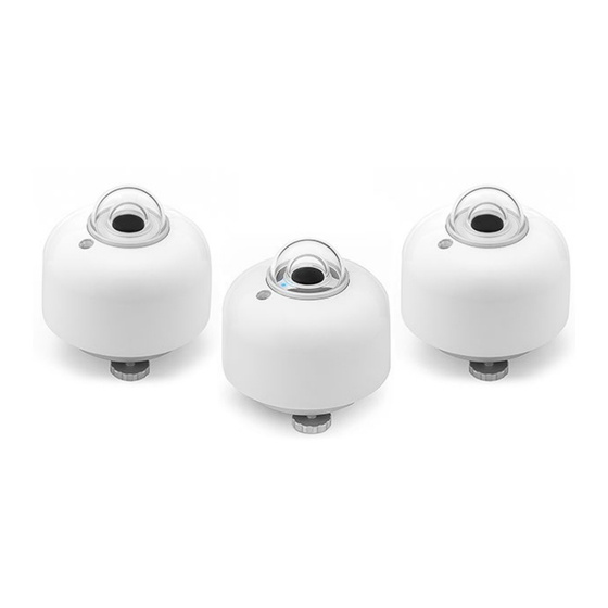
Figure 0.1 Industrial pyranometer models SR300-D1, SR200-D1 and SR100-D1. In front the leading Class A model SR300-D1, with heating, tilt sensor and the blue status LED. Left and right the non-heated Class A model SR200-D1 and Class B model SR100-D1. - Page 7 They offer a digital output via Modbus RTU over 2-wire RS-485. SR300-D1’s dome is heated by actively circulating air between the sensor’s inner and outer domes.
- Page 8 Figure 0.2 SR300-D1 includes a digital tilt angle measurement, a practical feature for remote verification of instrument mounting orientation. The above image depicts two SR300- D1 pyranometers, one tilted for Plane of Array (POA) measurement, and another mounted horizontally for Global Horizontal Irradiance (GHI) measurement.
- Page 9 Immunity to voltages and currents - surges Hukseflux industrial pyranometers are tested and classified for Industrial Environments according to IEC 61326-1 and IEC 61000-6-2. When designing a measuring system, pyranometer users may reach several levels of immunity. To attain the required level of...
- Page 10 EU and US safety regulations. SR300-D1: heated for high data availability, operation in 3 power modes SR300-D1 includes internal heating. Heating mitigates dew and frost, which leads to high data availability. Heating is achieved by actively circulating air between the sensor’s inner and outer domes.
- Page 11 Plane pyranometer (front). of Array (POA). Heater and ventilation may be remotely switched on and off. The SR300-D1 has 3 power modes: Normal power mode. In this mode, the instrument is heated and ventilated for •...
- Page 12 For PV systems with single-axis trackers, IEC 61724-1 Class A performance monitoring systems also require a tilt angle measurement of the tracker. This is done by mounting SR300-D1 attached to the module frame. Every SR300-D1 accelerometer is individually calibrated and temperature compensated between (-30 and +50) ˚C, resulting in a high measurement accuracy of <...
- Page 13 Optional accessories for mounting and levelling There are several mounting options available for SR300-D1, SR200-D1 and SR100-D1: the most common ones are a levelling mount and a tube levelling mount. They allow for simplified mounting, levelling and instrument exchange on either a flat surface or a tube.
- Page 14 Figure 0.9 LM01 levelling mount is the most popular option for pyranometers: practical spring-loaded mount for easy mounting, levelling and instrument exchange on flat surfaces. The spring-loaded mounting has the advantage that levelling can be done quickly, without unlocking the instrument. SR300-D1 SR200-D1 SR100-D1 manual v2416 14 /105...
-
Page 15: Ordering And Checking At Delivery
The order code consists of the instrument model optionally followed by the model for mounting brackets, optionally followed by a code for a cable. E.g. to order an SR300-D1 with TLMB01 mounting bracket and 3 m cable the order code would be SR300-D1-TLMB01-03. -
Page 16: Included Items
The instrument irradiance output should go down and within one minute approach 0 W/m 3. Remove the sun screen, inspect the bubble level. For SR300-D1 compare to the tilt angle output (within 1 ° when bubble is entirely in ring). -
Page 17: Instrument Principle And Theory
1000 10000 wavelength [x 10 Figure 2.1.1 Spectral response of the pyranometer compared to the solar spectrum. The pyranometer only cuts off a negligible part of the total solar spectrum. SR300-D1 SR200-D1 SR100-D1 manual v2416 17 /105... - Page 18 The thermopile sensor generates a voltage output signal that is proportional to the solar irradiance. SR300-D1 SR200-D1 SR100-D1 manual v2416 18 /105...
-
Page 19: Iso 9060:2018 Pyranometer Classification
The effect of having a second dome results in a strong reduction of instrument unwanted thermal offsets. Modern pyranometers such as SR300-D1 often have additional features such as dew and frost mitigation to improve data availability and internal diagnostic sensors (for example for tilt, pressure and humidity) to verify that the instrument operates under the correct conditions. - Page 20 (creating a • diffusometer) with a shadow ring or shading ball, using the same instrument model you can perform uncertainty evaluations with negligible (zero) spectral errors • SR300-D1 SR200-D1 SR100-D1 manual v2416 20 /105...
-
Page 21: Specifications
3 Specifications 3.1 General overview This section provides a brief overview of the Hukseflux industrial pyranometers. INSTRUMENT PURPOSE AND INTENDED USE A pyranometer measures the solar radiation received by a plane surface from a 180 ° field of view angle. This quantity, expressed in [W/m ], is called “hemispherical”... - Page 22 Remote diagnostics measurements Instrument body ● ● ● temperature Internal humidity ● ● ● Instrument tilt ● Instrument rotation ● Internal pressure ● Heater current ● Ventilator current ● Ventilator speed ● SR300-D1 SR200-D1 SR100-D1 manual v2416 22 /105...
-
Page 23: Rated Operating Conditions
3.2 Rated operating conditions Hukseflux industrial pyranometer models are tested for a wide range of operating conditions. To avoid permanent damage to the instrument, guarantee reliable operation and measure accurately the instrument must be operated within the range of conditions listed below. -
Page 24: Pyranometer Specifications And Classification
< ± 0.2 % < ± 0.2 % < ± 0.2 % ‡ (0 to 90 ° at 1000 W/m Additional signal processing error none (signal processing errors are included in other specifications) SR300-D1 SR200-D1 SR100-D1 manual v2416 24 /105... -
Page 25: Electrical Specifications
NOTICE SR300-D1 does not comply with ISO 9060 Class A criteria when the heater is switched on while the ventilator is switched off (invalid mode). See the appendix on ISO and WMO classification tables for the comparison of the above specifications to ISO 9060. - Page 26 0.15 m, stripped ends with ferrules SR300-D1 can be operated in 3 different power modes. This allows users of SR300-D1 to save power while still making use of the advantages of SR300-D1 over the other models. For SR300-D1, performance in all valid modes complies with ISO 9060 Class A classification criteria.
- Page 27 Hukseflux industrial pyranometers are suitable for use in industrial environments such as PV power plants. The instruments meet industrial-level EMC requirements and have been designed to withstand electrical surges if the installation instructions in this document are followed and the instrument is used within the rated conditions as listed in the section about rated operating conditions.
-
Page 28: Weight And Dimensions
Hukseflux industrial pyranometers act as a Modbus RTU server that must be combined with a data acquisition system that can act as a Modbus RTU client. The server and client must be configured to have the same serial settings. DIGITAL COMMUNICATION... - Page 29 (4) outer dome (5) status LED (SR300-D1 only) (6) inner dome (7) thermal sensor with black coating (8) internal ventilation vents (SR300-D1 only) (9) quick release system of the sun screen (10) bubble level window (11) bubble level (12) instrument body...
- Page 30 Figure 3.5.2 Dimensions of Hukseflux industrial pyranometers. SR300-D1 SR200-D1 SR100-D1 manual v2416 30 /105...
-
Page 31: Optional Accessories
3.6 Optional accessories The table provides an overview of accessories that are compatible with the Hukseflux industrial pyranometers. ACCESSORIES Mounting PMF01 – pyranometer mounting fixture Pyranometer mounting fixture for 1 pyranometer, horizontal or tilted PMF02 – dual pyranometer mounting fixture... -
Page 32: Measurands, Certificates And Calibration
3.7 Measurands, certificates and calibration Hukseflux industrial pyranometers are used to measure instantaneous hemispherical solar radiation as well as statistical information such as average, min/max and standard deviation, all in [W/m ], over a certain readout interval. From the average and the readout interval, the user can also calculate time-integrated irradiance (radiant exposure) in [W∙h/m... - Page 33 Albedo (requires 2 instruments) • Sunshine duration (requires a real-time clock and • some post-processing) Input quantity instrument body temperature Instrument body temperature ± 0.5 °C measurement uncertainty Instrument body temperature resolution 7.8 x 10 °C SR300-D1 SR200-D1 SR100-D1 manual v2416 33 /105...
- Page 34 SR300-D1 includes an accelerometer that can be used to measure the instrument orientation: tilt and rotation angle. The tilt measurement can be used to detect undesired changes in orientation when the instrument is mounted in a fixed orientation or to track the orientation of the instrument when mounting the instrument on a solar tracker.
- Page 35 < 2 years Reference conditions 20 °C, normal incidence solar radiation, horizontal mounting, irradiance level 1000 W/m For SR300-D1: medium power mode i.e. heater [OFF] and ventilator [ON]. Validity of calibration Based on experience the instrument sensitivity will not change during storage. During use under exposure to solar radiation the instrument “non-stability”...
-
Page 36: Standards And Recommended Practices For Use
Methods of Observation, measuring hemispherical solar and Volume 1, Measurement of direct solar radiation Meteorological Variables, 2023 edition, chapter 7, measurement of radiation, 7.3 measurement of global and diffuse solar radiation SR300-D1 SR200-D1 SR100-D1 manual v2416 36 /105... -
Page 37: General Use For Solar Radiation Measurement
2023 edition, chapter 7, measurement of radiation, 7.3 measurement of global and diffuse solar radiation Baseline Surface Radiation Network, BSRN Operations Manual ( WMO / TD No 1274, L. J. B. McArthur, April 2005) SR300-D1 SR200-D1 SR100-D1 manual v2416 37 /105... -
Page 38: Specific Use For Pv System Performance Testing
Class C pyranometers may be used. SR300-D1 also includes an accelerometer that can be used to measure instrument tilt. For PV systems with single-axis trackers, IEC 61724-1 Class A systems also require a tilt angle measurement. - Page 39 – guidelines for measurement, data Reporting Photovoltaic Non-Concentrator exchange and analysis System Performance SR300-D1 complies with its standard configuration, with the IEC 61724-1:2021 COMMENT: confirms that a pyranometer is the requirements of Class A PV monitoring systems preferred instrument for outdoor PV testing.
-
Page 40: Specific Use In Meteorology And Climatology
Manual ( WMO / TD No 1274, L. J. B. McArthur, April 2005) In case there is no danger of dew and frost deposition, the SR300-D1 medium power mode (using the ventilator but not the heater) offers the most accurate measurements over short time intervals. - Page 41 PV modules, there is an increased demand to measure the albedo at PV power plants. This is possible with pyranometers, but there are a few things to keep in mind. A summary of Hukseflux’ recommendations for albedo measurement: Choice of instruments: use spectrally flat pyranometers.
-
Page 42: General Use For Diffuse Radiation Measurement
4.7 General use for diffuse radiation measurement With its outstanding zero offset specification and the fact that it is spectrally flat, SR300-D1 is also the instrument of choice for high-accuracy diffuse radiation measurement. 4.8 Use in residential, commercial and light-industrial... -
Page 43: Reducing Environmental Impact
Extension of the calibration interval means the user is working beyond the rated operating conditions of the instrument. The accuracy of the measurement is put at risk. The cost of recalibration, however, can be high. Hukseflux’ worldwide calibration network will help you reduce these costs. Learn more about Hukseflux... -
Page 44: Installation
5 Installation This chapter describes the installation of Hukseflux industrial pyranometers SR300-D1, SR200-D1 and SR100-D1. Aspects to be considered include: finding a suitable location for performing measurements, • mounting the instrument, • the electrical installation of the instrument including earthing and surge protection •... -
Page 45: Configuring The Instrument
In this case, connectors are preferably pointed down, in order to avoid ingress of moisture. For SR300-D1 the internal digital tilt sensor may be used for long-term, remote monitoring of the instrument orientation. For measuring ground-reflected solar irradiance or derived quantities, such as ground albedo, a pyranometer should be installed in inverted or downward facing position. - Page 46 Setting the device address and serial communication settings (BAUD rate and parity) can be done in different ways: • by connecting the sensor to a PC and using the Hukseflux Sensor Manager; by connecting the sensor to a PC and using another Modbus testing tool. There are •...
-
Page 47: Mechanical Installation Of The Instrument
5.3.1 Instrument mounting Hukseflux industrial pyranometers can be mounted using the two M5 mounting points, or the M6 mounting point in the centre, see the section about weight and dimensions for details. - Page 48 5.3.3 Installation and removal of the sun screen The quick release system of the sun screen of Hukseflux industrial pyranometers allows for easy and secure mounting and removal of the sun screen on the instrument. It is not necessary to remove the sun screen to be able to inspect the bubble level.
- Page 49 Never lift the pyranometer using the sun screen as the instrument may drop out and become damaged. NOTICE Do not lift the pyranometer using the sun screen. SR300-D1 SR200-D1 SR100-D1 manual v2416 49 /105...
- Page 50 Figure 5.3.4.1 Connection of the cable connector to the chassis connector: make sure to completely tighten the screw lock. This is necessary for proper sealing against moisture and proper electrical connection of conductors and cable shield. SR300-D1 SR200-D1 SR100-D1 manual v2416 50 /105...
- Page 51 5.3.5 Installation and removal of the dome protector Hukseflux industrial pyranometers are supplied with the DP01 dome protector to prevent damage during transport, installation and removal. To remove the dome protector, press on both sides of the dome protector and lift the dome protector of the instrument, as illustrated in the figure below.
- Page 52 5.3.6 Optional mounts Hukseflux offers a range of mounting options. See the section about optional accessories for an overview of all accessories. Consult the individual manuals of the mounting accessory for installation instructions. Figure 5.3.6.1 Overview of Hukseflux mounting options. 1. TLM01, 2. PMF02, 3. PMF01, 4.
- Page 53 If the bottom part is not accessible, the connection between SR300-D1 and the mount can be made by using a 10 mm spanner. The spanner may be used as well to lock, or unlock, when the pyranometer is already fitted to the mount.
- Page 54 Figure 5.3.6.1.2 Bottom of LM01 levelling mount. Preferred (un)locking with 4 mm hex key. Figure 5.3.6.1.3 LM01 levelling mount seen from above: (un)locking with a 10 mm spanner. Figure 5.3.6.1.4 LM01 levelling mount seen from the side: (un)locking with a 10 mm spanner. SR300-D1 SR200-D1 SR100-D1 manual v2416 54 /105...
- Page 55 5.3.6.2 Tube Levelling mount TLM01 A pyranometer may also be mounted on a tube or a mounting rod using the optional tube levelling mount. Figure 5.3.6.2.1 Pyranometer mounted with its optional tube levelling mount on a tube. SR300-D1 SR200-D1 SR100-D1 manual v2416 55 /105...
- Page 56 25 to 40 mm (tube not included). Installation requires a 4 mm hex key. Figure 5.3.6.2.2 Optional tube levelling mount; installation requires a 4 mm hex key. SR300-D1 SR200-D1 SR100-D1 manual v2416 56 /105...
-
Page 57: Electrical Installation Design
Figure 5.4.1.1: Hukseflux industrial pyranometers should be installed in LPZ2. Hukseflux SPD01 is a type 2 SPD which is used on the zone boundary from LPZ0b to LPZ2. - Page 58 SPD of the correct type should be installed as indicated in Figure 5.4.1.1. For example, the Hukseflux SPD01 is a type 2 SPD which is used on the zone boundary from LPZ0b to LPZ2. 5.4.2 Cabling and surge protection An optional cable of 3 meters long (10 ft) is supplied with the pyranometer.
- Page 59 (loss of data) or, eventually, to cause damage. Hukseflux industrial pyranometers and SPD01 should be connected to the same earth potential and the resistance between these two connections points should be minimised, but should not exceed 1 Ω...
- Page 60 WARNING Connect the earthing terminal to earth ground to guarantee personal safety. When a Hukseflux industrial pyranometer is directly connected to a SCADA system, the earthing terminal of the pyranometer should be connected to earth as well as the earth ground of the SCADA system to realise equipotential bonding.
- Page 61 5.4.5 RS-485 network Hukseflux industrial pyranometers are used in a two-wire (half-duplex) RS-485 network. In such a network the pyranometer acts as a server device and responds to data requests from the client device. An RS-485 network (or bus), consists of a wire pair for data transmission and a signal ground wire.
- Page 62 +5 VDC supply which is referenced to the signal ground and on the data[-] line to the signal ground. This will keep the data lines in a well-defined state when none of the connected devices is controlling the bus. SR300-D1 SR200-D1 SR100-D1 manual v2416 62 /105...
-
Page 63: Electrical Connections
5.5.1 Wiring and connections To use a Hukseflux industrial pyranometer, the instrument must be connected to a power supply and an RS-485 network via the M12-A connector. Table 5.3.1.1 shows the electrical connections with the insulation colours used in the cable that is part of the delivery. - Page 64 5.5.3 Connection to a PC Configuration of Hukseflux pyranometers is most easily done with the instruments connected to a PC and using the Hukseflux Sensor Manager software. This software provides a user-friendly way to connect to the instrument and to adjust the communication settings, even without knowledge of the current configuration settings using the dedicated auto-connect feature.
-
Page 65: Setting Up Modbus Rtu Communication
5.6 Setting up Modbus RTU communication Hukseflux industrial pyranometers function as Modbus RTU servers. The instruments must be used in conjunction with a client device, such as a PC or data- logger. The server device responds to requests sent by the client device. -
Page 66: Instrument Diagnostics
Read the following section to see which diagnostic features are supported by the different instrument models. For SR300-D1 the power and communication status LED provides a visual check of the instrument status. This on-site diagnostic feature can be convenient during installation or while inspecting the instrument before use or during servicing. -
Page 67: Instrument Diagnostics For Different Sensor Models
Remote diagnostics measurements Instrument body ● ● ● temperature Internal humidity ● ● ● Instrument tilt ● Instrument rotation ● Internal pressure ● Heater current ● Ventilator current ● Ventilator speed ● SR300-D1 SR200-D1 SR100-D1 manual v2416 67 /105... -
Page 68: On-Site Diagnostics: Status Led (Sr300-D1 Only)
6.2 On-site diagnostics: status LED (SR300-D1 only) The power and communication status LED can be used as a visual check by local operators to verify that the instrument is properly connected to power and communicates with a Modbus RTU client. -
Page 69: Remote Diagnostics
At night, the instrument temperature is normally lower than ambient air temperature. Infra red radiation loss from the sky causes the instrument to cool, potentially to temperatures below dewpoint. For SR300-D1 the internal heating may keep the instrument permanently above dewpoint. - Page 70 In case of condensation of droplets inside the instrument, contact the manufacturer. At the factory it is possible to replace the desiccant, and it may be possible to repair the instrument in case of leaks. SR300-D1 SR200-D1 SR100-D1 manual v2416 70 /105...
- Page 71 To allow remote monitoring of the instrument orientation and to assist in the tilted installation of the instrument, the SR300-D1 is equipped with a digital tilt sensor. The tilt measurement is actually performed by an accelerometer which measures the gravitational acceleration on three axes and calculates the corresponding zenith tilt and rotation angles of the pyranometer.
- Page 72 Disable or ignore the output in case this produces significant errors. Consult the “Hukseflux industrial pyranometer programming manual” and the instrument “register list” for more details. Figure 6.3.3.1 Illustration of the accelerometer x-, y- and z-components and the tilt and rotation angles.
- Page 73 The reference value for the leak indicator is set at the factory. Note that when the instrument is opened the reference value for the indicator needs to be reset. The procedure for resetting of the leak indicator is described in the Hukseflux Sensor Manager manual.
- Page 74 RPM and current and heater current registers can be used to further investigate the problem. Contact the manufacturer and review the data to discuss the appropriate action. 6.3.6 Internal heating (SR300-D1 only) MEASURANDS FOR DIAGNOSTICS Alert heater undercurrent flag...
- Page 75 Therefore the overall heat generation will always be larger than just that of the heater. 6.3.7 Internal ventilation (SR300-D1 only) MEASURANDS FOR DIAGNOSTICS Alert...
- Page 76 -10 °C ventilator speed may be significantly lower. When the speed consistently falls below 2000 RPM, maintenance is required, and replacement of the ventilator may be needed. See chapter 7 for details on ventilator maintenance. SR300-D1 SR200-D1 SR100-D1 manual v2416 76 /105...
-
Page 77: Maintenance And Trouble Shooting
IEC recommends weekly cleaning and inspection for its Class A systems, and yearly pyranometer re-calibration. WMO recommends daily inspection and cleaning of pyranometers used in meteorological networks. SR300-D1 SR200-D1 SR100-D1 manual v2416 77 /105... - Page 78 Inspect the dome. Check the dome for scratches or damage, see also the appendix on optical surface imperfections. Inspect the interior of the dome for condensation. Inspect mounting position, inspect levelling and tilt angle and adjust if necessary. SR300-D1 SR200-D1 SR100-D1 manual v2416 78 /105...
-
Page 79: Trouble Shooting
Desiccant replacement (< 5 year interval, typically replaced replacement during calibration, two bags of silica gel, 2 x 1 g) SR300-D1 only: Ventilator replacement (< 5 year interval) if applicable/necessary, contact our service department to arrange specific parts replacement. 7.2 Trouble shooting Table 7.2.1 Trouble shooting for industrial pyranometers (continued on next pages) - Page 80 Hukseflux Sensor Manager. Connect sensor to a PC and perform a search operation with the Sensor Manager to determine the pyranometer’s device address and serial communication settings.
- Page 81 Both can no longer be considered reliable. The factory may perform sensor diagnostics and make a quotation for repair. It may be possible to disassemble the instrument, replace parts and test and calibrate the repaired instrument. SR300-D1 SR200-D1 SR100-D1 manual v2416 81 /105...
-
Page 82: Calibration And Validation
NOTE: the calibration reference condition is “medium power mode” i.e. ventilated and not heated. NOTE: the height of SR300-D1 is different from that of SR30. Adjustments must be made to put the detectors at the same height relative to the lamp source. - Page 83 In case of field comparison, ISO 9847 recommends field validation and calibration relative to a higher class pyranometer. Hukseflux recommends to use sensors of the same model and class or better, because similar instruments will have comparable offsets. It is therefore just as good to compare to pyranometers of the same brand and type as to compare to an instrument of a higher class.
-
Page 84: Spare Parts
• sun screen • • 3 m cable for SR300-D1, with female M12-A connector at sensor end, conductors stripped over 0.15 m with ferrules levelling mount, for spring-loaded levelling and mounting on a surface • (order number LM01) tube levelling mount, for spring-loaded levelling and mounting on a tube, includes •... -
Page 85: Repair Services Sr300-D1, Sr200-D1 And Sr100-D1
Calibration includes a validation, and a certificate is issued. Certificates are also added for directional response -, temperature response - and accelerometer testing. Table 7.5.1 Required testing of SR300-D1 as a function of the most common repair services. SERVICING SR300... -
Page 86: The Sr300-D1 Ventilator
• excessive mechanical shocks and vibrations 7.7 Scratches on domes; optical surface imperfections Hukseflux has in-house test procedures to verify if surface imperfections (scratches and digs) on the pyranometer domes are permissible or not. The procedures essentially check if, with a certain scratch the pyranometer perform as required. - Page 87 NOTE 1: Class A and Class B instruments are repairable, and outer domes can be replaced. For Class C instruments, repair and replacement of domes is not economically attractive. SR300-D1 SR200-D1 SR100-D1 manual v2416 87 /105...
- Page 88 NOTE 2: in case a dome is replaced for a Class A instrument, a directional response test must be performed to verify that the instrument meets Class A directional response requirements. NOTE 3: ISO 10110 tests for surface imperfections are subjective. SR300-D1 SR200-D1 SR100-D1 manual v2416 88 /105...
-
Page 89: Appendices
(source ISO 9847:2023). WRR is maintained by the World Radiation Center in Davos Switzerland (PMOD /WRC), using a group of instruments called the World Standard Group (WSG). PMOD/WRC is a SR300-D1 SR200-D1 SR100-D1 manual v2416 89 /105... - Page 90 The Hukseflux standard is traceable to an outdoor WRR calibration. Some small corrections are made to transfer this calibration to the Hukseflux standard conditions: sun at zenith and 1000 W/m irradiance level.
-
Page 91: Appendix On Expected Change Of The Wrr Scale
WMO does not recommend to correct past data. It does, however, recommend to store information about the scale. Hukseflux in its latest industrial pyranometers allows to add metadata, to indicate if calibration is traceable to WRR or to the new scale, to calibration records and to records of calibration history. -
Page 92: Appendix On Meteorological Radiation Quantities
A pyranometer measures irradiance. The time integrated total is called radiant exposure. In solar energy, radiant exposure is often given in W∙h/m Table 8.5.1 Meteorological radiation quantities as recommended by WMO (additional symbols by Hukseflux). POA originates from ASTM and IEC standards. SYMBOL DESCRIPTION... -
Page 93: Appendix On Iso 9060:2018 And Wmo Classification Tables
Table 8.6.1 Valid classification table for pyranometers per ISO 9060:2018 and WMO. NOTE: WMO specification of spectral selectivity is different from that of ISO. Hukseflux conforms to the ISO limits. WMO also specifies expected accuracies. ISO finds this not to be a part of the classification system, because it also involves calibration. - Page 94 ISO /IEC Guide 98-4 Uncertainty of measurement — Part 4: Role of measurement uncertainty in conformity assessment. *** in ISO 9060 offsets due to rapid temperature changes by cold rain showers are excluded from zero offset b. SR300-D1 SR200-D1 SR100-D1 manual v2416 94 /105...
-
Page 95: Appendix On Iso 9060:1990 Classification No Longer Valid
ISO 9060:1990 has been superseded by ISO 9060:2018, see the earlier appendix on ISO and WMO classification tables. NOTE: WMO specification of spectral selectivity is different from that of ISO. Hukseflux conforms to the ISO limits. WMO also specifies expected accuracies. ISO finds this not to be a part of the classification system, because it also involves calibration. -
Page 96: Appendix On The Definition Of Pyranometer Specifications
WMO 7.3.2.5: Table 7.5 lists the expected maximum deviation from the true value, excluding calibration errors. ** At Hukseflux the expression ± 1 % is used instead of “a range of 2 %”. *** ISO 9060:1990 an instrument is subject to conformity testing of its specifications. Depending on the classification, conformity compliance can be proven either by group- or individual compliance. - Page 97 Hukseflux sensitive. For a normal pyranometer this should be in the (0.3 to 3) x 10 m range. Some pyranometers with coloured glass domes have a limited spectral range. SR300-D1 SR200-D1 SR100-D1 manual v2416 97 /105...
-
Page 98: Appendix On Terminology/Glossary
PV irradiance array (ref: IEC 61724, ISO TR 9901) Reflected also RHI: ground-reflected irradiance incident upon a surface, oriented Horizontal horizontally facing down. Irradiance (ref: IEC 61724, ISO TR 9901) SR300-D1 SR200-D1 SR100-D1 manual v2416 98 /105... - Page 99 + 90 °. (ASTM G113-09) Sunshine sunshine duration during a given period is defined as the sum of that sub-period duration for which the direct solar irradiance exceeds 120 W/m (ref: WMO) SR300-D1 SR200-D1 SR100-D1 manual v2416 99 /105...
-
Page 100: Appendix On Uncertainty Evaluation
3) A separate estimate has to be entered to allow for estimated uncertainty due to the instrument maintenance level. 4) The calibration uncertainty has to be entered. Note that Hukseflux calibration uncertainties are lower than those of alternative equipment. These uncertainties are entered in measurement equation (equation is usually Formula 0.1: E = U/S), either as... - Page 101 WMO states that this uncertainty may be achieved with appropriate facilities, well-trained staff and good quality control for clear days at mid-latitudes, at solar noon. The table below provides estimates of achievable uncertainties for various seasons and locations. SR300-D1 SR200-D1 SR100-D1 manual v2416 101 /105...
- Page 102 11.7 % 11.8 % 14.1 % summer equator 11.8 % 11.8 % 13.7 % spectrally flat Class C pole 13.8 % 13.8 % 16.7 % winter mid-latitude 17.4 % 17.6 % 25.1 % SR300-D1 SR200-D1 SR100-D1 manual v2416 102 /105...
-
Page 103: Eu Declaration Of Conformity
EU RoHS2 (2011/65/EU) and EU 2015/863 amendment known as RoHS3 EMC Emission EN-IEC 61326-1:2013, EN-IEC 61326-1:2021 (report 230473RPT02) EMC Immunity EN-IEC 61326-1:2013, EN-IEC 61326-1:2021, EN-IEC 61000-6-2:2019 (report 230473RPT02) Eric HOEKSEMA Director Delft, 22 May 2024 SR300-D1 SR200-D1 SR100-D1 manual v2416 103 /105... - Page 105 © 2024, Hukseflux Thermal Sensors B.V. www.hukseflux.com Hukseflux Thermal Sensors B.V. reserves the right to change specifications without notice.
Need help?
Do you have a question about the SR300-D1 and is the answer not in the manual?
Questions and answers