
Subscribe to Our Youtube Channel
Related Manuals for Hukseflux TPSYS20


Summary of Contents for Hukseflux TPSYS20
- Page 1 USER MANUAL TPSYS20 High-accuracy thermal conductivity measuring system Copyright by Hukseflux | manual v2202 | www.huksefluxusa.com info@huksefluxusa.com...
-
Page 2: Cautionary Statements
Failure to comply with a caution statement may lead to risk of minor or moderate physical injuries. NOTICE Failure to comply with a notice may lead to damage to equipment or may compromise reliable operation of the instrument. TPSYS20 manual v2202 2/75... -
Page 3: Table Of Contents
Instrument principle and theory Operating principle of thermal needle probes Measurement and Control Unit Measurement model and data analysis Specifications Specifications of TPSYS20 Dimensions of TPSYS20 Installation and connection Hardware installation Opening the graphical user interface Setting the system clock... -
Page 4: List Of Symbols
Standard uncertainty in a u(a) units of a (Relative) expanded uncertainty in a U(a)/a (Relative) standard uncertainty in a u(a)/a Coverage factor of U(a) Acronyms Graphical User Interface Keyboard Display Measurement Control Unit Personal Computer Power Supply Unit TPSYS20 manual v2202 4/75... -
Page 5: Introduction
If needed, TPSYS20 can be powered from a 12 V battery, so that it may be used in the field. TPSYS20 is operated in conjunction with a PC. An intuitive and easy-to-use graphical user interface allows the user to set measurement parameters, control measurements, view measurement progress and view and download measurement data. - Page 6 The latter reduces effect of specimen temperature drift on the measurement result. Figure 0.3 TPSYS20 is delivered with either a TP02 Non-Steady-State Probe or its smaller equivalent TP08.
- Page 7 TPSYS20 can be used to measure thermal conductivities in the range from 0.1 to 6.0 W/(m·K). Recommended specimen dimensions are a diameter of 100 mm or more and a length of at least 160 mm for TP02 (specimen volume ~1.3 L) or 80 mm for TP08...
- Page 8 FTN02, MTN02 and TNS02 systems designed for outdoor use. User interface: MCU as a web server TPSYS20 is controlled via a PC. The TPSYS20 MCU can be connected to a local area network via ethernet or directly to a PC via USB. The graphical user interface is available through a webpage and can be opened in any of the supported web browsers.
-
Page 9: Accessories
TPSYS20 is a complete measuring system delivered with either probe TP02 or TP08. Besides this option, there are several accessories. See Chapter 1 Ordering and checking at delivery for a complete overview. Accessories For high accuracy calibration dedicated CRC01 Calibration Reference Cylinders are available. -
Page 10: Ordering And Checking At Delivery
Ordering and checking at delivery Ordering TPSYS20 The standard configuration of TPSYS20 includes either a TP02 or a TP08 thermal needle probe. • TPSYS20 with TP02 probe, order code TPSYS20-02 • TPSYS20 with TP08 probe, order code TPSYS20-08 Included items Arriving at the customer, the TPSYS20 delivery should include: •... - Page 11 GT01 – a spare set of 5 guiding tubes for TP08 • GT02 – a spare set of 5 guiding tubes for TP02 Figure 1.2.2 TPSYS20 is delivered with either a TP02 or TP08 thermal needle probe. Spare probes can be ordered as an accessory. TPSYS20 manual v2202...
-
Page 12: Instrument Principle And Theory
TPSYS 0’s main components are a thermal needle probe (also known as a non-steady state probe or transient line-source probe) and a measurement and control unit (MCU). TPSYS20 is intended for the measurement of the thermal conductivity of the medium into which the thermal needle probe is inserted. - Page 13 Optionally the temperature heat heat response during the cooling phase is measured. See Figure 2.1.3. Data collection, timing and switching of the heater is controlled by the MCU. See Section 2.2 for more details on the MCU. TPSYS20 manual v2202 13/75...
-
Page 14: Measurement And Control Unit
The MCU processes the data to display a preliminary result. After an experiment is complete the MCU will automatically perform a basic data analysis to obtain a preliminary value for the thermal conductivity λ. Hukseflux recommends downloading the data and performing a more sophisticated analysis to reach the final result (see Chapter 6). -
Page 15: Measurement Model And Data Analysis
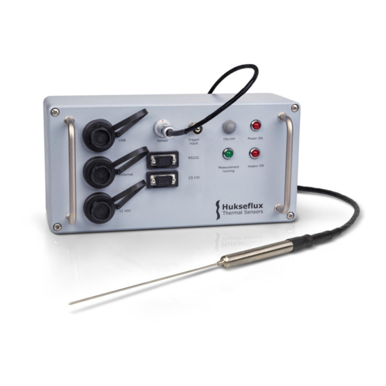
CPU drive contains the program that controls the measurement. The CRD drive contains the graphical user interface files and the measurement data. Figure 2.2.1 TPSYS20’s Measurement and Control Unit (MCU) Measurement model and data analysis When the heater is switched on at time t = 0 the temperature T will start to increase. - Page 16 Like the heating phase, the cooling phase is initially dominated by transient effects. This initial portion of the cooling phase data should likewise be discarded. TPSYS20 manual v2202 16/75...
- Page 17 More details about the theory of thermal needle probes can be found in Appendix 8.1. TPSYS20 is provided with a data analysis tool in the form of an MS Excel sheet that aids in the analysis of thermal conductivity data. The use of the data analysis tool is explained in Chapter 6.
-
Page 18: Specifications
Specifications Specifications of TPSYS20 TPSYS20 is a high accuracy measuring system for measuring the thermal conductivity of specimens. TPSYS20 specifications are listed in Table 3.1.1. TPSYS20 is delivered with either a TP02 or TP08 thermal needle probe. TP02 and TP08 can also be ordered separately. - Page 19 Table 3.1.1 Specifications of TPSYS20 (continued from previous page) TPSYS20 MCU SPECIFICATIONS Compatible Thermal Needle Probes • TP02 • TP08 Operating voltage 10 to 16 VDC Recommended operating voltage 12 VDC Typical current 100 to 500 × 10 Max. current...
- Page 20 Table 3.1.1 Specifications of TPSYS20 (continued from previous pages) CS I/O connector Connector type on MCU female DB9 connector Purpose for connecting TPSYS20 MCU to optional Campbell Scientific CR1000KD Keyboard/Display (not included with TPSYS20) POWER SUPPLY SPECIFICATIONS Power supply model...
- Page 21 Recommended specimen length > 160 mm > 80 mm Recommended minimum specimen volume > 1.3 L > 0.65 L Operating Conditions Rated operating temperature range -55 to +180 °C IP rating IP68 (needle and base) IP67 (entire probe) TPSYS20 manual v2202 21/75...
-
Page 22: Dimensions Of Tpsys20
Dimensions of TPSYS20 cable length cable length Figure 3.2.1 Dimensions of TPSYS20 in x 10 TPSYS20 manual v2202 22/75... -
Page 23: Installation And Connection
Figure 4.1.1 The components needed for hardware installation are: the thermal needle probe (1), the TPSYS20 MCU (2), the PSU (3), a USB or ethernet cable (4) and a laptop or PC with an ethernet connection or a USB port (5) TPSYS20 is primarily intended for laboratory use. -
Page 24: Opening The Graphical User Interface
4.2.1 USB connection To use this option, TPSYS20 MCU should be connected directly to a USB port on the PC. When using a USB connection, the Microsoft RNDIS protocol will be used to provide a ‘virtual ethernet link’ or ‘ethernet over USB’. -
Page 25: Setting The System Clock
URL in the web browser or to create shortcut on the desktop. 4.2.3 Logging into the TPSYS20 MCU To make sure the TPSYS20 MCU can only be controlled by the authorised users on a shared network, first time use in a new browser or PC requires the correct credentials. A pop-up will appear asking you to enter your credentials. -
Page 26: Setting The Net Frequency Filter
If a different thermal needle probe is connected to the MCU the parameters must be updated. See also Section 5.1. TPSYS20 manual v2202 26/75... - Page 27 In some cases, if the temperature of the environment in which TPSYS20 is used is not stable enough, the criterion may never be met. In that case a less strict criterion can be used at the expense of measurement accuracy.
- Page 28 The Summary of results box gives a brief overview of the results. For more detailed results view the Results tab. Figure 4.5.2.1 The measurement tab of the TPSYS20 graphical user interface 4.5.3 Results The Results tab is shown in Figure 4.5.3.1. The Results tab displays the results from the latest measurement that has been completed.
- Page 29 If the last measurement was not a calibration measurement, the box will not display any data other than the measured thermal conductivity. Figure 4.5.3.1 The results tab of the TPSYS20 graphical user interface 4.5.4 MCU settings The MCU settings tab is shown in Figure 4.5.4.1.
- Page 30 MCU temperature and the datalogger OS. The Net frequency filter box allows the user to set the net frequency filter for their region (either 50 or 60 Hz). Figure 4.5.4.1 The MCU settings tab of the TPSYS20 graphical user interface TPSYS20 manual v2202 30/75...
-
Page 31: Making Measurements
This chapter gives instructions on how to set the thermal needle probe parameters, how to perform calibration measurements, how to make thermal conductivity measurements using TPSYS20 and how to retrieve the results and raw data. It is assumed that the user has completed the installation and setup steps described in Chapter 4. -
Page 32: Thermal Needle Probe Calibration
Accept. Upon clicking Accept the system will set the values in the Current settings column if a predefined calibration reference was selected, or the system will copy the values from New settings columns if a custom calibration reference was selected. TPSYS20 manual v2202 32/75... - Page 33 The default value is 1.0 W/m. 4. Wait for the Temperature difference signal to become sufficiently stable. The Temperature difference signal can be found in the left graph on the Measurements tab. The required stability depends on the required accuracy, the TPSYS20 manual v2202 33/75...
- Page 34 6. Once the calibration measurement has completed select the Results tab and view the calibration results in the Calibration summary box. The calibration result is ok if the deviation is less than 5 %. Figure 5.2.2.1 The calibration summary box in the results tab TPSYS20 manual v2202 34/75...
-
Page 35: Thermal Conductivity Measurements
It is up to the user to determine if it is appropriate to deviate from the minimum recommended specimen dimensions. When the cooling phase data will be included in the final analysis the minimum required specimen size is larger relative to the minimum required specimen size if only the TPSYS20 manual v2202 35/75... - Page 36 For semi-hard materials or materials that are being casted special guiding tubes can be used (see Hukseflux GT series). The guiding tubes can be inserted into the material without the risk of damaging the thermal needle probe.
- Page 37 Measurements tab. 6. When the measurement has finished the results can be viewed in the Summary of results box in the Measurements tab and in more detail under the Results tab (see Section 5.3.3). TPSYS20 manual v2202 37/75...
- Page 38 • Heater power sufficient. – If this indicates a fail the temperature increase during the heating phase is too small. The signal-to-noise ratio may be low, TPSYS20 manual v2202 38/75...
- Page 39 • Thermal conductivity in measurement range. This check fails if the thermal conductivity falls outside thermal conductivity measuring range of the system (see specifications in Chapter 3). TPSYS20 manual v2202 39/75...
-
Page 40: Retrieving Measurement Data
Figure 5.3.3.1 The measurement quality checks box in the results tab The results displayed by the MCU should be considered preliminary results. Hukseflux strongly recommends downloading the raw data (see Section 5.4) and using the data analysis tool (see Chapter 6) to analyse the data and determine the final results. - Page 41 R_lambda_heating_cooling warning indicating that the thermal conductivity measured in the cooling phase differs by more than 5 % from the thermal conductivity measured in the TPSYS20 manual v2202 41/75...
- Page 42 °C, located halfway through the heated section of the needle T_cold the temperature of the cold reference joint in °C (TP02 only) sensitivity the sensitivity of the thermocouple in μV/K TPSYS20 manual v2202 42/75...
-
Page 43: Data Analysis
Data analysis As a first step in the analysis of measurement data, the TPSYS20 MCU automatically performs a simplified data analysis at the end of each measurement cycle. A second, more accurate and more detailed data analysis is performed by the user using the TPSYS20 data analysis tool which is included in each TPSYS20 measuring system delivery. - Page 44 Figure 6.1.1 The data analysis tool after it has been opened and a valid data set was imported and selected The main place for user input and output is the “results” tab. But before the actual analysis can be started, measurement data needs to be provided as explained in the next section. TPSYS20 manual v2202 44/75...
-
Page 45: Data Import
Copies of the tool can be kept retaining the data for later use or for archiving purposes. Figure 6.2.2 An example of a raw data file after importing the data into MS Excel TPSYS20 manual v2202 45/75... -
Page 46: Analysis Process
Attempts to edit or unlock these features may result in unexpected behaviour of the tool and unexpected output. Only the yellow cells can be edited for this reason. When a valid experiment ID is selected the “results” tabs looks similar to Figure 6.3.1. TPSYS20 manual v2202 46/75... - Page 47 Figure 6.3.1 Data analysis after selecting a valid experiment ID TPSYS20 manual v2202 47/75...
- Page 48 If “recalculate T_diff” is set to TRUE the excel sheet to recalculate T_diff from U_sen. If set to FALSE the excel sheet uses the T_diff values calculated by the TPSYS20 MCU. The default value is FALSE. The user does not normally have to set this parameter.
-
Page 49: Analysis Results
Analysis results The results of the analysis are all conveniently show on the “results” tab. Analysis results include the determined thermal conductivity, but also information about the TPSYS20 manual v2202 49/75... - Page 50 “Low” may mean that the signal is too low. “ igh” may mean that evaporation can affect the measurement if moist specimen are being measured. Low: T < 0.25 °C Medium: 0. ≤ T ≤ . °C High: T > 2.5 °C TPSYS20 manual v2202 50/75...
- Page 51 Thermal conductivity Indicates if the measured thermal conductivity is within the rated measuring range of the TPSYS20 system. Too low: λ < 0.1 W/(m·K) OK: 0. ≤ λ ≤ W/(m·K) Too high: λ > 6 W/(m·K) TPSYS20 manual v2202 51/75...
-
Page 52: Maintenance And Trouble Shooting
Maintenance and trouble shooting Recommended maintenance and quality assurance TPSYS20 measures reliably at a low level of maintenance. Unreliable measurement results are detected by scientific judgement, for example by looking for unreasonably large or small measured values. The preferred way to obtain a reliable measurement is a regular critical review of the measured data, preferably checking against other measurements. -
Page 53: Trouble Shooting
If necessary, use a less strict temperature stability criterion (at the expense of measurement accuracy). The temperature stability criterion can be set in the TPSYS20 web interface on the Measurement settings tab in Temperature stability assessment box. - Page 54 The time stamps in the The TPSYS20 MCU clock needs to be set. See Section 4.3 for instructions. “Results” and If this is a recurring problem without clear cause the internal battery may “RawData”...
-
Page 55: Appendices
Q only. TPSYS20 measures the temperature difference between the thermocouple hot junction located halfway through the heated section and either the thermocouple cold junction located in the tip of the needle (TP02) or the thermocouple reference junction in the base of the thermal needle probe (TP08). - Page 56 8.1.2 Thermal resistivity TPSYS20 is suitable for measuring the thermal resistivity of specimen. The thermal resistivity r is inversely proportional to the thermal conductivity λ: It has S.I. units of m∙K/W. Note that the thermal resistivity contains no additional information: once thermal conductivity is known the thermal resistivity is known and vice versa.
- Page 57 Typically the thermal diffusivity α of the material is not exactly known. In that case, to determine t and t either the thermal diffusivity is estimated or t and t are adjusted by trial-and-error until a satisfactory fit is found to the temperature-versus-logarithm-of- time data. TPSYS20 manual v2202 57/75...
-
Page 58: Uncertainty Assessment
0.75 % 1.73 CR1000X voltage readout accuracy 0.04 % of reading + 0.15 μV Heater power Heater resistance 1.00 % Shunt resistor tolerance 0.02 % 1.73 CR1000X voltage readout accuracy 0.04 % of reading + 0.5 μV TPSYS20 manual v2202 58/75... - Page 59 (in %) resulting from specimen temperature drift is: With a coverage factor k = 1 and with a and b given by: TPSYS20 manual v2202 59/75...
-
Page 60: Thermal Properties Of Some Common Materials
Standard reference data for the thermal conductivity of water; J. Phys. Chem. Ref. Data 24 (1995) p.1377-1381 [7.] E.W. Lemmon and R.T. Jacobsen; Viscosity and Thermal Conductivity Equations for Nitrogen, Oxygen, Argon, and Air; Int. J. Thermophys. 25 (2004) 21 TPSYS20 manual v2202 60/75... - Page 61 0.25 – 2.0 Sand, saturated 2.0 - 4.0 Clay, dry to moist 0.15 – 1.8 Clay, saturated 0.6 – 2.5 Soils with organic matter 0.15 – 2.0 Solid rocks 2.0 -7.0 Tuff (porous volcanic rock) 0.5 – 2.5 TPSYS20 manual v2202 61/75...
-
Page 62: Calibration
λ of the reference material and reference the observed thermal conductivity λ measured where R (new) is the newly calculated value for the heater resistance and R (old) TPSYS20 manual v2202 62/75... - Page 63 Commonly used reference materials Table 8.4.1.1 lists some commonly used thermal conductivity reference materials. TPSYS20 is supplied with a reference material container. The container can be used to calibrate the thermal needle probe against glycerol. The reference material container contains polyester fibres to inhibit diffusion. Glycerol is not included and must be purchased separately.
- Page 64 TPSYS20 is supplied with a reference material container that can be filled with glycerol. The container is supplied with polyester fibres to inhibit convection. Polymethylmethacrylate Hukseflux supplies CRC01 calibration reference cylinders (PMMA) containing a PMMA reference material. Polydimethylsiloxane PDMS is recommended as a reference material in the (PDMS) ASTM D5930-17 standard.
-
Page 65: Using The External Trigger Input
Figure 8.5.1 The External trigger box on the MCU settings tab NOTICE When using the external trigger input, do not exceed maximum input voltage. Exceeding the maximum trigger input voltage may permanently damage the TPSYS20 MCU. TPSYS20 manual v2202 65/75... -
Page 66: Tpsys20 Field Use
TPSYS20 field use TPSYS20 is primarily intended for laboratory use. With some additions however, TPSYS20 could be used in field experiments. For field use TPSYS20 could be power from a battery and operated using a portable laptop or a Campbell Scientific CR1000KD Keyboard/Display (see Figure 8.6.1). - Page 67 To use the Campbell Scientific CR1000KD Keyboard/Display it has to be connected to the DB9 connector labelled ‘CS I/O’ on the TPSYS20 MCU. It may be necessary to switch the TPSYS20 MCU power off and back on before the CR1000KD Keyboard/Display will function properly.
- Page 68 Heating time {R} Includes cooling data {R} Heater power {R} Statistical uncertainty {R} Thermal conductivity {R} Statistical uncertainty{R} All remarks R_Re {R} ▪ R_heat_time {R} ▪ R_heater_power {R} ▪ R_P_stability {R} ▪ R_P_Low {R} ▪ R_T_stability {R} ▪ TPSYS20 manual v2202 68/75...
- Page 69 1. navigate into the submenu ‘Change parameters’; 2. enter the new values in the corresponding fields; and finally 3. navigate to ‘Accept changes’ and select YES. For more information about the Campbell Scientific CR1000KD Keyboard/Display please refer to https://www.campbellsci.com/cr1000kd. TPSYS20 manual v2202 69/75...
-
Page 70: Thermal Needle Probe Wiring
Thermal needle probe wiring TP02 and TP08 thermal needle connectors are connected to TPSYS20 using a Fischer S 104 A055-130, 9 pin, male connector with internal part E3 104.2/6.7 + B. The wiring scheme is listed in Table 8.7.1. Table 8.7.1 Wiring of the Fischer connector. Note that TP08 does not have a tip thermocouple. -
Page 71: Loggerlink App
To use the LoggerLink App the TPSYS20 MCU must be connected to your ethernet network. 8.8.1 Finding the datalogger’s IP address In the LoggerLink app, you can search for TPSYS20 on your network using the search function under ‘TCP settings’. Figure 8.8.1.1 Using the LoggerLink app to find TPSYS20’s IP address 8.8.2 Setting the datalogger clock Connect to the TPSYS20 MCU using the Campbell Scientific LoggerLink app. -
Page 72: Campbell Scientific Device Configuration Utility
Communication Port field. This shows the dataloggers and their IP address in the network. When you have found the IP address of the TPSYS20, open your web browser and type the IP address in your address bar. Figure 8.9.1.1 Using the Device Configuration Utility to find TPSYS20’s IP address... - Page 73 8.9.2 Installing drivers manually Under Datalogger, select CR1000X series and click the Install USB Driver button, as illustrated in Figure 8.9.2.1 Figure 8.9.2.1 Using the Device Configuration Utility when drivers are not installed automatically TPSYS20 manual v2202 73/75...
-
Page 74: Eu Declaration Of Conformity
EU declaration of conformity Hukseflux Thermal Sensors B.V. Delftechpark 31 2628 XJ Delft The Netherlands in accordance with the requirements of the following directives: 2014/30/EU The Electromagnetic Compatibility Directive 2011/65/EU, The Restriction of Hazardous Substances Directive (EU) 2015/863 hereby declare under our sole responsibility that:... - Page 75 © 2022, Hukseflux Thermal Sensors B.V. www.huksefluxusa.com Hukseflux Thermal Sensors B.V. reserves the right to change specifications without notice.
Need help?
Do you have a question about the TPSYS20 and is the answer not in the manual?
Questions and answers