
Related Manuals for Hukseflux SR20-D2


Summary of Contents for Hukseflux SR20-D2
- Page 1 Hukseflux Thermal Sensors USER MANUAL SR20-D2 Digital secondary standard pyranometer with Modbus RTU and 4-20 mA output Copyright by Hukseflux | manual v2215 | www.hukseflux.com | info@hukseflux.com...
-
Page 2: Warning Statements
Putting more than 40 Volt across the sensor wiring of the current loop (4 to 20 mA) can lead to permanent damage to the sensor. For proper instrument grounding: use SR20-D2 with its original factory-made SR20-D2 cable. Using the same Modbus address for more than one device will lead to irregular behaviour of the entire network. -
Page 3: Table Of Contents
Site selection and installation Installation of the sun screen Electrical connection of SR20-D2: wiring diagram Grounding and use of the shield Using SR20-D2’s 4 to 20 mA output Connecting to an RS-485 network Connecting to a PC Communication with SR20-D2... - Page 4 Appendix on definition of pyranometer specifications Appendix on terminology / glossary 9.10 Appendix on floating point format conversion 9.11 Appendix on function codes, register and coil overview 9.12 EC declaration of conformity SR20-D2 manual v2215 4/72...
-
Page 5: List Of Symbols
Solar radiant exposure W∙h/m Time in hours Temperature coefficient 1/°C² Temperature coefficient 1/°C Temperature coefficient Output of 4-20 mA current loop Transmitted range of 4-20 mA output (see also appendix 9.6 on meteorological quantities) Subscripts Not applicable SR20-D2 manual v2215 5/72... -
Page 6: Introduction
Introduction SR20-D2 is a solar radiation sensor of the highest category in the ISO 9060 classification system: secondary standard. SR20-D2 is designed for the solar PV industry, offering two types of commonly used irradiance outputs: digital via Modbus RTU over RS-485 and analogue 4-20 mA (current loop). - Page 7 Modbus RTU over 2-wire RS-485 and analogue 4-20 mA output (current loop). For communication between a PC and SR20-D2, the Hukseflux Sensor Manager can be used. It allows the user to plot and export data, and change the SR20-D2 Modbus address and its communication settings. Figure 0.2 User...
- Page 8 This allows the user to choose his own local calibration service. The same feature may be used for remotely controlled re-calibration of pyranometers in the field. Ask Hukseflux for information on this feature and on ISO and ASTM standardised procedures for field calibration.
-
Page 9: Ordering And Checking At Delivery
Common options are: • Longer cable (in multiples of 5 m). Specify total cable length. Five silica gel bags in an air-tight bag for SR20-D2 desiccant holder. Specify order • number DC01. Adapted transmitted range for 4-20 mA output. Standard setting is 4 mA at 0 W/m •... -
Page 10: Quick Instrument Check
(see chapter on maintenance). 6. Check the instrument serial number as indicated by the software against the label on the instrument and against the certificates provided with the instrument. SR20-D2 manual v2215 10/72... -
Page 11: Instrument Principle And Theory
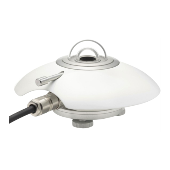
Instrument principle and theory Figure 2.1 Overview of SR20-D2: cable (standard length 5 metres, optional longer cable) fixation of sun screen (thumb screw) inner dome thermal sensor with black coating outer dome sun screen humidity indicator desiccant holder levelling feet... - Page 12 The thermopile sensor generates a voltage output signal that is proportional to the solar irradiance. in case of SR20-D2 the analogue thermopile voltage is converted by the instrument • electronics to a digital signal. In this process also the temperature dependence of the thermopile is compensated.
- Page 13 North East South West ISO secondary standard directional response limit zenith angle [°] Figure 2.3 Directional response of a SR20-D2 pyranometer of 4 azimuth angles, compared to secondary standard limits SR20-D2 manual v2215 13/72...
-
Page 14: Specifications Of Sr20-D2
Specifications of SR20-D2 3.1 Specifications of SR20-D2 SR20-D2 measures the solar radiation received by a plane surface from a 180 ° field of view angle. This quantity, expressed in W/m , is called “hemispherical” solar radiation. SR20-D2 offers irradiance in W/m as a digital output and as a 4-20 mA output. -
Page 15: Specifications Of Sr20-D2
Table 3.1.1 Specifications of SR20-D2 (continued) SR20-D2 ADDITIONAL SPECIFICATIONS Measurand hemispherical solar radiation Measurand in SI radiometry units irradiance in W/m Optional measurand sunshine duration Field of view angle 180 ° Output definition running average over 4 measurements, refreshed every 0.1 s... - Page 16 Table 3.1.1 Specifications of SR20-D2 (started on previous pages) CALIBRATION Calibration traceability to WRR Calibration hierarchy from WRR through ISO 9846 and ISO 9847, applying a correction to reference conditions Calibration method indoor calibration according to ISO 9847, Type IIc Calibration uncertainty <...
- Page 17 Table 3.1.1 Specifications of SR20-D2 (started on previous pages) Principle of 4 to 20 mA output 2-wire current loop. note: 2 additional wires are needed for the main supply of the sensor Rated operating voltage range of 4 to 20...
-
Page 18: Dimensions Of Sr20-D2
3.2 Dimensions of SR20-D2 M5 (2x) Figure 3.2.1 Dimensions of SR20-D2 in x 10 SR20-D2 manual v2215 18/72... -
Page 19: Standards And Recommended Practices For Use
4.3 General use for sunshine duration measurement According to the World Meteorological Organization (WMO, 2003), sunshine duration during a given period is defined as the sum of that sub-period for which the direct solar irradiance exceeds 120 W/m SR20-D2 manual v2215 19/72... -
Page 20: Specific Use For Outdoor Pv System Performance Testing
WMO-No. 8; Guide to Meteorological Instruments and Methods of Observation, chapter 8, measurement of sunshine duration, 8.2.2 Pyranometric Method 4.4 Specific use for outdoor PV system performance testing SR20-D2 is very well applicable in outdoor PV system performance testing. See also Hukseflux model SR30-D1 “next level digital secondary standard pyranometer”... -
Page 21: Installation Of Sr20-D2
Installation of SR20-D2 5.1 Site selection and installation Table 5.1.1 Recommendations for installation of pyranometers Location the situation that shadows are cast on the instruments is usually not desirable. The horizon should be as free from obstacles as possible. Ideally there should be no objects between the course of the sun and the instrument. -
Page 22: Installation Of The Sun Screen
5.2 Installation of the sun screen SR20-D2’s sun screen can be installed and removed by using the dedicated thumb screw. See item 2 of the drawing below. The thumb screw can be turned without tools for fixation or loosening of the sun screen, as visualised below. Once the thumb screw has turned the sun screen loose, the screen can be lifted off manually. -
Page 23: Electrical Connection Of Sr20-D2: Wiring Diagram
4 to 20 mA output (current loop), 10 to 40 VDC must be supplied to the designated pink and grey wires. Do not put more than 40 Volt across these wires. See chapter 5.5 for using SR20-D2’s 4 to 20 mA output. Wiring diagram of SR20-D2 Table 5.3.1... -
Page 24: Using Sr20-D2'S 4 To 20 Ma Output
5.5 Using SR20-D2’s 4 to 20 mA output SR20-D2 gives users the option to use 4 to 20 mA output instead of its digital output. When using 4 to 20 mA output, please read this chapter first. When opting solely for SR20-D2’s digital output, please continue with the next chapter. - Page 25 Usually a 100 Ω shunt resistor (R) is used to convert the current to a voltage. SR20-D2 operates on a supply voltage of 5 to 30 VDC. In addition, 10 to 40 VDC is needed for the 4 -20 mA function.
-
Page 26: Connecting To An Rs-485 Network
SR20-D2 is designed for a two-wire (half-duplex) RS-485 network. In such a network SR20-D2 acts as a slave, receiving data requests from the master. An example of the topology of an RS-485 two-wire network is shown in the figure below. SR20-D2 is powered from 5 to 30 VDC. - Page 27 , RS-485 B / B’ green [ - ] data, RS-485 A / A’ SR20-D2 wire RS-485 network Figure 5.6.2 Connection of SR20-D2 to an RS-485 network. SR20-D2 is powered by an external power supply of 5 to 30 VDC. SR20-D2 manual v2215 27/72...
-
Page 28: Connecting To A Pc
An external power supply is required to power the SR20-D2 (5 to 30 VDC). An RS-485 to USB converter is usually powered via the USB interface: in this case no external power is needed to feed the converter. -
Page 29: Communication With Sr20-D2
The Hukseflux Sensor Manager software provides a user interface for communication between a PC and SR20-D2. It allows the user to locate, configure and test one or more SR20-D2’s and to perform simple laboratory measurements using a PC. The Sensor Manager’s most common use is for initial functionality testing and modification of the... - Page 30 6.1.3 Sensor Manager: main window Figure 6.1.3.1 Main window of the Sensor Manager When the Sensor Manager is started and a SR20-D2 is connected to the PC, the user can communicate with the instrument. If the instrument address and communication settings are known, the serial connection settings and the Modbus address can be entered directly.
- Page 31 Modbus address in the main window to the values of the instrument, and then clicking “Connect”. Figure 6.1.3.2 Sensor Manager main window with three connected SR20-D2’s When an instrument is found, temperature and irradiance data are displayed. Updates are done manually or automatically.
- Page 32 . The Y-axis automatically scales to display the full measured range. irradiance in W/m Figure 6.1.4.1 Example of a SR20-D2 irradiance plot in the Sensor Manager 6.1.5 Sensor Manager: information about the instrument The main window shows the “Show details” button, giving access to the “Sensor details”...
- Page 33 6.1.6 Sensor Manager: changing Modbus address and communication settings In the “Sensor details” window the “Change serial settings” function opens the “Change serial communication settings” window, as shown in the figure below. Figure 6.1.6.1 Change serial communication settings window in the Sensor Manager SR20-D2 manual v2215 33/72...
-
Page 34: Network Communication: Function Codes, Registers, Coils
Example: During a calibration experiment, the result might be that SR20-D2 has an irradiance output in W/m that is 990, whereas the standard indicates it should be 970. The SR20-D2 output is in this example 2.06 % too high. The original sensitivity of 16.15 x 10 V/(W/m ) ought to be changed to 16.48, using registers 41 + 42. - Page 35 An Unsigned 32 bit integer can be calculated by the formula: (MSW x 2 )+LSW = U32. An example of such a calculation is available in the paragraph “Network communication: example master request to SR20-D2”. SR20-D2 manual v2215 35/72...
- Page 36 Your data request may need an offset of +1 for each SR20-D2 register number, depending on processing by the network master. Example: SR20-D2 register number 7 + master offset = 7 + 1 = master register number 8. Consult the manual of the device acting as the local master.
- Page 37 Provides the sensor output in 0.01 W/m², not compensated for temperature dependence. The data must be divided by 100 to get the value in W/m². Hukseflux recommends not to use this data. MSW and LSW should be read together in one request.
- Page 38 Ω. Register 46 + 47, Sensor calibration date, last sensor calibration date, from which the sensitivity in register 41 and 42 was found, in YYYYMMDD. Register 61, Firmware version. Register 62, Hardware version. SR20-D2 manual v2215 38/72...
- Page 39 PARAMETER DESCRIPTION OF CONTENT TYPE FORMAT OF DATA NUMBER 83 + 84 Directional response Directional response measurement date measurement date in YYYYMMDD Directional response measurement employee Register 83 to 85, these registers are for reference purposes. SR20-D2 manual v2215 39/72...
- Page 40 Register 86 to 95, these registers are for reference purposes. Please note that if your data request needs an offset of +1 for each SR20-D2 register number, depending on processing by the network master, this offset applies to coils as well. Consult the manual of the device acting as the local master.
- Page 41 After the measurement, a new value will be written into register 7. Requesting to write this coil with a high repetition rate will result in irregular behaviour of the sensor; the check must be executed as an exceptional diagnostics routine only. SR20-D2 manual v2215 41/72...
-
Page 42: Network Communication: Getting Started
Modbus device. This usually consists of defining a request that can be broadcast by the master. If the SR20-D2 is not already defined as a standard sensor type on the network, contact the supplier of the network equipment to see if a library file for the SR20-D2 is available. -
Page 43: Network Communication: Example Master Request To Sr20-D2
For quality assurance also the sensor serial number, register 40 and the temperature in register 6, are useful. In this example a SR20-D2 has address 64. The example requests the solar radiation (temperature compensated) register 2 + 3, sensor serial number, register 40, and the temperature of the instrument register 6. - Page 44 Together, register 2 and 3 are representing the temperature compensated solar radiation output measured by the SR20-D2. The MSW is in register 2 and the LSW in 3. The output has to be calculated by the formula: ((MSW x 2 ) + LSW)/100.
- Page 45 [03] = Modbus function [02] = Number of bytes [0A][29] = Content of register 40, decimal equivalent = 2601 [43][35] = CRC Register 40 represents the sensors serial number. In this example the serial number is 2601. SR20-D2 manual v2215 45/72...
-
Page 46: Making A Dependable Measurement
* defined at Hukseflux as all factors outside the instrument that are relevant to the measurement such as the cloud cover (presence or absence of direct radiation), sun position, the local horizon (which may be obstructed) or condition of the ground (when tilted). -
Page 47: Reliability Of The Measurement
For first class and secondary standard models (for instance model SR11 first class pyranometer and SR20-D2 digital secondary standard pyranometer) extra desiccant (in a set of 5 bags in an air tight bag) is available. -
Page 48: Speed Of Repair And Maintenance
Dependability is not only a matter of reliability but also involves the reaction to problems; if the processing time of service and repairs is short, this contributes to the dependability. Hukseflux pyranometers are designed to allow easy maintenance and repair. The main maintenance actions are: replacement of desiccant •... - Page 49 3) A separate estimate has to be entered to allow for estimated uncertainty due to the instrument maintenance level. 4) The calibration uncertainty has to be entered. Please note that Hukseflux calibration uncertainties are lower than those of alternative equipment. These uncertainties are entered in measurement equation (equation is usually Formula 0.1: E = U/S), either as...
- Page 50 Table 7.4.1.1 Preliminary estimates of achievable uncertainties of measurements with Hukseflux pyranometers. The estimates are based on typical pyranometer properties and calibration uncertainty, for sunny, clear sky days and well maintained stations, without uncertainty loss due to lack of maintenance and due to instrument fouling. The table specifies expanded uncertainties with a coverage factor of 2 and confidence level of 95 %.
-
Page 51: Maintenance And Trouble Shooting
Maintenance and trouble shooting 8.1 Recommended maintenance and quality assurance SR20-D2 can measure reliably at a low level of maintenance in most locations. Usually unreliable measurements will be detected as unreasonably large or small measured values. As a general rule this means that regular visual inspection combined with a critical review of the measured data, preferably checking against other measurements, is the preferred way to obtain a reliable measurement. -
Page 52: Trouble Shooting
ISO 9847 or outdoors according to ISO9846 8.2 Trouble shooting Table 8.2.1 Trouble shooting for SR20-D2 (continued on next page) General Inspect the instrument for any damage. Inspect if the humidity indicator is blue. Blue indicates dryness. The colour pink indicates it is humid: in the latter case replace the desiccant (see chapter on maintenance). -
Page 53: Calibration And Checks In The Field
The applicable standard is ISO 9847 “International Standard- Solar Energy- calibration of field pyranometers by comparison to a reference pyranometer”. At Hukseflux an indoor calibration according to the same standard is used. Hukseflux recommendation for re-calibration: if possible, perform calibration indoor by comparison to an identical reference instrument, under normal incidence conditions. -
Page 54: Data Quality Assurance
2 to 3 days under cloudless conditions, 10 days under cloudy conditions. In general this is not achievable. In order to shorten the calibration process Hukseflux suggests to allow calibration at normal incidence, using hourly totals near solar noon. - Page 55 SR20-D2 manual v2215 55/72...
-
Page 56: Appendices
Appendices 9.1 Appendix on cable extension / replacement The sensor cable of SR20-D2 is equipped with a M16 straight connector. In case of cable replacement, it is recommended to purchase a new cable with connector at Hukseflux. An alternative is to choose for a Do-it-yourself (DIY) approach; please ask for the DIY connector assembly guide. -
Page 57: Appendix On Tools For Sr20-D2
Table 9.1.1 Preferred specifications for SR20-D2 cable replacement and extension General replacement please order a new cable with connector at Hukseflux or choose for a DIY approach. In case of DIY replacement by the user see connector specifications below and ask for the DIY connector assembly guide... -
Page 58: Appendix On Spare Parts For Sr20-D2
O-ring SR20-D2 • NOTE: Outer dome, level and sensor of SR20-D2 cannot be supplied as spare parts. In case of possible damage to the SR20-D2, after repair the instrument must be tested to verify performance within specification limits. This is required by ISO 9060. -
Page 59: Appendix On Standards For Classification And Calibration
Indoor Transfer of Calibration from Reference to Field Pyranometers ISO 9059:1990 Solar energy -- Calibration of ASTM E 816 Standard Test Method for field pyrheliometers by comparison to a Calibration of Pyrheliometers by Comparison to reference pyrheliometer Reference Pyrheliometers SR20-D2 manual v2215 59/72... -
Page 60: Appendix On Calibration Hierarchy
(transfer error). The coverage factor must be determined; at Hukseflux we work with a coverage factor k = 2. SR20-D2 manual v2215... -
Page 61: Appendix On Meteorological Radiation Quantities
In solar energy radiant exposure is often given in W∙h/m Table 9.6.1 Meteorological radiation quantities as recommended by WMO (additional symbols by Hukseflux Thermal Sensor). POA stands for Plane of Array irradiance. The term originates from ASTM and IEC standards. -
Page 62: Appendix On Iso And Wmo Classification Tables
WMO 7.3.2.5: Table 7.5 lists the expected maximum deviation from the true value, excluding calibration errors. ** At Hukseflux the expression ± 1 % is used instead of a range of 2 %. *** an instrument is subject to conformity testing of its specifications. Depending on the classification, conformity compliance can be proven either by group- or individual compliance. - Page 63 Zero offset a: response to 200 W/m net thermal radiation (ventilated). (200 W/m Hukseflux assumes that unventilated instruments have to 9060- thermal specify the zero-offset in unventilated – worst case – conditions. 1990 radiation ) Zero offsets are a measure of the stability of the zero-point.
- Page 64 The former is the direct component, the latter is the diffuse component of the solar radiation. (ref: WMO, Hukseflux) Hemispherical solar radiation received by a plane surface from a 180° field of view angle (solid solar radiation angle of 2 π...
- Page 65 9.10 Appendix on floating point format conversion For efficient use of microcontroller capacity some registers in the SR20-D2 contain data in a float or floating point format. In fact, a floating point is an approximation of a real number represented by a number of significant digits (mantissa) and an exponent. For implementation of the floating point numbers, Hukseflux follows the IEEE 754 standard.
- Page 66 0x10 Write Multiple Registers Your data request may need an offset of +1 for each SR20-D2 register number, depending on processing by the network master. Example: SR20-D2 register number 7 + master offset = 7 + 1 = master register number 8. Consult the manual of the device acting as the local master.
- Page 67 79 + 80 Sensor sensitivity See register 63 + 64 Float history 5 81 + 82 Calibration date history See register 65 + 66 83 + 84 Directional response Directional response measurement date measurement date in YYYYMMDD SR20-D2 manual v2215 67/72...
- Page 68 Up to five 16 bit registers can be requested in one request. If requesting six or more registers, use multiple requests. Please note that if your data request needs an offset of +1 for each SR20-D2 register number, depending on processing by the network master, this offset applies to coils as well.
- Page 69 9.12 EU declaration of conformity Hukseflux Thermal Sensors B.V. Delftechpark 31 2628 XJ Delft The Netherlands in accordance with the requirements of the following directive: 2011/65/EU The Restriction of Hazardous Substances Directive 2014/30/EU The Electromagnetic Compatibility Directive hereby declare under our sole responsibility that:...
- Page 71 © 2022, Hukseflux Thermal Sensors B.V. www.hukseflux.com Hukseflux Thermal Sensors B.V. reserves the right to change specifications without notice.
- Page 72 SR20-D2 manual v2215 2/72...
Need help?
Do you have a question about the SR20-D2 and is the answer not in the manual?
Questions and answers