
Subscribe to Our Youtube Channel
Related Manuals for Hukseflux SR05 series


Summary of Contents for Hukseflux SR05 series
- Page 1 Hukseflux Thermal Sensors USER MANUAL SR05-D1A3-PV Digital second class pyranometer – alternative for PV reference cell Copyright by Hukseflux | manual v1801 | www.hukseflux.com | info@hukseflux.com...
-
Page 2: Warning Statements
Warning statements Putting more than 30 Volt across the sensor wiring of the main power supply can lead to permanent damage to the sensor. Keep the voltage on the RS-485 data wiring of SR05-D1A3-PV between -7 and +12 V to avoid permanent damage. -
Page 3: Table Of Contents
Communication with SR05 PC communication: Sensor Manager software Network communication: function codes, registers, coils Silicon Reference Cell compatible Modbus output Standard Hukseflux Modbus Output Network communication: getting started Network communication: example master request to SR05 Making a dependable measurement The concept of dependability... - Page 4 Appendix on standards for classification and calibration Appendix on calibration hierarchy Appendix on meteorological radiation quantities Appendix on ISO and WMO classification tables Appendix on definition of pyranometer specifications Appendix on terminology / glossary 9.10 Appendix on floating point format conversion 9.11 Appendix on function codes, register and coil overview 9.12...
-
Page 5: List Of Symbols
List of symbols Quantities Symbol Unit Voltage output Sensitivity V/(W/m Solar irradiance Output of 0-1 V Transmitted range of 0-1 V (see also appendix 9.6 on meteorological quantities) Subscripts Not applicable Notation Example Decimal numbers are indicated without prefix Hexadecimal numbers are indicated with a 0x prefix 0x1E SR05-D1A3-PV manual v1801 5/83... -
Page 6: Introduction
This user manual covers use of SR05-D1A3-PV. Specifications of this version differ from those of the other digital and analogue sensors in the SR05 series range. For use of SR05-D1A3 or SR05-D2A2, consult the separate SR05-D1A3 & SR05-D2A2 user manual. For use of SR05-A1, offering analogue millivolt output, consult the separate SR05-A1 user manual. - Page 7 Model SR05-D1A3-PV has a digital output that is identical to the most commonly used photovoltaic reference cell with Modbus over RS-485 output. This allows for easy installation in existing PV monitoring systems, without the need to make major modifications to data logging software, instrument libraries and infrastructure. Compared to silicon reference cells, pyranometers offer several advantages such as a perfect (cosine) directional response and a flat spectral response over a wide range.
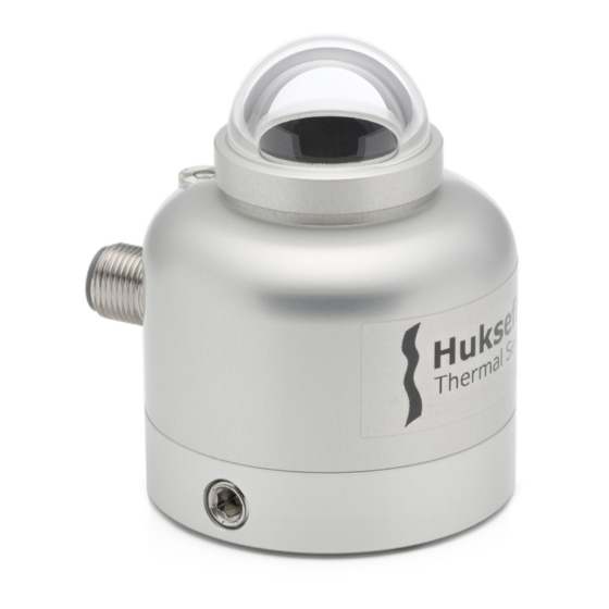
- Page 8 SR05-D1A3-PV design SR05 pyranometers employ a thermopile sensor with black coated surface, one dome and an anodised aluminium body with visible bubble level. Optionally the sensor can be delivered with a unique ball levelling mechanism and tube mount or dedicated mounting fixture, for easy installation.
- Page 9 Communication with a PC: Hukseflux Sensor Manager Software For communication between a PC and SR05-D1A3-PV(‘s), the Hukseflux Sensor Manager software can be used. It is available for download on our website. The software allows the user to quickly configure SR05-D1A3-PV Modbus address and serial communication settings (baud rate, parity and stopbits) and to plot and export data.
- Page 10 SR05 are accessible for users with a password. This allows the user to choose his own local calibration service. The same register access may also be used for remotely controlled re-calibration of pyranometers in the field. Ask Hukseflux for information on this feature and on ISO and ASTM standardised procedures for field calibration.
-
Page 11: Ordering And Checking At Delivery
SR05-D1A3-PV second class pyranometer has a digital output that is identical to the most commonly used photovoltaic reference cell with Modbus over RS-485 output. Besides SR05-D1A3-PV, SR05 series offers several other versions with industry standard outputs, both digital and analogue. Each version offers multiple mounting options and... - Page 12 Table 1.1.1 Ordering codes for the versions of model SR05 VERSIONS OF SR05 (part numbers), without cable SR05-D1A3-PV digital second class pyranometer, with Modbus over RS-485 output, alternative for PV reference cell SR05-D1A3-PV-BL digital second class pyranometer, with Modbus over RS-485 output, alternative for PV reference cell, with ball levelling SR05-D1A3-PV-TMBL...
-
Page 13: Included Items
2 x M5x30 bolts • 2 x M5x40 bolts • Please store the certificate in a safe place. The Hukseflux Sensor Manager can be downloaded via www.hukseflux.com/downloads SR05-D1A3-PV SR05-D1A3-PV-BL SR05-D1A3-PV-TMBL Figure 1.2.1 From left to right: SR05-D1A3-PV, SR05-D1A3-PV-BL and SR05-D1A3-PV-... -
Page 14: Quick Instrument Check
1.3 Quick instrument check A quick test of the instrument can be done by connecting it to a PC and installing the Sensor Manager software. See the chapters on installation and PC communication for directions. 1. At power–up the signal may have a temporary output level different from zero; an offset. -
Page 15: Instrument Principle And Theory
Instrument principle and theory Figure 2.1 Overview of SR05: shaded areas in exploded view show ball levelling mount and shim cable (standard length 3 metres, optional longer cable) connector bubble level thermal sensor with black coating glass dome sensor body tube mount (optional) mounting screw (included with ball levelling and tube mount;... - Page 16 SR05’s scientific name is pyranometer. A pyranometer measures the solar radiation received by a plane surface from a 180 ° field of view angle. This quantity, expressed in , is called “hemispherical” solar radiation. The solar radiation spectrum extends roughly from 285 to 3000 x 10 m.
- Page 17 solar radiation pyranometer response 1000 10000 wavelength [x 10 Figure 2.2 Spectral response of the pyranometer compared to the solar spectrum. The pyranometer only cuts off a negligible part of the total solar spectrum. SR05-D1A3-PV manual v1801 17/83...
-
Page 18: Specifications Of Sr05-D1A3-Pv
0-1 V signal. This user manual covers use of SR05-D1A3-PV. Specifications of this version differ from those of the other digital and analogue sensors in the SR05 series range. For use of SR05-D1A3 or SR05-D2A2, consult the separate SR05-D1A3 &... - Page 19 Connector protection class IP67 Cable replacement replacement and extension cables with connector(s) can be ordered separately from Hukseflux Mounting (see options) 2 x M5 bolt at 46 mm centre-to-centre distance on north-south axis, requires 4 mm hex key Levelling (see options)
- Page 20 Java Runtime Environment 8 – latest version available free of charge at http://www.java.com, Hukseflux Sensor Manager - software version v1817 or higher User interface on PC Hukseflux Sensor Manager v1817 or higher software downloadable: to download and for available software updates, see http://www.hukseflux.com/page/downloads...
- Page 21 4 m hex key for levelling and mounting option code = TMBL Alternative pyranometer mounting for mounting any Hukseflux pyranometer on fixture horizontal and vertical tubes, on platforms, both horizontal and in Plane of Array order code = PMF01...
-
Page 22: Dimensions Of Sr05
3.2 Dimensions of SR05 Figure 3.2.1 Dimensions of SR05 in x 10 m. The bottom drawing shows the height of SR05 combined with its optional ball levelling mount and the tube diameter required for use with SR05’s optional tube mount. M5 mounting bolts and the countersunk set screw require a 4 mm hex key for mounting and levelling. -
Page 23: Standards And Recommended Practices For Use
Standards and recommended practices for use Pyranometers are classified according to the ISO 9060 standard and the WMO-No. 8 Guide. In any application the instrument should be used in accordance with the recommended practices of ISO, IEC, WMO and / or ASTM. 4.1 Classification standard Table 4.1.1 Standards for pyranometer classification. -
Page 24: Specific Use For Outdoor Pv System Performance Testing
IEC 61724-1) • horizontally, for measurement of the global horizontal irradiance (E, also noted as GHI in IEC 61724-1) SR05 series is applicable in outdoor PV system performance testing. See also Hukseflux model SR15-D1 “digital first class pyranometer” and SR30-D1 “digital secondary... -
Page 25: Specific Use In Meteorology And Climatology
4.5 Specific use in meteorology and climatology The World Meteorological Organization (WMO) is a specialised agency of the United Nations. It is the UN system's authoritative voice on the state and behaviour of the earth's atmosphere and climate. WMO publishes WMO-No. 8; Guide to Meteorological Instruments and Methods of Observation, in which a table is included on “level of performance”... -
Page 26: Installation Of Sr05
Installation of SR05 5.1 Site selection and installation Table 5.1.1 Recommendations for installation of pyranometers Location the situation that shadows are cast on the instruments is usually not desirable. The horizon should be as free from obstacles as possible. Ideally there should be no objects between the course of the sun and the instrument. -
Page 27: Mounting And Levelling Sr05
5.2 Mounting and levelling SR05 SR05 in its standard configuration is equipped with a visible bubble level and two mounting holes. For easy mounting and levelling on a (non-)horizontal surface, SR05’s optional ball levelling is recommended. Ball levelling offers: easy levelling •... -
Page 28: Installing Sr05 With Its Ball Levelling And Tube Mount
5.4 Installing SR05 with its ball levelling and tube mount Two M5x20 bolts and two M5 nuts are included with SR05’s ball levelling option. These are to be used to mount SR05 with its ball levelling to a (non-)horizontal surface. Two M5x30 bolts and two M5x40 bolts are included with SR05’s tube mount with ball levelling. - Page 29 Hold SR05 in one hand, the ball levelling mount in the other. Separate SR05 from the ball levelling mount by gently pulling out the ball levelling mount. Mount the ball levelling to a surface or platform with its M5 bolts and nuts. See chapter on tooling required.
-
Page 30: Placing And Removing Sr05'S Ball Levelling Shim
When retrofitting SR05 or when ordering SR05 pyranometer and its optional ball levelling in separate orders, the user has to ensure a shim is placed properly in the centre of the bottom plate of SR05. The shim allows smooth levelling. Read the following chapter on placing and removing the shim. - Page 31 Pinch the shim slightly in order to reduce its diameter and to make it fit easily into SR05’s bottom plate. While pinching, push the shim into its position on SR05’s bottom plate. The shim is placed. For mounting and levelling, continue with the following steps: Mount the ball levelling with its mounting bolts.
-
Page 32: Electrical Connection Of Sr05-D1A3-Pv: Wiring Diagram
(Modbus over RS-485) and as an analogue 0 to 1 V output. This user manual covers use of SR05-D1A3-PV. Specifications of this version differ from those of the other digital and analogue sensors in the SR05 series range. For use of SR05-D1A3 or SR05-D2A2, consult the separate SR05-D1A3 &... -
Page 33: Using Sr05-D1A3-Pv's Digital Output
5.8 Using SR05-D1A3-PV’s digital output SR05-D1A3-PV can be read out either via its digital output or via its analogue output. When opting for the analogue output, please refer to the next section. This section describes how to use the digital output. When using SR05’s digital output, SR05-D1A3-PV can be connected to an RS-485 network. - Page 34 defined state when no transmission is occurring, a pull up and pull down resistor are recommended. Typical values for both resistors are in the range from 650 to 850 Ω. not connected blue shield yellow [+] 5 to 30 VDC brown [ - ] 5 to 30 VDC black...
- Page 35 5.8.2 Connecting SR05-D1A3-PV to a PC SR05-D1A3-PV can be accessed via a PC. In that case communication with the sensor can be done via the user interface offered by the Sensor Manager software (see the next chapters) or by any other Modbus testing tool. Depending on the available ports on the PC, either an RS-485 to USB converter or an RS- 485 to RS-232 converter is used.
-
Page 36: Using Sr05-D1A3-Pv's Analogue 0 To 1 V Output
5.9 Using SR05-D1A3-PV’s analogue 0 to 1 V output SR05-D1A3-PV gives users the option to use 0 to 1 V output instead of its digital output. This section explains how to use the 0 to 1 V output. When opting solely for SR05-D1A3-PV’s digital output, please refer to section 5.8. -
Page 37: Communication With Sr05
Hukseflux Modbus registers are available with an offset in the register address. 6.1 PC communication: Sensor Manager software The digital SR05 series can be accessed via a PC. In that case the communication with the sensor is done via the user interface offered by the Hukseflux Sensor Manager software or by another Modbus testing tool. - Page 38 6.1.2 Trouble shooting during Sensor Manager installation When Java Runtime Environment software is not installed, a Windows message • comes up, displaying “the file “Hukseflux_Sensor_Manager.jar” could not be opened”. The solution is to install Java Runtime Environment on the PC and try again.
- Page 39 Once the Modbus address is set, click “Connect” to establish contact with the instrument. Note: the “Auto-detect Hukseflux” option in the “Sensor type” drop down box, the “Find First” button and the “Find All” button only work for standard Hukseflux sensors and will not work for model SR05-D1A3-PV.
- Page 40 are displayed. When the “update interval” is 1 second, the “Show tail only” function is available after around 10 minutes of data collection. The y-axis displays the measured irradiance in W/m . The Y-axis automatically scales to display the full measured range. Figure 6.1.4.1 Example of an SR05 irradiance plot in the Sensor Manager.
- Page 41 Figure 6.1.5.1 Sensor details window in the Sensor Manager. 6.1.6 Sensor Manager: changing Modbus address and communication settings In the “Sensor details” window the “Change serial settings” function opens the “Change serial communication settings” window, as shown in the figure below. SR05-D1A3-PV manual v1801 41/83...
- Page 42 Figure 6.1.6.1 Change serial communication settings window in the Sensor Manager When new communication settings or a new Modbus address are entered, these need to be confirmed by clicking “Change settings”. The instrument will then automatically restart. In case the “Change settings” function is not activated, the original settings remain valid.
-
Page 43: Network Communication: Function Codes, Registers, Coils
6.2 Network communication: function codes, registers, coils Warning: Using the same Modbus address for more than one device will lead to irregular behaviour of the entire network. This chapter describes function codes, data model and registers used in the SR05-D1A3-PV firmware. Communication is organised according to the specifications provided by the Modbus Organization. - Page 44 Table 6.2.3 Format of data FORMAT OF DATA DESCRIPTION Unsigned 16 bit integer Signed 16 bit integer Unsigned 32 bit integer Signed 32 bit integer Float IEEE 754 32 bit floating point format String A string of ASCII characters The data format includes signed and unsigned integers. The difference between these types is that a signed integer passes on negative values, which reduces the range of the integer by half.
-
Page 45: Silicon Reference Cell Compatible Modbus Output
6.3 Silicon Reference Cell compatible Modbus output SR05-D1A3-PV has an IMT-Solar Si-RS485TC-T-MB silicon reference cell compatible Modbus output. The corresponding input registers, diagnostic function and serial communication settings are explained below. 6.3.1 Input registers (0x04) Table 6.3.1.1 PV reference cell compatible input registers. MODBUS REGISTERS 0x0000-0x0008 REGISTER PARAMETER... - Page 46 6.3.3 Serial communication settings (0x46) Function code 0x46 allows the user to set the device address and to read and write the serial settings. This section gives a description of the usage of function code 0x46 with sub function codes 0x04, 0x05 and 0x06. Sub function 0x04: write device address Sub function code 0x04 is used to change the device address.
- Page 47 Modbus request: Device address 1 Byte 1 to 247 Function code 1 Byte 0x46 Sub function code 1 Byte 0x06 Baud rate 1 Byte 0 to 4, see table 6.3.3.1 Bit frame 1 Byte 0 to 3, see table 6.3.3.2 Checksum 2 Byte CRC16...
-
Page 48: Standard Hukseflux Modbus Output
6.4 Standard Hukseflux Modbus Output In addition to the IMT-Solar Si-RS485TC-T-MB silicon reference cell compatible Modbus output, SR05-D1A3-PV supports the standard Hukseflux Modbus output, but with an offset of 0x1000 in the register address as compared to SR05-D1A3: SR05-D1A3-PV register address = SR05-D1A3 register address + 0x1000 Table 6.4.1 Modbus registers 0x1000 to 0x100B. - Page 49 10 to get the value in Ω. This register returns a 0 by default. To read the resistance, first a measurement has to be performed. This can be done by writing 0xFF00 to coil 2. Hukseflux recommends to use this function only when necessary for diagnostics in case of sensor failure.
- Page 50 Register 0x1009, Scaling factor temperature, default scaling factor is 100. Register 0x100A + 0x100B, Sensor voltage output, sensor voltage output signal of the thermopile in x 10 Table 6.4.3 Modbus registers 0x1020 to 0x103E, sensor and calibration information MODBUS REGISTERS 0x1020-0x103E REGISTER PARAMETER DESCRIPTION OF CONTENT...
- Page 51 Register 0x103D, Firmware version. Register 0x103E, Hardware version. Table 6.4.4 Modbus registers 0x103F to 0x1052, calibration history MODBUS REGISTERS 0x103F-0x1052 REGISTER PARAMETER DESCRIPTION OF TYPE FORMAT ADDRESS CONTENT OF DATA (HEX) (R/W) 0x103F + Sensor sensitivity history 1 In x 10 V/(W/m Float 0x1040...
- Page 52 Table 6.4.5 Coils COILS COIL PARAMETER DESCRIPTION TYPE OF OBJECT TYPE Restart Restart the sensor Single bit Reserved Check Measure sensor Single bit electrical resistance Coil 0, Restart, when 0xFF00 is written to this coil the sensor will restart. If applied, a new Modbus address or new serial settings will become effective.
-
Page 53: Network Communication: Getting Started
6.5 Network communication: getting started Once it has the correct Modbus address and communication settings, SR05-D1A3-PV can be connected directly to an RS-485 network and a power supply. How to physically connect a sensor as a slave in a Modbus network is shown in section 5.11: Connecting a SR05-D1A3-PV to an RS-485 network. -
Page 54: Network Communication: Example Master Request To Sr05
6.6 Network communication: example master request to SR05 Normal sensor operation consists of requesting the output of registers 0x1002 + 0x1003; the temperature compensated solar radiation. For quality assurance also the sensor serial number, register 0x1028 and the temperature in register 0x1006, are useful. In this example a SR05-D1A3-PV has address 64. - Page 55 Request for body temperature, register 0x1006: Master Request: 0x40 0x03 0x1006 0x0001 0x6FDA 0x40 = Modbus Slave address 0x03 = Modbus function 0x1006 = Start register 0x0001 = Number of registers 0x6FDA = CRC Sensor response: 0x40 0x03 0x02 0x08B1 0x43FF 0x40 = Modbus Slave address 0x03 = Modbus function 0x02 = Number of bytes...
-
Page 56: Making A Dependable Measurement
* defined at Hukseflux as all factors outside the instrument that are relevant to the measurement such as the cloud cover (presence or absence of direct radiation), sun position, the local horizon (which may be obstructed) or condition of the ground (when tilted). -
Page 57: Reliability Of The Measurement
7.2 Reliability of the measurement A measurement is reliable if it measures within required uncertainty limits for most of the time. We distinguish between two causes of unreliability of the measurement: related to the reliability of the pyranometer and its design, manufacturing, calibration •... -
Page 58: Speed Of Repair And Maintenance
Dependability is not only a matter of reliability but also involves the reaction to problems; if the processing time of service and repairs is short, this contributes to the dependability. Hukseflux pyranometers are designed to allow easy maintenance and repair. The main maintenance actions are: replacement of desiccant •... - Page 59 3) A separate estimate has to be entered to allow for estimated uncertainty due to the instrument maintenance level. 4) The calibration uncertainty has to be entered. Please note that Hukseflux calibration uncertainties are lower than those of alternative equipment. These uncertainties are entered in measurement equation (equation is usually Formula 0.1: E = U/S), either as...
- Page 60 Table 7.4.1.1 Preliminary estimates of achievable uncertainties of measurements with Hukseflux pyranometers. The estimates are based on typical pyranometer properties and calibration uncertainty, for sunny, clear sky days and well maintained stations, without uncertainty loss due to lack of maintenance and due to instrument fouling. The table specifies expanded uncertainties with a coverage factor of 2 and confidence level of 95 %.
-
Page 61: Maintenance And Trouble Shooting
Maintenance and trouble shooting 8.1 Recommended maintenance and quality assurance SR05 can measure reliably at a low level of maintenance in most locations. Usually unreliable measurements will be detected as unreasonably large or small measured values. As a general rule this means that regular visual inspection combined with a critical review of the measured data, preferably checking against other measurements, is the preferred way to obtain a reliable measurement. -
Page 62: Trouble Shooting
MINIMUM RECOMMENDED PYRANOMETER MAINTENANCE (continued) 6 years parts if applicable / necessary replace the parts that are most replacement exposed to weathering; cable, connector. NOTE: use Hukseflux approved parts only internal if applicable: open instrument and inspect / replace O-rings; inspection... -
Page 63: Calibration And Checks In The Field
The applicable standard is ISO 9847 “International Standard- Solar Energy- calibration of field pyranometers by comparison to a reference pyranometer”. At Hukseflux an indoor calibration according to the same standard is used. Hukseflux recommendation for re-calibration: if possible, perform calibration indoor by comparison to an identical reference instrument, under normal incidence conditions. -
Page 64: Data Quality Assurance
Hukseflux main recommendations for field intercomparisons are: 1) to take normal incidence as a reference and not the entire day. 2) to take a reference of the same brand and type as the field pyranometer or a pyranometer of a higher class, and 3) to connect both to the same electronics, so that electronics errors (also offsets) are eliminated. - Page 65 SR05-D1A3-PV manual v1801 65/83...
-
Page 66: Appendices
Appendices 9.1 Appendix on cable extension / replacement The sensor cable of the SR05 series is equipped with a M12-A straight connector. In case of cable replacement, it is recommended to purchase a new cable with connector at Hukseflux. In case of cable extension, it is recommended to purchase an extension cable with connector pairs at Hukseflux. - Page 67 Table 9.1.1 Specifications for SR05 cable replacement and extension General replacement please order a new cable with connector at Hukseflux General cable extension please order an extension cable with connector pairs at Hukseflux Connectors used chassis: M12-A straight male connector, male thread, 5-pole manufacturer: Binder...
-
Page 68: Appendix On Tools For Sr05
9.2 Appendix on tools for SR05 Table 9.2.1 Specifications of tools for SR05 CONFIGURATION TOOLS INCLUDED tooling required for mounting SR05 two M5 bolts without ball levelling applicable screwdriver tooling required for mounting SR05 hex key 4 mm with ball levelling wrench size 8 mm for M5 nuts tooling required for mounting SR05 hex key 4 mm... -
Page 69: Appendix On Standards For Classification And Calibration
9.4 Appendix on standards for classification and calibration Both ISO and ASTM have standards on instrument classification and methods of calibration. The World Meteorological Organisation (WMO) has largely adopted the ISO classification system. Table 9.4.1 Pyranometer standardisation in ISO and ASTM. STANDARDS ON INSTRUMENT CLASSIFICATION AND CALIBRATION ISO STANDARD EQUIVALENT ASTM STANDARD... -
Page 70: Appendix On Calibration Hierarchy
(transfer error). The coverage factor must be determined; at Hukseflux we work with a coverage factor k = 2. SR05-D1A3-PV manual v1801... -
Page 71: Appendix On Meteorological Radiation Quantities
In solar energy radiant exposure is often given in W∙h/m Table 9.6.1 Meteorological radiation quantities as recommended by WMO (additional symbols by Hukseflux Thermal Sensor). POA stands for Plane of Array irradiance. The term originates from ASTM and IEC standards. -
Page 72: Appendix On Iso And Wmo Classification Tables
WMO 7.3.2.5: Table 7.5 lists the expected maximum deviation from the true value, excluding calibration errors. ** At Hukseflux the expression ± 1 % is used instead of a range of 2 %. *** an instrument is subject to conformity testing of its specifications. Depending on the classification, conformity compliance can be proven either by group- or individual compliance. -
Page 73: Appendix On Definition Of Pyranometer Specifications
1.6.3 reading. Zero offset a: response to 200 W/m net thermal radiation (ventilated). (200 W/m Hukseflux assumes that unventilated instruments have to specify 9060- thermal the zero-offset in unventilated – worst case – conditions. 1990 radiation ) Zero offsets are a measure of the stability of the zero-point. -
Page 74: Appendix On Terminology / Glossary
The former is the direct component, the latter is the diffuse component of the solar radiation. (ref: WMO, Hukseflux) Hemispherical solar radiation received by a plane surface from a 180° field of view angle (solid solar radiation angle of 2 π... -
Page 75: Appendix On Floating Point Format Conversion
(mantissa) and an exponent. For implementation of the floating point numbers, Hukseflux follows the IEEE 754 standard. In this example the floating point of register 0x1029 and 0x102A is converted to the decimal value it represents. -
Page 76: Appendix On Function Codes, Register And Coil Overview
9.11 Appendix on function codes, register and coil overview Table 9.11.1 Supported Modbus function codes SUPPORTED MODBUS FUNCTION CODES FUNCTION CODE (HEX) DESCRIPTION 0x01 Read Coils 0x02 Read Discrete Inputs 0x03 Read Holding Registers 0x04 Read Input Register 0x05 Write Single Coil 0x06 Write Single Holding Register 0x08... - Page 77 Table 9.11.3 Modbus registers 0x1000 to 0x1052 MODBUS REGISTERS 0x1000 – 0x1052 REGISTER PARAMETER DESCRIPTION OF CONTENT TYPE FORMAT ADDRESS OF DATA (HEX) (R/W) 0x1000 Modbus address Sensor address in Modbus network, default = 1 0x1001 Serial communication Sets the serial settings communication, default = 5 0x1002 +...
- Page 78 MODBUS REGISTERS 0x1000 – 0x1052, continued REGISTER PARAMETER DESCRIPTION OF CONTENT TYPE FORMAT ADDRESS OF DATA (HEX) (R/W) 0x1028 Sensor serial number 0x1029 + Sensor sensitivity In x 10 V/(W/m Float 0x102A 0x102B Response time In x 0.1 s 0x102C Sensor resistance In x 0.1 Ω...
- Page 79 Please note that if your data request needs an offset of +1 for each SR05 register number, depending on processing by the network master, this offset applies to coils as well. Consult the manual of the device acting as the local master. Table 9.11.4 Coils COILS COIL...
-
Page 80: Appendix On The Sensor Model Name In The Register
9.12 Appendix on the sensor model name in the register Table 9.12.1 Modbus registers 0x1020 to 0x1027, sensor model name MODBUS REGISTERS 0x1020-0x1027 REGISTER PARAMETER DESCRIPTION OF CONTENT TYPE FORMAT ADDRESS OF DATA 0x1020 to Sensor model Part one of sensor description String 0x1023 0x1024 to... -
Page 81: Eu Declaration Of Conformity
9.13 EU declaration of conformity Hukseflux Thermal Sensors B.V. Delftechpark 31 2628 XJ Delft The Netherlands in accordance with the requirements of the following directive: 2011/65/EU The Restriction of Hazardous Substances Directive 2014/30/EU The Electromagnetic Compatibility Directive hereby declare under our sole responsibility that:... - Page 83 © 2018, Hukseflux Thermal Sensors B.V. www.hukseflux.com Hukseflux Thermal Sensors B.V. reserves the right to change specifications without notice.
Need help?
Do you have a question about the SR05 series and is the answer not in the manual?
Questions and answers