Table of Contents
Troubleshooting

Subscribe to Our Youtube Channel
Related Manuals for Hukseflux TRSYS20


Summary of Contents for Hukseflux TRSYS20
- Page 1 Hukseflux Thermal Sensors USER MANUAL TRSYS20 High-accuracy building thermal resistance measuring system with two measurement locations Copyright by Hukseflux | TRSYS20 manual v2301 | www.hukseflux.com | info@hukseflux.com...
-
Page 2: Cautionary Statements
Cautionary statements Cautionary statements are subdivided into four categories: danger, warning, caution and notice according to the severity of the risk. DANGER Failure to comply with a danger statement will lead to death or serious physical injuries. WARNING Failure to comply with a warning statement may lead to risk of death or serious physical injuries. -
Page 3: Table Of Contents
Specifications of TRSYS20 Specifications of TRSYS20 Dimensions of TRSYS20 Preparation of an experiment Preparing the equipment TRSYS20 MCU system setup Setting up connection Setting the clock Setting the net frequency filter Verifying the programmed HFP01 sensitivity Installation of sensors: HFP01 and TC... -
Page 4: List Of Symbols
List of symbols Quantities Symbol Unit Heat flux Φ W/m² Voltage output Sensitivity V/(W/m Temperature °C Temperature difference ΔT °C, K Time constant τ Thermal resistance, from surface to surface K/(W/m²) Thermal resistance, from environment to environment R K/(W/m²) Λ-Value, thermal conductance Λ... -
Page 5: Introduction
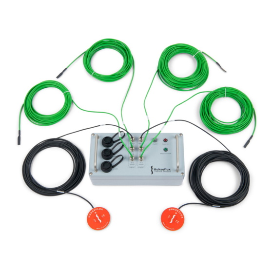
For HFP01 specifications, see the manual. HFP01 Figure 0.1 TRSYS20: the complete measuring system includes 2 HFP01 heat flux sensors and 2 matched thermocouple pairs, TC, (in total 4 temperature sensors) and the MCU measurement and control unit. On-site measurements of thermal resistance, R, are often applied in studies of buildings. - Page 6 TRSYS20, measure temperature differences with an uncertainty of better than 0.1 °C over the entire rated temperature range. TRSYS20 includes 2 x HFP01 heat flux plates. HFP01 is the world’s most popular sensor for heat flux measurement in studies of buildings.
- Page 7 This conformity assessment includes temperature difference measurement accuracy. Figure 0.3 TRSYS20 in its carrying case on the left and one HFP01 sensor on the right. 2 HFP01 heat flux sensors and 2 matched thermocouple pairs, TC, (in total 4 temperature sensors) are included in TRSYS20.
- Page 8 Standards TRSYS20 is mostly used for measurements according to standard practices of ISO 9869 and ASTM C1155 / C1046. TRSYS20 is suitable for use by ISO certified laboratories. Figure 0.4 TRSYS20 measuring system with carrying case. TR S YS 20 man u al v 2 301...
- Page 9 User interface: MCU as a web server TRSYS20 is controlled via a PC. The TPSYS20 MCU can be connected to a local area network via ethernet or directly to a PC via USB. The graphical user interface is available through a webpage and can be opened in any of the supported web browsers. No installation of software is required.
-
Page 10: Ordering And Checking At Delivery
1 Ordering and checking at delivery 1.1 Ordering TRSYS20 The standard configuration of TRSYS20 is with 2 x heat flux sensor, one with 10 and one with 20 m cable, and 2 x matched thermocouple pairs, TC, one pair with 10 m cable and one pair with 20 m cable. -
Page 11: Instrument Principle And Theory
2.1 TRSYS20 measuring system 2.1.1 HFP01 heat flux sensors TRSYS20 uses HFP01 heat flux sensors to measure the heat flux through building envelope components. Heat flux is the amount of heat flowing through a surface per unit time per unit area and is expressed in SI units of W/m HFP01 heat flux sensor contains a thermopile that generates an output voltage that is proportional to the temperature difference across the heat flux sensor. -
Page 12: Theory
To access the user interface the MCU can be connected via USB or ethernet. 2.2 Theory TRSYS20 is a system for in-situ (or field) measurements of the thermal resistance of building envelope components as opposed to ex-situ (or laboratory) measurements. - Page 13 In-situ thermal resistance evaluations use long-term averages of temperature difference across- and heat flux through the wall or building envelope component. Using the time- averaged temperature difference ΔT and time-averaged heat flux Φ the thermal resistance can be evaluated using the thermal equivalent of Ohm’s law: R = ΔT /Φ...
- Page 14 Sensors should not be exposed to rain, snow, and direct solar radiation. The standard recommends use of thermal paste. Hukseflux discourages the use of thermal paste TR S YS 20 man u al v 2 301...
- Page 15 because it tends to dry out. Silicone glue and double sided tape are more reliable. The standard recommends the use of a passive guard ring. Annex D.3.2 states that “the width of the guard ring should be at least 5 times the thickness of the heat flux meter”. HFP01 is equipped with a guard ring fulfilling the requirement of the standard.
- Page 16 TRSYS20 and HFP01 may be mounted on glass windows, however special care must be taken when interpreting data from measurements on glass. When measuring glass windows please observe the following: • During daytime, the window material typically transmits solar radiation, while the HFP01 heat flux sensors absorb this radiation.
-
Page 17: Specifications Of Trsys20
3 Specifications of TRSYS20 3.1 Specifications of TRSYS20 TRSYS20 is a system used for on-site measurement of thermal resistance, R, thermal conductance, the Λ-value, and thermal transmittance, the U-value, of building envelope components. TRSYS20 is used for measurements according to standard practices of ISO 9869 and ASTM C1155 / C1046. - Page 18 Cable markers temperature sensors location 1: TC-1 inside and TC-1 outside location 2: TC-2 inside and TC-2 outside Table 3.1.1 Specifications of TRSYS20 (started on previous page, continued on next page) Rated operating conditions Rated operating temperature range HFP01 and TC: -30 to +70 °C MCU: -20 to +50 °C...
- Page 19 Output connector type Bulgin Standard Buccaneer®, PX0736/S, 2 pole connector with sockets Ingress protection rating IP22 Table 3.1.1 Specifications of TRSYS20 (started on previous pages). HFP01 HEAT FLUX SENSOR Specifications see HFP01 manual Guard width to thickness ratio 5 (as required by ISO 9869 D.3.1) Measurement function Φ...
- Page 20 Calibration traceability HFP01, TC and MCU are traceable to SI units Calibration uncertainty HFP01 heat flux ± 3 % (k = 2) sensors Acceptance interval temperature < ± 0.1°C difference measurement (required by ISO 9869, paragraph 5.2) Recommended recalibration interval 2 yr Electromagnetic Compatibility (EMC) Emission standards...
-
Page 21: Dimensions Of Trsys20
3.2 Dimensions of TRSYS20 Figure 3.2.1 Dimensions of TRSYS20 MCU in x 10 TR S YS 20 man u al v 2 301 21/39... -
Page 22: Preparation Of An Experiment
ISO and ASTM standards. 4.1 Preparing the equipment Prior to shipping TRSYS20 system to a measurement site, the user should check that the items listed in section 1.2 are present and accounted for. Additionally, the user will need the following items not included with TRSYS20: •... -
Page 23: Trsys20 Mcu System Setup
4. Verifying the programmed HFP01 sensitivities 5.1 Setting up connection TRSYS20 is operated via a laptop or PC. TRSYS20 MCU acts as a webserver such that the user interface can be accessed using a web browser. The user interface allows the user to start and monitor measurements. -
Page 24: Setting The Clock
30 metres. 5.1.3 Logging into the TRSYS20 MCU To make sure the TRSYS20 MCU can only be controlled by the authorised users on a shared network, first time use in a new browser or PC requires the correct credentials. A pop-up will appear asking you to enter your credentials. -
Page 25: Setting The Net Frequency Filter
5.3 Setting the net frequency filter TRSYS20 uses a net frequency filter to reduce interference from power lines with the heat flux, differential temperature and temperature signals. The net frequency filter must be set for the region in which the system is used. To set the net frequency filter: in the interface select the Settings tab, in the Net frequency box select the Net frequency filter drop down list and select the net frequency for your region (e.g. -
Page 26: Installation Of Sensors: Hfp01 And Tc
(wall) that is being investigated. It is assumed that the user has completed the system setup described in chapter 5. TRSYS20 has two sets of sensors. Each set consists of a heat flux sensor, an indoor temperature sensor and an outdoor temperature sensor. - Page 27 Close window blinds and curtains Switch off artificial light sources For detailed analysis of a single building element users may consider to install one heat flux sensor indoors, and the other outdoors. Measuring on two sides permits a detailed analysis of the thermal response time. For mounting sensors on glass windows: see paragraph 4.3.1.
- Page 28 For R-value: temperature sensors should measure ambient air temperature. They are typically located close to the sensor at both sides of the wall, however not attached to the wall. Ambient air temperature sensors should be shielded from solar radiation. Avoiding spectral In case of exposure solar radiation or to artificial light sources, the errors spectral properties of the sensor surface must match those of the wall.
-
Page 29: Performing Measurements
To start the measurement, click the Start button in the Control box. The system status should change to “RUNNING”, the green indicator in the Control box should light up and the green measurement running LED on the TRSYS20 MCU should light up. -
Page 30: Retrieving Measurement Data
Typically, the two TRSYS20 sensor sets are placed on the same building envelope component to allow for a redundancy check. In that case the user should verify that the thermal resistances for the two measurement locations are comparable. Apart from monitoring the measurements via the web interface it is strongly recommended to visually inspect the sensor mounting at regular intervals during the experiment. -
Page 31: Data Analysis Tool
ISO and ASTM standards. To help the user get started with the data analysis, Hukseflux provides a data analysis tool in the form of an excel template. The data analysis tool uses the average method described in the ISO 9869-1 standard, which is similar to the summation technique described in the ASTM standard. -
Page 32: Uncertainty Evaluation
9 Uncertainty evaluation The formal evaluation of uncertainty should be performed in accordance with ISO 98-3 Guide to the Expression of Uncertainty in Measurement, GUM. 9.1 Heat flux measurements In case of heat flux sensors, the measurement uncertainty is a function of: •... -
Page 33: Maintenance And Trouble Shooting
Table 10.1.1 Recommended maintenance of TRSYS20. If possible, the data analysis is done on a daily basis. MINIMUM RECOMMENDED HEAT FLUX SENSOR MAINTENANCE... -
Page 34: Trouble Shooting
10.2 Trouble shooting Table 10.2.1 Trouble shooting for TRSYS20. The HFP01 sensor Check the programmed sensitivity in the TRSYS20 web interface. Make sure signal is incorrect, the programmed sensitivity matches the sensitivity on the calibration erratic or out of certificate. -
Page 35: Calibration And Checks In The Field
10.3 Calibration and checks in the field The recommended calibration interval of the TRSYS20 and its individual components is 2 years. Recalibration of sensors and MCU is ideally done by the sensor manufacturer. On-site performance verification is possibly by mounting heat flux sensors and thermocouple pairs side by side. -
Page 36: Appendices
11 Appendices 11.1 TRSYS20 data table Raw data can be downloaded from the TRSYS20 MCU in .csv format. The variables in the raw data file are listed in table 11.1.1. Table 11.1.1 Explanation of variables and parameters used in the HF_10min data table. -
Page 37: Eu Declaration Of Conformity
11.2 EU declaration of conformity Hukseflux Thermal Sensors B.V. Delftechpark 31 2628 XJ Delft The Netherlands hereby declare under our sole responsibility that: Product model TRSYS20 Product type High-accuracy building thermal resistance measuring system conforms with the following directive(s): 2011/65/EU, EU 2015/863... - Page 39 © 2023, Hukseflux Thermal Sensors B.V. www.hukseflux.com Hukseflux Thermal Sensors B.V. reserves the right to change specifications without notice.
Need help?
Do you have a question about the TRSYS20 and is the answer not in the manual?
Questions and answers