Table of Contents

Related Manuals for Pacbrake 10231


Summary of Contents for Pacbrake 10231
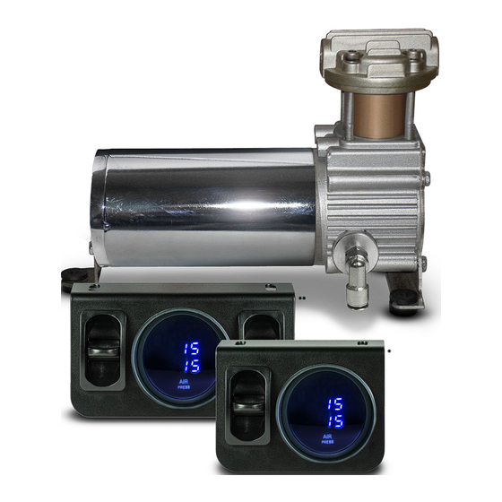
- Page 1 PREMIUM IN-CAB CONTROL KIT 325 SERIES AIR COMPRESSOR (for vehicles without a preexisting air system) 10231 SIMULTANEOUS ACTIVATION Paddle Valve w/ Digital Gauge 10256 INDEPENDENT ACTIVATION Paddle Valve w/ Digital Gauge L6393_REV6_05.14.2024...
-
Page 2: Before Starting The Installation
• Simultaneous Kits* (10231) are designed to fill and exhaust both air springs to the same pressure simultaneously. • Independent Kits (10256) are designed to fill and exhaust each air spring independently to its own pressure. - Page 3 L6393 KIT CONTENTS / LAYOUTS 10231 Kits - Ensure the kit you received contains all the items shown in Figure A. 10256 Kits - Ensure the kit you received contains all the items shown in Figure A & Figure B.
-
Page 4: Assembly Preparation
Install the check valve into the air compressor head (as shown in Figure 2A). If a simultaneous kit (10231) is being installed, install the straight tube fitting into the check valve (as shown in Figure 2A). If an independent kit (10256) is being installed, install the brass tee fitting into the check valve. - Page 5 PREMIUM In-Cab Control Kit: Simultaneous / Independent (Digital Paddle Valve) L6393 MOUNT THE RELAY RECEPTACLE Provided in the kit is a pre-wired relay receptacle. Locate it and find a convenient location to mount the relay receptacle close to the positive battery terminal. Use the provided self-tapping screw to secure the relay receptacle to the chosen location, (see Figure 3).
- Page 6 NOTE: Apply thread sealant or Teflon tape to all the fitting threads installed into the manifold to prevent air leaks. If a simultaneous kit (10231) is being installed, complete Step 5A (on the following page) and then proceed onto Step 6.
- Page 7 L6393 Simultaneous Manifold Assembly 5A SIMULTANEOUS AIR SPRING ACTIVATION MANIFOLD ASSEMBLY (10231 KITS ONLY) Install the pressure sensor into the top port of the manifold. Install two 1/8” air fittings into the side ports. Provided in the kit are five 1/8” brass plugs. Install them into the remaining ports of the manifold.
- Page 8 If a simultaneous kit (10231) is being installed, complete Step 7A (below) and then proceed to Step 8. If an independent kit (10256) is being installed, skip Step 7A, complete Step 7B (on the following page), and then proceed to Step 8.
- Page 9 PREMIUM In-Cab Control Kit: Simultaneous / Independent (Digital Paddle Valve) L6393 7B INDEPENDENT AIR SPRING ACTIVATION AIRLINE CONNECTIONS (10256 KITS ONLY) Refer to the wiring and plumbing diagram on Page 15 for the following instructions: Install both paddle switches into the supplied control panel bracket. The switches must be installed such that the delivery (DEL) port is above the supply (SUP) port.
-
Page 10: Mount The Control Panel
Option 2 (see Figure 8). 8A SIMULTANEOUS AIR SPRING ACTIVATION GAUGE HARNESS CONNECTIONS (10231 KITS ONLY) Refer to the wiring diagram on Page 14: Install the pressure gauge into the panel control bracket. Insert the supplied gauge harness into the back of it. -
Page 11: Testing The System
PREMIUM In-Cab Control Kit: Simultaneous / Independent (Digital Paddle Valve) L6393 8B INDEPENDENT AIR SPRING ACTIVATION GAUGE HARNESS CONNECTIONS (10256 KITS ONLY) Refer to the wiring diagram on Page 15: Install the pressure gauge into the panel control bracket. Insert the supplied gauge harness into the back of it. - Page 12 PREMIUM In-Cab Control Kit: Simultaneous / Independent (Digital Paddle Valve) L6393 10 CHECK SYSTEM FOR LEAKS Inflate both air springs to 90 psi (60 psi for in-coil bags) and then use a mixture of dish soap and water on all air line connections to detect any air leaks.
-
Page 13: Warranty
infl ated or compressed. Trimming off excess bolt length may also be required to ensure no contact with the spring or other suspension components can be made once installed. ▪ If removed, re-install the wheels and torque fasteners to the manufacturer’s specifi cations. Re-torque all fasteners after the PREMIUM In-Cab Control Kit: Simultaneous / Independent (Digital Paddle Valve) L6393 fi rst 500 miles of driving. - Page 14 PREMIUM In-Cab Control Kit: Simultaneous / Independent (Digital Paddle Valve) L6393 WIRING & PLUMBING DIAGRAM SIMULTANEOUS AIR SPRING ACTIVATION (10231 KITS) GREEN BLUE BROWN BROWN BLACK BLACK CONNECTOR (x3) BLACK CONNECT TO HEADLIGHT ORANGE FOR AUTO DIM (OPTIONAL) GROUND PRESS...
- Page 15 PREMIUM In-Cab Control Kit: Simultaneous / Independent (Digital Paddle Valve) L6393 WIRING & PLUMBING DIAGRAM INDEPENDENT AIR SPRING ACTIVATION (10256 KITS) BLUE BROWN BLACK CONNECTOR (x3) BLACK GREEN BROWN BLACK CONNECTOR (x3) GROUND CONNECT TO HEADLIGHT ORANGE FOR AUTO DIM (OPTIONAL) PRESS PRESS VIEW FROM FRONT...
Need help?
Do you have a question about the 10231 and is the answer not in the manual?
Questions and answers