Table of Contents
Advertisement
Quick Links
SYNTHESIZED FM
STEREO TRANSMITTER
Ramsey Electronics Model No.
Own the Hottest FM Stereo broadcast station around and play
the music you want to play! The MP3FM turns your computer
into an MP3 transmitter.
Why limit your hours worth of downloading to listening in front of
your computer, now you can enjoy the fruits of your labor from
anywhere in your home!
•
Great for transmitting your MP3 or WAV files throughout the house,
yard or even your car.
•
Fantastic audio quality; sounds better than most stations on the
dial. And we'll tell you why!
•
Enjoy PC Gaming with BOOMING sound from your stereo system.
•
Easily connects to the line or speaker level outputs on any sound
card, tape deck, stereo system, or CD player.
•
Special "loop through" design allows you to keep your computer
speakers connected; broadcast or listen directly with no rewiring.
•
Operates on 8 to 14 volts DC, 12 volt DC power supply provided.
•
Easily tunable anywhere in the 88-108 MHz FM band.
•
Clear, concise instructions guide you step-by-step to a finished
product that works FIRST time.
MP3FM
Advertisement
Table of Contents

Subscribe to Our Youtube Channel
Related Manuals for Ramsey Electronics MP3FM


Summary of Contents for Ramsey Electronics MP3FM
- Page 1 Ramsey Electronics Model No. MP3FM Own the Hottest FM Stereo broadcast station around and play the music you want to play! The MP3FM turns your computer into an MP3 transmitter. Why limit your hours worth of downloading to listening in front of...
- Page 2 COPYRIGHT 1996 by Ramsey Electronics, Inc. 793 Canning Parkway, Victor, New York 14564. All rights reserved. No portion of this publication may be copied or duplicated without the written permission of Ramsey Electronics, Inc. Printed in the United States of America. MP3FM • 2...
-
Page 3: Table Of Contents
TABLE OF CONTENTS Introduction ........4 Circuit Description ......5 Parts Layout Diagram ...... 7 MP3FM Parts List ......8 Assembly Procedure ......10 Schematic Diagram ......16 Case and Knob Assembly ....18 Choosing an Operating Frequency .. 19 Adjusting and Alignment .... -
Page 4: Introduction
MP3FM is definitely not a toy. We will refer to the FCC regulations frequently in this manual and provide you with some information necessary to enjoy the MP3FM's capabilities in accordance with the law. -
Page 5: Circuit Description
VR3 to provide us with a good clean +3 and +5 volts for the ICs. The custom FM stereo IC (U3) is the heart of the MP3FM. The control of U3 is determined by its surrounding circuitry. Potentiometers R16 and R17 allow for adjustment of the input audio levels. - Page 6 = 1/[2π (LC) ]), bringing the MP3FM’s output frequency back on frequency. If the desired frequency is higher than the reference, pin 13 is driven low. If the frequency is just right then pin 13 becomes a high impedance, basically disconnecting it from the circuit so it will cause no change in the voltage on D14.
-
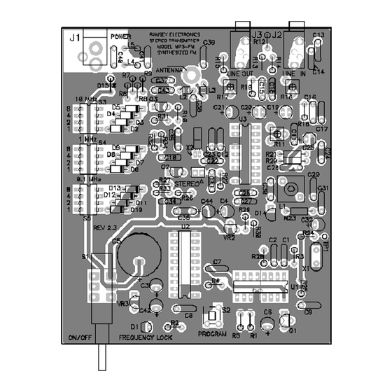
Page 7: Parts Layout Diagram
MP3FM PARTS LAYOUT DIAGRAM MP3FM • 7... - Page 8 PARTS SUPPLIED WITH MP3FM TRANSMITTER KIT Capacitors 11 .001 µF disc capacitors (marked .001, 102 or 1nF) [C12,13,14,26,29,33,35,36,40,41,43] .01 µF disc capacitors (marked .01 or 103 or 10 nF) [C8,10,17,18,30,34] .1 µF disc capacitor (marked .1 or 104 or 100 nF) [C7,9,11,31] .022 uF ceramic capacitors (marked .022 or 223) [C15,16]...
- Page 9 6 MHz crystal (thin shiny rectangle marked 6.00 or 6M000) [X1] 38 KHz crystal (small silver cylinder with two small leads), taped to paper. [X2] MP3FM printed circuit board 20 pin DIP socket (for U2) 18 pin DIP socket (for U3) 2.1mm DC power jack [J1]...
- Page 10 Since you may appreciate some "warm-up" soldering practice as well as a chance to put some "landmarks" on the MP3FM PC board, we'll first install some "hardware" components, to make the up-down, left-right orientation of the PC board as clear as possible.
- Page 11 Progress Note: The preceding steps have secured a sufficient number of components to your PC board to make general orientation around the board much clearer for installing additional parts. Further parts will be installed in six phases or groupings. MP3FM • 11...
- Page 12 6a. Install R12, a 4.7K ohm resistor (yellow-violet-red). For use in Europe, use 2.2K ohm resistors in steps 7a and 8a. These resistors set the pre-emphasis characteristic for the MP3FM. Pre-emphasis is a technique used in FM transmitters to increase the high frequency signal to noise ratio.
- Page 13 4c. Install C24, 220 pF disc capacitor (marked 220 or 221 or 220K). 5c. Install C25, 10µF electrolytic capacitor. Observe polarity. 6c. Install C26, .001 µF disc capacitor (marked .001 or 102). 7c. Install C12, a .001 µF disc capacitor (marked .001 or 102). MP3FM • 13...
- Page 14 26c. Install JMP1, a 2 pin header. A jumper block will be installed on this to enable stereo transmission. RF Amplifier 1d. Install Q2, the transistor marked C2570 (or 2498 ). The flat side must be placed as shown on the PC board, facing away from R27. Mount Q2 as MP3FM • 14...
- Page 15 7f. Install D2 - D13, small glass diodes. The banded ends go toward the center of the board, as shown on the silkscreen. 8f. Install S3, a four position DIP switch. The DIP switches are used for programming the exact transmitting frequency of your transmitter. MP3FM • 15...
- Page 16 2. Outline the holes that you need to cut using a pen or pencil. 3. Use your hobby knife or paper punch to cut the labels to their outlines. 4. Peel off the sticker backing on each sticker and place the labels over the MP3FM • 16...
-
Page 17: Choosing An Operating Frequency
FM stations can be listened to with a good system within the transmitting range of your MP3FM. This is especially important in the low end of the FM broadcast band (88-92 MHz), where there are numerous medium power National Public Radio stations. - Page 18 "hiss." Remember that if you have adjusted the MP3FM outside of 88 MHz to 108 MHz range it will default to 88.1 MHz. This means that if you can’t hear anything on the radio near the frequency you are trying to transmit at, go to 88.1 MHz and see if it is there.
- Page 19 MP3FM. Consult the literature that came with your stereo equipment. Even if you intend use of the MP3FM for your own home and family, it is still your responsibility, in accordance with Part 15 of the FCC Rules, to ensure that this operation does not cause interference to your neighbors.
-
Page 20: Troubleshooting
An interim explanation of applicable FCC regulations supplied as a personal assistance to MP3FM builders, by Dan F. Onley (K4ZRA) It is the policy of Ramsey Electronics, Inc., that knowing and observing the lawful use of all kits is a first responsibility of our kit user/builders. We do not endorse any unlawful use of any of our kits, and we try to give you as much common sense help about normal and lawful use as we can. - Page 21 In the United States, this is how the FCC regards your transmitter kit Licensed FM broadcast stations and their listeners have ALL the rights! Your use of a device such as the MP3FM kit MAY have some limited privileges in locally-unused band space, but your non-licensed use of the MP3FM has absolutely NO rights at all over the rights of licensed broadcast operators and the rights of their listeners to interference-free reception.
- Page 22 Use our AM-1 AM radio broadcast kit for this use. 6. FCC Rule No. 15.239 specifically addresses operation in the 88-108 MHz FM broadcast band for which your MP3FM transmitter kit is designed. However, this Rule does not, by itself, tell you everything you need to know about using a device of this kind.
- Page 23 "die out" at a specific distance from your antenna, no matter what kind of transmitter power or extra-gain antenna you are using. On the other hand, the FCC standards do make it legal and possible for you to broadcast on a school MP3FM • 23...
-
Page 24: Summary
The present edition of Part 15 of the FCC rules does not provide detailed guidance on ALL aspects of using a low-power transmitter such as the MP3FM. The main point is that you may not cause any interference whatsoever to licensed broadcast services and that you must be willing to put up with any interference that you may experience. - Page 25 If you become further fascinated with the service rendered by low-power broadcasting, other FCC regulations explain how to apply for a license or other authorization which may permit you to upgrade your MP3FM or other equipment to accomplish any objective which the FCC sees to be in the public interest and not interfering with other authorized uses of the radio spectrum.
- Page 26 NOTICE: The radio-frequency "intentional radiator" device which may be constructed from kit parts supplied by us is intended and designed by Ramsey Electronics, Inc. to conform to applicable provisions of Part 15 of FCC Rules. The individual kit-builder and all users of this device assume responsibility for lawful uses conforming to FCC Part 15 Rules.
- Page 27 Learn the rules...observe them...and have fun in radio! If you enjoyed this Ramsey kit, there's plenty more to choose from in our catalog - call today or visit us at www.ramseyelectronics.com! MP3FM • 27...
- Page 28 An inside view: (Keep those parts low to the board!) The Finished Product!! MP3FM • 28...
-
Page 29: Warranty
But on rare occasions a sour component can slip through. All our kit parts carry the Ramsey Electronics Warranty that they are free from defects for a full ninety (90) days from the date of purchase. Defective parts will be replaced promptly at our expense. If you suspect any part to be defective, please mail it to our factory for testing and replacement. - Page 30 SYNTHESIZED STEREO TRANSMITTER KIT Quick Reference Page Guide Introduction ........4 Circuit Description ......5 Parts Layout Diagram ...... 7 MP3FM Parts List ......8 Assembly Procedure ......10 Schematic Diagram ......16 Troubleshooting ....... 22 FCC Rules and Information ..... 22 Understanding Field Strength ..
Need help?
Do you have a question about the MP3FM and is the answer not in the manual?
Questions and answers