Advertisement
Quick Links
INSTRUCTION MANUAL
IM391-U v0.7
EMM-µD3m-TT
EMM-µD3m-485-TT
DIGITAL MULTIFUNCTION METER FOR ELECTRICAL PARAMETERS
GENERAL
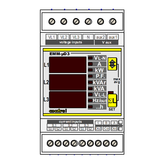
The digital multimeters series EMM-µD3m allow monitoring the main electrical parameters
present on a distribution line. The local display of the various electrical parameters is carried out
by 3 displays with red LED, granting a good and simultaneous reading of various values. A
simple front panel completes the intuitive selection of several electrical parameters, in order to
provide full information.
This instruments have a active energy counter for each phase (three single phase energy
counters), separated for positive (exported) and negative (imported) plus the counters for
system energy active (exported / imported) and reactive.
These instruments store and display several parameters (see table STORED VALUES (max/max-avg
PARAMETERS section.
The multifunction meters EMM replace in a unique device, all the functions of voltmeters, ammeters, energy meters,
cosphimeters, wattmeter's, varmeters, hour meters and frequency meters. This gives a great economic saving, by reducing
space and time, optimising also the purchase management of instruments, since one model meets most demanding
requirements for local measuring in electrical boards, switch-boards, MCC's, Gen-sets, etc.
AVAILABLE TYPES
Among the large range of the EMM multimeters family, find here below the available EMM-µD3m-TT types:
EMM-µD3m-TT
base version.
EMM-µD3m-485-TT
as EMM-µD3m-TT but with RS485 port.
The auxiliary supply for all types, is available with following voltages:
- 230V (rated) 50-60Hz
- 110V (rated) 50-60Hz
- 400V (rated) 50-60Hz
OPTIONS
Options: Auxiliary supply and measuring voltages, other than standard (under request)
TT or TTA current sensors to choose between available models
INTRODUCTION
The auxiliary supply is connected to 2 terminals, separated from the measuring voltage inputs.
The current inputs are fitted only for TT-sensors series.
No other types of transducers or CT can be connected to the current inputs of this instruments. The multimeter is
shipped with current inputs configured for the TT-sensor and cannot be changed by the user.
All types can be set to have energy counters operating in two modes:
- Bidirectional counters mode, with energy counters to count imported and exported active energy
(
/
- Total / partial counters mode, with energy totalize and resettable counters; in this mode ONLY the exported energy is
counted
(
/
EMM-µD3m-TT
EMM-µD3m-485-TT
standard version
optional version
optional version
/
)
/
)
instruction manual
)
) into MEASURED
IM391-U v0.7
pag. 1 / 12
Advertisement

Subscribe to Our Youtube Channel
Related Manuals for Contrel EMM-mD3m-TT


Summary of Contents for Contrel EMM-mD3m-TT
- Page 1 INSTRUCTION MANUAL IM391-U v0.7 EMM-µD3m-TT EMM-µD3m-485-TT DIGITAL MULTIFUNCTION METER FOR ELECTRICAL PARAMETERS GENERAL The digital multimeters series EMM-µD3m allow monitoring the main electrical parameters present on a distribution line. The local display of the various electrical parameters is carried out by 3 displays with red LED, granting a good and simultaneous reading of various values.
-
Page 2: Measured Parameters
MEASURED PARAMETERS Parameters Measuring units Identification symbols ISTANTANEOUS VALUES V phase and three phase voltage L1-N L2-N L3-N V phase to phase and three phase system voltages L1-L2 L2-L3 L3-L1 I phase and three phase currents PF phase and three phase power factors PF L1 W... - Page 3 5 A serial port Contrel sensor TT series and only the type fitted in the shipped instrument. Use of different type of sensors or CT can produce damage for the instrument and danger for the users. Wires leadings primary currents MUST be insulated type and with adequate insulation to the line voltage. The instrument’s SETUP menu allows to set the transformation rate adequate to the sensor (see Table TT-sensor ratios) and...
-
Page 4: Wiring Diagrams
WIRING DIAGRAMS WIRING IN A THREE PHASE LINE WITH 3 OR 4 WIRES aux1 auxiliary supply aux2 LOAD On three wires line (without neutral or with not distribuited neutral) DON’T wire the N terminal. RS485 Connection Connection with shielded Connection with not shielded aux1 aux1 aux2... - Page 5 DESCRIPTION: LEGEND: Key for visualising the three phase system parameters with its corresponding LED. By pressing again this key, the instrument returns to reading each individual phase. By keeping the key pressed for 5 seconds the instrument reaches the programming mode (SETUP). In SETUP mode, this key confirms the values set and by pressing the B key simultaneously, it voltage inputs...
- Page 6 CONFIGURATION OF GENERAL PARAMETERS ( Entry to menu: Increase Set CT ratio from Decrease Increase Set VT ratio from Decrease Increase Set average time from minutes Decrease Set energy counters mode Set wiring connection type Set synchronism type (only for EMM-µD3h-485) Increase Set address of network from...
- Page 7 Use of key in Setup The A key is used to ENTER into an item menu, CONFIRM and ADVANCE to next setup when modifying the parameters. When modifying the parameter, to increase the value press the B key, to decrease it, keep hold the B key and then press the A key. To speed up the operation to increase or decrease, keep on pressing the button(s) and the variation will appear successively by tens and hundreds, releasing and pressing the key again it will return to increase or decrease the value at unit per unit.
- Page 8 CANCELLING OF THE PEAK VALUES AND ENERGY METERS ( From the measures visualisation mode, keep the A key pressed until the message appears on the C display; then press the B key until the message appears on the C display; access to the reset menu by pressing the A key.
- Page 9 MEASURES VISUALISATION According with the glowing status of the G LED the reading of the measures is visualised on display C, either the three measures of the phase values or the three phase measured values (average of the individual phases for voltage, current, power factor and the sum of the individual phases for powers).
- Page 10 SINGLE PHASE PAGES FOR ENERGY COUNTERS Visualization page 9 Visualization page 10 Visualization page 11 Active Energy imported Active Energy imported Active Energy imported (POSitive Active energy) (POSitive Active energy) (POSitive Active energy) L1 phase : 232,8 kWhr L2 phase : 154,8 kWhr L3 phase : 123,3 kWhr L L...
- Page 11 VISUALIZATION OF THE THREE PHASE ISTANTANEOUS VALUES Visualization page 1 Visualization page 2 Visualization page 3 VL-N on L1 PF VL-L on L1 Freq. on L2 on L2 kVAr on L2 on L3 kVA on L3 EMM-µD3 EMM-µD3 EMM-µD3...
- Page 12 TECHNICAL CHARACTERISTICS MEASURES AND ACCURACY Voltage True rms value of the phases voltages and phase to phase in a three phase system Total range of measure: 20÷500V trms phase to phase- 380V rms phase-neutral – 40÷100Hz Visualization (20,0÷500V) - measure accuracy: ±0,5% ±1 digit – maximum values management Current True rms value of phase currents and three phase system value Range of measure: 0,02÷5A trms digit –...
Need help?
Do you have a question about the EMM-mD3m-TT and is the answer not in the manual?
Questions and answers