Advertisement
Quick Links
INSTRUCTION MANUAL
IM425-U v3.1
EMM-R3-VA
EMM-µ3-VA
MULTIFUNCTION VOLT/AMMETER
GENERAL
The digital Multifunction Volt/Ammeter series EMM-VA allow monitoring the
main electrical parameters present on a distribution line. The local display of
the electrical parameters is being made through 3 display with red LED,
which grant a good and simultaneous reading of various measures. The
intuitive selection of the measures to visualise, which are signalled by their
corresponding LED, completes a clear and simple front panel, which offer a
lot of useful information.
On top of the instantaneous measuring, these instruments visualise the
maximum peak of the main parameters (maximum peak and maximum
demand or maximum average value).
Multifunction Volt/Ammeter series EMM-VA replace, in an unique device, all
the functions of voltmeters, ammeters and frequency meters, permitting a
great economic saving, due to reducing of dimension and wiring, so as
optimising the instruments management, since one has most of all in one, for
electrical boards, switch-boards and Gen-Sets.
AVAILABLE MODELS
EMM-R3-VA
EMM-µ3-VA
ACCESSORI ED OPZIONI
accessories: transparent cover for frontal protection.
options: C1
auxiliary power supply 230 V
C2
auxiliary power supply 115 V
1A
current inputs for CT ../1Amp.
T
current inputs with galvanic insulation (not for direct connection line insertion)
P
n.2 digital output alarm signal (Photomos ca/cc).
INTRODUCTION
The EMM-R3-VA and EMM-µ3-VA models are only featured for visualising the electrical parameters. The power supply is
taken from the measured voltage or self-supplied.
MESURED PARAMETERS
Parameters
Phase and three phase voltage
Phase to phase and three phase system voltages
Phase and three phase currents
Frequency
Hour meter
STORED PARAMETERS
Instantaneous Values:
Maximum phase voltage
Minimum phase voltage
Maximum phase to phase voltage
Maximum phase current
Measured value in 15'
Average phase current (maximum demand)
checks
EMM-R3-VA
EMM-μ3VA
Measuring units
[V-kV]
V
[V-kV]
V
[A-kA]
I
[Hz]
Hz
[hr]
hr1
[V-kV]
V
[V-kV]
V
[V-kV]
V
[A-kA]
I
[A-kA]
I
instruction manual
Identification Symbols
V
L1-N
L2-N
V
L1-L2
L2-L3
I
L1
L2
L1
hr2
V
L1-N max
L2-N max
V
L1-N min
L2-N min
V
L1-L2 max
L2-L3 max
I
L1 max
L2 max
I
L1 max (avg)
L2 max (avg)
Check phase rotation
IM425-U v3.1
V
L3-N
V
L-N
V
L3-L1
V
L-L
I
L3
I
hr3
V
L3-N max
V
L3-N min
V
L3-L1 max
I
L3 max
I
L3 max (avg)
pag. 1
Advertisement

Related Manuals for Contrel EMM-m3-VA


Summary of Contents for Contrel EMM-m3-VA
- Page 1 INSTRUCTION MANUAL IM425-U v3.1 EMM-R3-VA EMM-µ3-VA MULTIFUNCTION VOLT/AMMETER GENERAL The digital Multifunction Volt/Ammeter series EMM-VA allow monitoring the main electrical parameters present on a distribution line. The local display of the electrical parameters is being made through 3 display with red LED, which grant a good and simultaneous reading of various measures.
- Page 2 INSTALLATION WARNING FOR THE USER Read carefully the instructions/indications contained in this manual before installing and using the instrument. The instrument described in this manual is intended for use by properly trained staff only. SAFETY This instrument has been manufactured and tested in compliance with EN 61010-1 standards. In order to maintain these conditions and to ensure safe operation, the person must comply with the indications and markings contained in the manual.
-
Page 3: Wiring Diagram
WIRING DIAGRAM INSERTION ON THREE-PHASE LINE WITH 3 or 4 WIRES On line with 3 wires (without neutral or with neutral not supplied) the N terminal must not be connected LOAD INSERTION ON THREE PHASE LINE WITH 4 WIRES WITH 3 TV LOAD EMM-R3-VA EMM-μ3VA... - Page 4 CURRENT INSERTION ON THREE PHASE LINE WITH 2 CT (insertion AARON) LOAD VOLTAGE INSERTION ON THREE PHASE LINE WITH 3 WIRES WITH 2 VT This insertion is possible only with the internal CT version (-t suffix). LOAD EMM-R3-VA EMM-μ3VA instruction manual IM425-U v3.1 pag.
- Page 5 INSERTION ON BALANCED THREE PHASE LINE WITH 3 or 4 WIRES On line with 3 wires (without neutral or with neutral not supplied) the N terminal must not be connected LOAD INSERTION ON SINGLE PHASE LINE Only for model with phase-neutral power supply (Vaux L3-N) LOAD EMM-R3-VA...
-
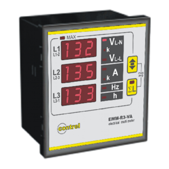
Page 6: Front Panel Description
FRONT PANEL DESCRIPTION L1-2 L1-2 L1-2 L2-3 L2-3 L2-3 L L L L3-1 L3-1 L3-1 electrical multi meter electrical multi meter electrical multi meter DESCRIPTION: Push-button for visualising of the three phase system parameters with the corresponding indication LED. By pressing during 5 seconds, user accedes to programming the instrument (SETUP). Push-button for selecting the measures to visualise on display E. - Page 7 MENU OF INSTRUMENT PROGRAMMING (SETUP) After the connecting the power supply to the instrument and waiting few seconds (all LED’s will glow and the first indication of the firmware appears on the display and all segments will glow later), press and keep pressing the key A during 5 seconds, when the message seT UP will appear on the display E.
- Page 8 - Programming of the transformation ratio of the external voltage transformers After the precedent programming phase, on E display will appear the inscription VT (voltage transformer) and the value of the transformation rate of the external TV (set to 1 from the constructor), considered as the rate between primary and secondary (example with TV 15/0.1 kV the value will be 150).
- Page 9 PROGRAMMING OF THE DIGITAL OUTPUT (SET DO1 SET DO2) This setting is enabled only in the model with digital outputs (-p suffix in the order). The DO1 and DO2 digital outputs can be used to signal alarms (ALR) using a comparing with two adjustable threshold for each output.
- Page 10 SET THE DELAY TO THE DIGITAL OUTPUT ACTIVATION Now it’s possible to set the delay that will pass between the alarm condition set and the activation of digital output. On E display will appear ALR DLY and the value expressed in seconds (range 1÷900). The modification of the value is done in the same way of the threshold set.
- Page 11 PROGRAMMING OF THE HOURS COUNTER (SET HR_) The hour counter will be increased when the measure of the parameter will exceed the set threshold value. The threshold set is applied to the system value of the parameter selected. For the frequency the referring it’s the same to the measure of the L3 phase.
- Page 12 MEASURES VISUALISATION The measures reading is visualised on the display E, showing the three phase measures (L1, L2 y L3 respectively) of the indicated parameter by the C LED. For measuring the phase to phase voltage (V ), the three measures are understood L1-L2 L2-L3 L3-L1 respectively, as indicated on the front plate.
- Page 13 Visualizations parameter of system (LED L on), L L EMM-R3-VA EMM-R3-VA [7] Visualization measure of system [8] Visualization measure OF system L1: AVERAGE PHASE VOLTAGE L1: AVERAGE PHASE TO PHASE VOLTAGE L2: AVERAGE PHASE CURRENT L2: AVERAGE PHASE CURRENT L3: FREQUENCY L3: FREQUENCY In balanced three phase system mode (BALANC) are available only the visualization [7] and [8]: In single phase mode (!PH L3) the pages displayed are the following:...
- Page 14 VISUALISING THE INSTANTANEOUS AND AVERAGE PEAK (MAXIMUM) VALUES By pressing the A and B keys simultaneously, the instrument enters into the visualisation of the peak (maximum) values: The LED D will glow. The memorised peak (maximum) values, which might be selected by the B key, will be shown on the display E.
-
Page 15: Technical Characteristics
TECHNICAL CHARACTERISTICS MEASURES, ACCURACY Voltage True rms for the phase, phase to phase and three-phase voltage Total measuring range: 20÷500V trms phase-phase - 290V rms phase-neutral, depending always to the power supply voltage. Visualization (0,02÷50,0kV) – measuring accuracy: ±0,5% ±1 digit Current True rms for the phase and three-phase currents. - Page 16 L L3-1 electrical multi meter Drill panel L1-2 L1-2 L2-3 L2-3 L L EMM-µ3-VA L3-1 L3-1 electrical multi meter electrical multi meter For other applications, please contact with CONTREL technical assistance department. EMM-R3-VA EMM-μ3VA instruction manual IM425-U v3.1 pag. 16...
Need help?
Do you have a question about the EMM-m3-VA and is the answer not in the manual?
Questions and answers