Table of Contents

Subscribe to Our Youtube Channel
Related Manuals for Contrel EMA11


Summary of Contents for Contrel EMA11
- Page 1 EMA11 LECTRICAL ULTIFUNCTION NALYZER LECTRICAL ULTIFUNCTION NALIZER ECORDER LECTRICAL ULTIFUNCTION NALIZER ECORDER P. D ELECT ELECT NTER User Manual IM 135-U v. 4.1 EMA11 IM135-U v4.1.doc...
- Page 2 The information contained herein is the property of Contrel Elettronica Srl, and by law, no part of it may be reproduced, transcribed, stored in any retrieval system, or translated into any language by means (even for internal purposes by the customer) without the express written permission of Contrel Elettronica Srl.
-
Page 3: Table Of Contents
EMA11 - USER MANUAL INDEX MAIN INFORMATION________________________________________________________5 1.1) INTRODUCTION _________________________________________________________5 1.2) DESCRIPTION ___________________________________________________________5 1.3) CE CONFORMITY AND STANDARDS ________________________________________5 TECHNICAL FEATURES _____________________________________________________6 2.1) GENERAL SPECIFICATIONS_______________________________________________6 2.2) MEASURING METHOD AND ACCURACY_____________________________________8 2.3) PROGRAMMABLE PARAMETERS (SETUP SECTION) __________________________8 2.4) MEASURED VARIABLES __________________________________________________9 2.5) - Page 4 EMA11 - USER MANUAL 8.3.3) 4 STATIC DIGITAL OUTPUTS OPTION 4DO (“PLUG IN”)_____________________24 8.3.4) 4 RELAY DIGITAL OUTPUTS OPTION 4DO (“PLUG IN”) _____________________24 8.3.5) 2 ANALOG OUTPUTS OPTION 2AO (“PLUG IN”) ___________________________24 8.3.6) 4 ANALOG OUTPUTS OPTION 4AO (“PLUG IN”) ___________________________25 8.4)
-
Page 5: Main Information
1.2) DESCRIPTION The EMA11 is an instrument which has been designed to monitor, store and analyze all electrical variable in a distribution line. All the relevant data are displayed and, if desired, stored on internal RAM and transmitted to a remote PC, via RS485 (standard) on which the compatible management software has been installed. -
Page 6: Technical Features
EMA11 - USER MANUAL TECHNICAL FEATURES 2.1) GENERAL SPECIFICATIONS Power supply/Auxiliary voltage 85-265 V 50/60 Hz/dc. 20-60 V 50/60 Hz/dc (option). Isolation voltage 3700 Vac rms x 1 minute. Voltage input 3 inputs, range 10-600Vrms between phase-phase. Over voltage up to 750 Vac permanent, beyond this value it is imperative to use voltage transformers. - Page 7 EMA11 - USER MANUAL Operating temperature From -10°C (14°F) to +50°C (122°F). Storage temperature From -15°C (5°F) to +70°C (158°F). Operating humidity 90% not condensing. Protection standards IP 52 front (EN60529) - IP65 with gasket (on request). IP 20 screw and terminals.
-
Page 8: Measuring Method And Accuracy
EMA11 - USER MANUAL 2.2) MEASURING METHOD AND ACCURACY Measuring range 30-500Hz. Measuring method 64 sampling per period for V1 and I1, V2 and I2, V3 and I3. Measuring interval 0,1 second. Instrument accuracy Model EMA11 Model EMA11-05 Voltage < 0.5 % <... -
Page 9: Measured Variables
EMA11 - USER MANUAL 2.4) MEASURED VARIABLES PHASE VOLTAGE (Rms) L1-N L2-N L3-N LINE CURRENT (Rms) FREQUENCY (Hz) TEMPERATURE T(°C) 2.5) CALCULATED VARIABLES LINE VOLTAGE (Rms) L1-L2 L2-L3 L3-L1 THREE-PHASE SYSTEM VOLTAGE (Rms) THREE-PHASE SYSTEM CURRENT (Rms) AVERAGE THREE-PHASE SYSTEM CURRENT... -
Page 10: Measuring & Calculation Formulas
EMA11 - USER MANUAL 2.6) MEASURING & CALCULATION FORMULAS ∑ L iN k Phase Voltage V L iN ∑ L iN k Line Current I L i ⋅ ∑ iN k Active Power W L i ⋅ ∑ − iN k ∆... - Page 11 EMA11 - USER MANUAL ∞ Reactive Energy ∫ ∑ L ij k Line Voltage V L ij Phase Line Voltage V Φ Phase System Current I Φ Phase Active Power W Φ Phase Reactive Power Q Φ PhaseAppea rent A Φ...
-
Page 12: Instrument Description
EMA11 - USER MANUAL INSTRUMENT DESCRIPTION The front panel of the EMA11 is described on the following section: 1 DISPLAY Back lighted graphic LCD 70x70mm, 128x128 dot, dot pitch 0.35mm x 0.35mm, dot size 0.32mmx0.32mm, high viewing direction 60°, positive and negative visualization at low reflection. -
Page 13: Installation
EMA11 - USER MANUAL INSTALLATION 4.1) SAFETY On receipt of the instrument and prior to installation, make sure it is intact and has not been damaged during shipment. Before installing, make sure the operating voltage and mains voltage are compatible. -
Page 14: Mounting
EMA11 - USER MANUAL 4.3) MOUNTING The unit needs to be installed on front panel of mains control/switchboards, wiring and connections must be carried out following the EMC (Electro-Magnetic-Compatibility) procedures. Plug in screw terminal blocks are used for appropriate wiring. There is a security locking on the current inputs terminal block. -
Page 15: Internal Battery
EMA11 - USER MANUAL INTERNAL BATTERY To avoid to lose the setup and all storing data, the instrument is equipped of an internal battery (CR2450). 5.1) REPLACEMENT INTERNAL BATTERY Only a qualified and authorized technical person can change the internal battery. -
Page 16: Connection
EMA11 - USER MANUAL CONNECTION Aux2 (-) Connection Table Connector Name Connector Name TX/A (ser.output) 2 Digital Input (+) RX/B (ser.output) 2 Digital Input (-) COM (ser.output) 1 Digital Output (+) 1 Digital Output (-) 1 Digital Input (+) 2 Digital Output (+) -
Page 17: Voltage Inputs
Connect the instrument following up the wiring diagrams described on chapter 6.4). EMA11 was developed and tested in accordance with IEC 348 class 1 standards for operating voltages up to 600 Vac rms. 6.3) CURRENT INPUTS Connect the instrument following up the wiring diagrams described on chapter 6.4). - Page 18 EMA11 - USER MANUAL 4 wires insertion, 3 current transformers and 3 voltage transformes 4 wires insertion, 3 current transformers Single fase insertion, 1 current transformer 4 wires insertion, 3 current transformers and 2 voltage transformers -18-...
-
Page 19: Plug-In Module Insertion
EMA11 - USER MANUAL PLUG-IN MODULE INSERTION See the following picture to insert the plug-in module: It’s only possible to see the two slots, shown in the picture, when the rear door is removed. To remove the rear door it’s necessary to act, in the zone indicated of the arrow, on the retention lever. -
Page 20: Insertion Procedure
EMA11 - USER MANUAL 7.1) INSERTION PROCEDURE Only a qualified and authorized technical person can insert the plug-in module. Follow this procedure to operate in the maximum security: 1) Cut off the power supply of instrument and disconnect all inputs and all outputs. -
Page 21: Input/ Output Devices
For the digital input setup please consult the chapter 11.9). If long distances must be covered, the wires connected to the EMA11 needs to be wired in a separate channel from the power supply cables, if an intersection occurs between the power supply cable and the analog wires, please remember to cross the intersection at 90 degrees, in order to cut the generated magnetic fields. -
Page 22: Standard Digital Outputs
The signs + and - on outputs in the picture have electric meaningless. If long distances must be covered, the wires connected to the EMA11 needs to be wired in a separate channel from the power supply cables, if an intersection occurs between the power supply cable and the analog wires, please remember to cross the intersection at 90 degrees, in order to cut the generated magnetic fields. -
Page 23: Input / Output Options ("Plug In" Module)
EMA11 - USER MANUAL 8.3) INPUT / OUTPUT OPTIONS (“PLUG IN” MODULE) It’s possible to use this following plug-in module option: a) 6 digital inputs (6DI) b) 2 digital inputs + 2 digital outputs (2DI+2DO) c) 4 static digital outputs (4DO) -
Page 24: 3) 4 Static Digital Outputs Option 4Do ("Plug In")
150Ω 150Ω If long distances must be covered, the wires connected to the EMA11 needs to be wired in a separate channel from the power supply cables, if an intersection occurs between the power supply cable and the analog wires, please remember to cross the intersection at 90 degrees, in order to cut the generated magnetic fields. -
Page 25: 6) 4 Analog Outputs Option 4Ao ("Plug In")
EMA11 - USER MANUAL The EMA11 gives a current signal (range 4÷20mA or 0÷20mA) proportional to the measures of the selected parameter. The output is bi-directional: the current can be directly or inversely proportional to reference value programmed. Bi-directional means reversal of reference value and not inversion of current. -
Page 26: Serial Outputs
EMA11 - USER MANUAL 8.4) SERIAL OUTPUTS Through the combination of an asynchronous serial RS485 and RS232 communication line it is possible to exchange information between the instrument and PC, PLC or other compatible systems. All transmitted characters are in ASCII (American Standard Code for Information Interchange) format. -
Page 27: 2) Rs485 Connection Shielded
EMA11 - USER MANUAL 8.4.2) RS485 CONNECTION SHIELDED RS232 Max 32 EMA; max 1200 mt RS232/RS485 converter EMA 11 EMA 11 Although the signal is given by the difference between A and B voltage, a ground connection is needed to eliminate or to reduce the common mode noise induced (into the bus). -
Page 28: 4) Modem Connection
EMA11 - USER MANUAL 8.4.4) MODEM CONNECTION It’s possible to manage the supervisioning of energy consumption through remote structures as modem application in order to cover big distances. Signal Transmit Data Receive Data Signal GrouND To make the remote connection it needs to program the remote modem (connected to the EMA network). -
Page 29: 5) Option Rs485/Rs232 Com2 ("Plug-In")
EMA11 - USER MANUAL 8.4.5) OPTION RS485/RS232 COM2 (“PLUG-IN”) Modem Personal Computer RS485 / RS232 Warning. The hardware modification of instrument will change the Setup in the default configuration. -29-... -
Page 30: Use
EMA11 - USER MANUAL 9.1) FUNCTION KEYS • UP & DOWN KEYS The “UP” and “DOWN” keys allows to skip through the real time pages and to select the programming level or to modify values during the input in the setup menu. -
Page 31: Visualization Tree
EMA11 - USER MANUAL 10.1) VISUALIZATION TREE 3 - Phase L1 Phase L2 Phase L3 Phase System L1 Phase V-C L2 Phase V-C L3 Phase V-C Phase Voltage Line Voltage Avg Current Line Current Avg Current Thd Voltage Thd Current... -
Page 32: Measures Visualization
EMA11 - USER MANUAL 10.2) MEASURES VISUALIZATION Variable reading of three - phase system • (V - kV) RMS three - phase system voltage [∑ V • (A - kA) RMS three - phase system current [∑I] • (W - kW - MW - GW) three - phase system active power [Σ W] •... - Page 33 EMA11 - USER MANUAL Voltage and current wave forms L2 line In the “L2 Phase V-C” page are showed the voltage and current wave forms with their peak values and crest factors. The wave form of the current has the lower amplitude.
- Page 34 EMA11 - USER MANUAL Variable reading average line, three-phase system and neutral current • (A - kA) rms average three - phase system current [Σ I • (A - kA) rms average current L1 phase [I • (A - kA) rms average current L2 phase [I •...
- Page 35 EMA11 - USER MANUAL Variable reading three-phase powers • (W - kW - MW - GW) three - phase system active power [ΣP] • (VAr - kVAr - MVAr - GVAr) three - phase system reactive power [ΣQ] • (VA - kVA - MVA - GVA) three - phase system apparent power [ΣS] •...
- Page 36 EMA11 - USER MANUAL Variable reading phase power factor • (P.F.) three phase system power factor [ΣPF] • (P.F.) power factor L1 [PF • (P.F.) power factor L2 [PF • (P.F.) power factor L3 [PF Variable reading phase cosϕ • (cosϕ) three phase system cosϕ [Σcosϕ] •...
- Page 37 EMA11 - USER MANUAL Variable reading counters This page shows the 8 counters available. Note: These pages appeared only if the digital inputs are set like COUNTERS. Variable reading consumption of active and reactive energy (Normal) • (kWh) positive active energy counter [kWh+] •...
- Page 38 EMA11 - USER MANUAL Variable reading time-band energy counters (option) 20 pages to display the active energy counters (positive and negative) and reactive (capacitive and inductive) divided in 4 programmable time bands (P1 - P2 - P3 - P4). The 20 pages are: consumption present year and the...
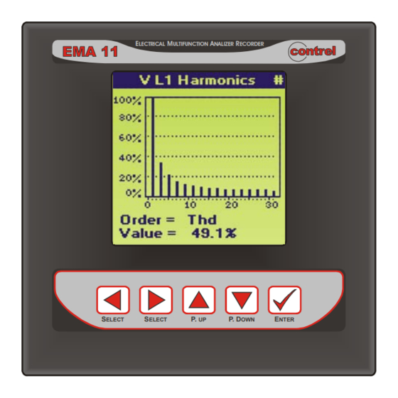
- Page 39 EMA11 - USER MANUAL Variable reading Thd of voltage and current (harmonics orders option) A page shows the total harmonic distortion of voltage and of current: • (Thd) total harmonic distortion of voltage L1 phase [Thd • (Thd) total harmonic distortion of voltage L2 phase [Thd •...
-
Page 40: Status And Information Pages
EMA11 - USER MANUAL 10.3) STATUS AND INFORMATION PAGES The status and/or information pages include: • the displaying of clock and internal calendar • the condition of internal RAM memory • the condition of digital I/O • warnings • general info of the instrument Clock/Calendar •... - Page 41 EMA11 - USER MANUAL Warnings To see “warnings” are available 2 pages. The first page shows the situation of the connection of the instrument, regarding the connection of current transformer in the current input and the phase sequence for the voltage input. If at least one of current transformer is inverted, the display shows “Warning TA”, otherwise “TA OK”.
-
Page 42: Setup
EMA11 - USER MANUAL SETUP 11.1) SETUP ITEMS GENERAL HOLIDAYS Day Index (1÷40) KCT-Pri. (1÷5000) Month (1÷12) KCT-Sec. (1;5) Day (1÷31) STORAGE KVT-Pri. (1÷400000) MIN MAX KVT-Sec. (1÷750) Enable (On-Off) Mode (4 wires -3 wires -Aron) Measures (list of parameters) Rate-min. -
Page 43: Main Menu Setup
EMA11 - USER MANUAL 11.2) MAIN MENU SETUP The main menu or SETUP page is configured in the following way: • GENERAL, includes the settings of KCT (current ratio), KTV (voltage ratio), MODE (4 wires, 3 wires, Aron), MEASURE TIME (time constant of measure filter), WARNINGS, B.LIGHT (Backlit on display timing),... -
Page 44: General
CT, if it’s used, in order to show the measured values in primary terms. Primary Range: 1÷5000A; Secondary Range: 1 or 5A (for EMA11-1A is fixed to 1). I.e. Set KCT-Pri.=200 and KCT- Sec.=1 if a CT used is an 200/1 A. -
Page 45: Serial Comm
EMA11 - USER MANUAL 11.4) SERIAL COMM The SERIAL COMM menu allows the programming of the communication parameters of the COM1 and the option COM2. • Protocol, can be chosen between ASCII and MODBUS. • Address, is the address, node or logic number from 01 to 255 in MODBUS or from 01 to 128 in ASCII. -
Page 46: Energy
EMA11 - USER MANUAL 11.6) ENERGY In the ENERGY menu it’s possible to modify the unit of measurement of energies, to set at the initial value the generic and energy counters, to manage on the time-bands. • Type, allows to choose the unit of measurement for the energy counter kWh (Normal) or MWh (Heavy). - Page 47 EMA11 - USER MANUAL WeekDay, defines the days of the week in the selected period in which the tariff programming is active. Use the “LEFT” and “RIGHT” keys to select the day of the week and the “UP” and “DOWN” keys to enable or disable the day.
-
Page 48: Storage
EMA11 - USER MANUAL 11.7) STORAGE The STORAGE menu allows the programming of the data to store. 4 archives of storing exist: - relative minimums and maximums - average powers - harmonic components - samples (only with NRG software or serial command) The storage is organized as FIFO (first in first out) type memory. - Page 49 EMA11 - USER MANUAL • TRIGGER Enable, the operator may enable or disable the TRIGGER function. If Enable is OFF the enabled archives store the measures with the relative rate, all of time. If Enable is ON, the enabled archives store the measures with the relative rate only after the receiving pulse on digital input 2 (DI2).
-
Page 50: Digital Output
EMA11 - USER MANUAL 11.8) DIGITAL OUTPUT The digital outputs can be programmed to function like alarm (overload, load management for consumption optimization, etc.), or pulses emission for energy calculation or remote activation using software NRG. • Out Index, expresses the number of output, from 1 to 6 (DO1 and DO2 standard), to select or program, which are present on the hardware of the instrument. -
Page 51: Digital Input
EMA11 - USER MANUAL 11.9) DIGITAL INPUT In the DIGITAL INPUT menu it’s possible to program the digital input function for both standards and options. The 2 standards digital input can be programmed how follow: • Type, defines the type of operation: - NOT USED: if none input is selected or enabled. - Page 52 EMA11 - USER MANUAL An item selected in the menu “TYPE” of the digital inputs will be accepted only if the reset of the counters is confirmed. • Count. => Input, define the correspondence between the index of the counter and the digital input. It’s necessary to set the index of the digital input to join at each counter used.
-
Page 53: Analog Output (Option)
EMA11 - USER MANUAL 11.10) ANALOG OUTPUT (OPTION) Selecting the analog output voice, the following programming page appears: • Out Index, expresses the number of output to select or program, which are present on the hardware of the instrument. • Type, allows to select the value of current output, (disabled, 0-20mA, 4- 20mA). -
Page 54: Reset
EMA11 - USER MANUAL 11.11) RESET The Reset page allows to cancel some operation or the complete operation of the setup system, reset modes are classified in four groups. RESET MEASURES, reset all values or selected group of measure. In particular: •... - Page 55 EMA11 - USER MANUAL 3 Ph.Cos Three-phase CosΦ L1 Cos L1 phase CosΦ L2 Cos L2 phase CosΦ L3 Cos L3 phase CosΦ 3Ph.VA Three-phase apparent power L1 VA L1 phase apparent power L2 VA L2 phase apparent power L3 VA L3 phase apparent power 3Ph.W...
-
Page 56: Problems And Solutions
EMA11 - USER MANUAL PROBLEMS AND SOLUTIONS If you have a problem setting up or using your instrument, you may be able to solve it yourself. Before calling your retailer or nearest distributor you should try the suggested actions that are appropriate to your problem. -
Page 57: Ema Serial Communication Protocol
About all the information of protocols communication to see specific user manual (EMA SERIAL COMMUNICATION PROTOCOL). Notes WARNING: Contrel Elettronica Srl declines all liability for any damage to people or property caused by improper or incorrect use of its products. Contrel Elettronica Srl reserves the right to change product specifications without prior notice. - Page 58 EMA11 - USER MANUAL -58-...
Need help?
Do you have a question about the EMA11 and is the answer not in the manual?
Questions and answers