Table of Contents
Advertisement
Quick Links
26900 LODI - ITALY -
Tel. ++39(0)371 30207/30761
INSTALLATION
OPERATOR SAFETY
Read carefully the instructions contained in this manual before installing and utilising the instrument.
The instrument described in this manual / in the following manual is intended for use by properly trained staff only
SAFETY
This instrument was manufactured and tested in compliance with IEC 1010 standards. In order to maintain these conditions and to ensure safe operation,
the personnel must comply with the indications and markings contained in the following manual.
When the instrument is received, before beginning installation, check that it's still intact and no damage was incurred during transport.
Before installing / before beginning installation make sure that the operating voltage and mains voltage are compatible with the device instructions. The
instrument power supply must not be earthed. Maintenance and/or repair must be carried out only by qualified and authorized personnel. If there is ever the
suspicious that, during the operation phase. that safe is no longer possible, the instrument must be taken out of service and precautions taken against
accidental use.
-Operation is no longer safe when:
•
The instrument no longer functions/ doesn't work.
•
There is clearly visible damage.
•
After serious damage incurred during transport.
•
After lenghty storage in unfavourable conditions.
CONNECTION THERMOMETRIC SENSOR
For the connection of the thermometric sensor RTD PT100 follow the instruction in wiring diagram.
Attention to not invert the position between the wires with red insulator and white insulator.
For reduce external noise to use the following indication:
•
use sensor with shielded wires or twisted wires
•
use sensor with section wires 0,5 mmq minimum
•
use sensor with silvered or watertight wires
ALARM RELAYS
Concerning the connections of outputs contacts relays follow the indications enclosed in wiring diagram CTT box.
Trip and Alarm relays switch when the set thresholds are exceeded.
Fault relay switches in case of anomaly on PT100 sensors.
CONTROL UNIT SETUP
After the auxiliary supply providing to the control unit, on displays will flash the internal software index of device.
Successfully the control unit start displaying the temperatures monitored on inputs measurement.
For to enter in SETUP phase push SET button for a few seconds until to the relative SET signalling LED turn on.
The setting up are in sequence as indicated later on.
For to exit from SETUP phase without changing the present values, push SET button without confirming the modified values with ENTER button.
The values variation on condition can be effected with ⇐ ⇐ ⇐ ⇐ and ⇒ ⇒ ⇒ ⇒ buttons and stored through the ENTER button.
The pushing button ENTER move automatically the SETUP to the next value on function.
Selection of the HOLD function.
When we are in menu SETUP the first function to set is that one relative to the HOLD function:
this SETUP step is signalled by the LED HOLD.
⇐ and ⇒
for to set this function use
ON
ON
ON
ON
operating function
OFF
OFF
OFF
OFF
no operating function
The HOLD function permits to keep on memorizing the alarm condition that can be reset only manually by RESET button when the temperatures are lower to
the set thresholds.
Push ENTER button to confirm the operation.
elettronica srl
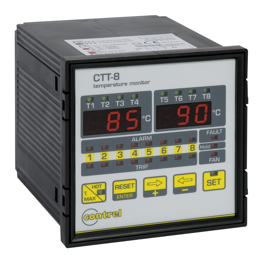
TEMPERATURE MONITOR DEVICE
TEMPERATURE MONITOR DEVICE
TEMPERATURE MONITOR DEVICE
TEMPERATURE MONITOR DEVICE
buttons:
via S. Fereolo, 9
Telefax.
32819
CTT8
CTT8
CTT8
CTT8
1
C.F. E P.I. 08051910159 - C.C.I.A.A. 1199372
E-mail: contrel
USER MANUAL IM 302-U v. 1.2
@contrel.it
Advertisement
Table of Contents

Related Manuals for Contrel CTT8


Summary of Contents for Contrel CTT8
- Page 1 26900 LODI - ITALY - via S. Fereolo, 9 C.F. E P.I. 08051910159 - C.C.I.A.A. 1199372 Tel. ++39(0)371 30207/30761 Telefax. 32819 E-mail: contrel @contrel.it USER MANUAL IM 302-U v. 1.2 TEMPERATURE MONITOR DEVICE TEMPERATURE MONITOR DEVICE TEMPERATURE MONITOR DEVICE TEMPERATURE MONITOR DEVICE...
- Page 2 Alarm and trip set up. The SETUP step concerning alarm threshold starts from the set of channel n.1 and its led placed on measurement display turn on. With the channel 1 led lights, in the same time the turn on ALARM led which it’ s always relative to channel 1 that shows SET step of alarm threshold : Set range from 5°C to trip threshold value - 1 °C.
- Page 3 On display placed on the right one of the frontal panel will be displayed the temperature of measurement warmer channel between CH5 – CH8 inputs. To return on standard measurement display modalities, keep on pushing Hot button for some seconds until the turn-off light indicator. INDICATORS LIGHT TEST Push at the same time buttons ←...
- Page 4 Il costruttore declina ogni responsabilità per eventuali danni a cose o persone derivanti da un uso improprio o non consentito degli strumenti. elettronica srl 26900 LODI - ITALY - Via San Fereolo, 9 tel. ++39 (0)371 30207-30761-35386 fax 32819 E-mail: contrel@contrel.it...
Need help?
Do you have a question about the CTT8 and is the answer not in the manual?
Questions and answers