
Subscribe to Our Youtube Channel
Related Manuals for Contrel EMA-90N


Summary of Contents for Contrel EMA-90N
- Page 1 EMA-90N Electrical Measurement Analyzer User Manual IM128-U v0.74 EMA‐90N User Manual IM128‐U v0.74 Pag. 1 / 32 ...
-
Page 2: Table Of Contents
The information contained herein is the property of Contrel Elettronica Srl, and by law, no part of it may be reproduced, transcribed, stored in any retrieval system, or translated into any language by means (even for internal purposes by the customer) without the express written permission of Contrel Elettronica Srl. -
Page 3: Description
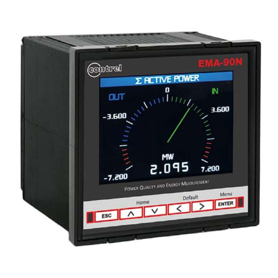
Description The EMA (Electrical Measurement Analyzer) has advanced analysis functions that allow the measurement of the main electrical parameters: voltage, current, frequency, power factor, crest factor, active and reactive power, active and reactive energy. The instrument allows the measurement and analysis in real time of electrical parameters, also verifying the quality of the energy thanks to THD measurement. -
Page 4: Installation
Installation Warning for the user Read carefully the instructions/indications contained in this manual before installing and using the instrument. The instrument described in this manual is intended for use by properly trained staff only. Safety This device has been manufactured and tested in compliance with EN 61010-2 standards. In order to maintain these conditions and to ensure safe operation, it need to comply with the indications and markings contained in the manual. - Page 5 In case of connection in a 3 phase network (without neutral or with neutral not distributed) don’t connect the N terminal. WARNING: If the instrument has the TTA on the current inputs, DON’T connect the S2 terminals to the earth. This connection with only 2 CT (and eventually 2VT) allows to measure accurately the three-phase currents.
- Page 6 In presence of multiple balanced loads in a three-phase network, the instrument calculates the electrical parameters checking a single phase current for each load, allowing to limit the number of CT used. WARNING: If the instrument has the TTA on the current inputs, DON’T connect the S2 terminals to the earth.
- Page 7 EMA‐90N User Manual IM128‐U v0.74 Pag. 7 / 32 ...
-
Page 8: Digital Inputs / Outputs
Digital Inputs / Outputs see the "technical characteristics" section for further information. 4 digital outputs (4DO) 4 digital outputs (4DO) 4 digital outputs (4DO) 6 digital outputs (6DO) 8 digital outputs (8DO) 2 analog outputs (2AO) 4 analog outputs (4AO) 4 digital inputs (4DI) 2 digital inputs (2DI) 4DO+2AO... -
Page 9: Keys Functionality
Keys functionality Directional Keys (Up - Down - Left - Right) The arrow keys are used to change pages in Metering, Energy, Power quality, Graphics, Information and Setup. In the next chapters are shown the maps of how to move between the pages. In the same way the directional keys allow you to move and select the items in the Menu. The Up and Down keys are used to increment and decrement or simply change the value set in the Setup pages. -
Page 10: Menu 1
Menu Metering Instantaneous Instantaneous Voltages Power Min/Max Current Active Average Power factor Reactive Max demand Cos phi Apparent Counters Tan phi Logic expression Power External data Frequency Voltage L-N *: see Instantaneous Voltage L-L **: see Instantaneous (no THD) Current Energy Power quality Graphics... -
Page 11: Visualization And Measures 1
Visualization and measures The analyzer allows to view the measures in different formats: Numerics (measures and energy section) By pressing the up and down keys it is possible to view the instantaneous measures (voltages, currents, powers etc.) while, where they are available, with the right and left keys it is possible to switch to the minimum / maximum relative categories, absolute minimum / maximum, average and maximum demand. -
Page 12: Dimensions 2
Setup General Setup General Password Password Range Default Level 1 [visual] 0 ÷ 999999999 By setting an Level 1 with a value different by zero, it’ll be necessary to input it to change the page showed on display. Level 2 [setup] 0 ÷... - Page 13 Measure Setup Measure Transform ratio Transform ratio Range Default TA ratio – primary / Rogowski - A 1 ÷ 5000 TA ratio – secondary / Rogowski - mV @50Hz 1 ÷ 5000 4° current ratio - primary / Rogowski 4° - A 1 ÷...
- Page 14 Wiring parameters Description Wiring SYSTEM VOLTAGE PHASE VOLTAGE L PHASE VOLTAGE L PHASE VOLTAGE L LINE TO LINE VOLTAGE L LINE TO LINE VOLTAGE L LINE TO LINE VOLTAGE L SYSTEM CURRENT calculated LINE CURRENT L LINE CURRENT L calculated LINE CURRENT L calculated SYSTEM POWER FACTOR...
- Page 15 In the WIRING setup page it’s possible to modify the wiring type and in the DEVICE STATUS page it’s showed the voltage and current wiring state. For the voltage wiring item it is possible to have the following option: ‐ Correct. ‐...
- Page 16 Energies and Counters The analyzer has 16 timebands to differentiate the power consumption. You can schedule the exchange of the timebands using manual (Modbus command), from DI (digital inputs) or Preset (Setup Timeband Mode Preset). With from DI it’s necessary to set the use of digital inputs for this purpose (Setup I/O DI 1, 2, 3, 4 Mode Change TB). With Preset it is necessary to define a Daily plan in which you set the time of transition (maximum 16) from one to the next timeband.
- Page 17 Setup Measure Energies/Counters Holiday Holiday Range Default Month holiday 1 January ÷ December January Day holiday 1 1 ÷ 31 Plan holiday 1 --- ÷ plan 16 Plan used for this holiday. When the plane setting is different from --- the Holiday Plan is enabled. ………………..
- Page 18 User pages The instrument provides the user with six pages configurable. You can choose the type of page (instantaneous values, average values, energies, graphics and setpoint) and its composition (up to 6 measurements for page). If you choose the type setpoint, the text associated to each setpoint can be changed in Setup Setpoint ...
- Page 19 Communication Setup Communication COM 1 & 2 Setting COM 1 & 2 setting Range Default Mode Slave / Master Slave Slaves to read 1 ÷ 20 Number of slave connected in master mode. Master Timeout [ms] 0 ÷ 10000 Time after than it will be set the no slave response flag and increase the NO RESPONSE COUNTER if the answer isn’t received (Master Mode).
- Page 20 Setup Communication M-BUS M-BUS Range Default Node [address MBUS] 1 ÷ 250 Baudrate [kbit/s] 300 / 600 / 1200 / 2400 / 4800 / 9600 / 19200 / 38400 2400 Stop bits 1 / 2 stop bit 1 stop Data format 8-None / 8-Odd / 8-Even 8-Even...
- Page 21 Setup I/O Digital output Digital output X Range Default State 0 / 1 Select 1 for close the DO, 0 to open. Level Active low / Active high Active high Active low: initial state high level. Active high: initial low level status. Mode Status / Pulse / Setpoint Status...
- Page 22 Example: to associate the L1 phase voltage to the analog output it is necessary select instantaneous for the item Measure group and the acronym V1 for the item Measure associated. If the maximum value is set to 300V and 100V to the minimum, with the scale of 0÷20mA, it will have that with 200V as measured voltage, the output will be 10 mA.
- Page 23 Setpoint The instrument provides to the user, functionality that perform multiple actions when a measure exceeds the set limits, in the way to take automatic corrective actions. The setpoint (32 available) are made by 3 main areas: - parameter to be controlled with its limits; - logic to be used;...
- Page 24 Setup Setpoint Setpoint X (da 1 a 32) Range Default Enable Yes / No Enable or disable the setpoint function. Source Internal measures / Measures node X Internal measures Select the instrument from which the measure to analyze it will be read. Group See Acronyms Group table Selection of the group for the actual setpoint if it is set Internal measures as Source.
- Page 25 Example of setting (in the correct order) to set an alarm when the voltage exceed 230V on the phases 1, 2 and 3 (V1 AND V2 AND V3) with saving the event and the switching of a digital output when the alarm is present and when it disappear. SETPOINT 1 (primary) Source: Internal measures Thrend...
- Page 26 The analyzer provides the user with 2 types of logs in each of which you can select up to 14 measures. Only one log can be enabled at the same time, but only after all the settings have been completed (see examples below). Warning: if you erroneously enable a second log while another is already active, you will disable both and delete any saved data.
- Page 27 Smart It is possible to define the measurements of which the average, the min and the max in the set period will be calculated (from 1 min to the end of the year). Setup Log Smart Smart Range Default Enable yes / no...
- Page 28 Acronym tables Acronyms group table Acronym Instantaneous Average Energies Setpoint Acronyms table of Instantaneous group Acronym Description Acronym Description Acronym Description ΣV System Voltage ΣVA System Apparent Power THD A2 THD Current L2 Voltage L1 Apparent Power L1 THD A3 THD Current L3 Voltage L2 Apparent Power L2...
- Page 29 0.5 to 2.5 mm EMA-90N Q E M o w er...
- Page 30 Technical features Auxiliary power supply Voltage range 90÷250 Vac/dc 20÷60 Vac/dc Frequency range 50/60 Hz Protection fuse 5x20 mm - 1A time lag (option 90÷250 Vac/dc) 5x20 mm - 3.15A time lag (option 20÷60 Vac/dc) Power consumption 10VA max – 3VA min (depending on the options and activities) Measures / precision Energy Factory Default: CEI EN 62053-21 compliant –...
- Page 31 Digital input Number of digital inputs 2, 4 Input voltage range Input rated voltage V 24, 48, 115, 230 Vac/dc (only one defined in the order) INPUT Input current Rated input current I : 5mA =all voltages INPUT INPUT INPUT Inputs configuration 2 terminals (A-K) for each input: NPN, PNP Isolation voltage...
- Page 32 EMA‐90N User Manual IM128‐U v0.74 Pag. 32 / 32 ...
Need help?
Do you have a question about the EMA-90N and is the answer not in the manual?
Questions and answers