
Related Manuals for Alpha-InnoTec WZSV 42K3MC


Summary of Contents for Alpha-InnoTec WZSV 42K3MC
- Page 1 Brine/Water Heat Pumps Brine heat station collective Operating Manual WZSV 42K3MC 83072000bUK...
-
Page 2: Table Of Contents
Performance curves .......... 25 Layout ............6 Dimensional drawings ........26 Accessories..........8 Function ............ 8 WZSV 42K3MC ..........26 Control unit ............27 Operation and care ........9 Wall bracket ............27 Energy and environmentally aware Installation plans ..........28 operation ........... -
Page 3: About This Operating Manual
About this operating manual 1.3 Symbols and identification markings This operating manual is part of the unit. Identification of warnings ► Before working on or with the unit read the operating manual carefully and follow it for all Symbol Meaning activities at all times, especially the warnings and Safety-relevant information. -
Page 4: Contact
All procedural instructions in this operating manual is this operating manual can be found on the internet at solely directed at qualified, skilled personnel. any time and is kept up-to-date: Only qualified, skilled personnel is able to carry out ● Germany: www.alpha-innotec.de the work on the unit safety and correctly. Interference by unqualified personnel can cause life-threatening ● www.alpha-innotec.com injuries and damage to property. -
Page 5: Residual Risks
2.4 Residual risks Media harmful to the environment Improper disposal of environmentally harmful media Electric shock (antifreeze, refrigerant) damages the environment: Components in the unit are live with life-threatening ► Collect media safely. voltage. Before working on the unit: ► Dispose of the media in an environmentally com- ► Disconnect unit from power supply. patible way according to the local regulations. -
Page 6: Description
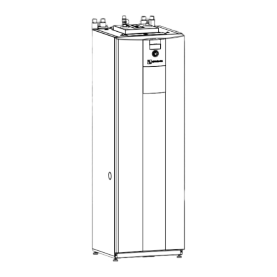
Description ● Negative effect on heat transfer, e.g. formation of coatings, deposits, and associated noises, e.g. boiling noises, flow noises 3.1 Layout ► Note and follow the information in this operating manual for all work on and with the unit. NOTE Unsuitable quality of the fill and make-up This section essentially names water in the heating circuit components relevant for fulfilling the tasks described in this operating manual. The efficiency of the system and the life of the heat generator and the heating components depend Housing with unit components... - Page 7 Module box 5 Valve motor 6 Position of rating plate 7 Overflow valve 8 Venter 9 Electrical switch cabinet 10 Domestic hot water tank sensor 11 Module box 12 Height-adjustable feet (4x) Rating plate Rating plates are attached to the following places on the unit: ● at the top of the heating station ●...
-
Page 8: Accessories
Control unit ● Heating circuit safety package ● Heat source circuit safety package ● Installation package IPSW 1"-28 (Shut-off devices for the heating circuit and for the heat source) ● Air / magnetic sludge separator 3.3 Function Liquid refrigerant is evaporated (evaporator), the energy for this process is environmental heat and comes from the “ground” heat source (collector, borehole heat... -
Page 9: Operation And Care
Delivery, storage, transport Network connection on the control and installation The control can be connected to a computer or network via a network cable. The heating and heat pump controller can then be controlled from the computer or from the network. IMPORTANT Damage to the housing and the unit components due to heavy objects. -
Page 10: Storage
5.2 Storage Unpacking ► Where possible do not unpack the unit until NOTE directly before installation. If the unit is not transported by a pallet truck: ► Store unit protected against: Do not lift off the pallet until after unpacking and dismantling the housing panels. ● Moisture/damp ● Frost Remove plastic films. Ensure that you do not ●... -
Page 11: Installation
5.4 Installation Transport with a handcart Installation room and space requirements NOTE ● If transporting with a handcart the module box must be pushed in. NOTE ● The following figure with the handcart Note and follow the local regulations and shows transporting the unit on its left-hand standards regarding the installation room side;... -
Page 12: Installation And Connection
Installation and connection Disconnect the electrical connections: 4.1. Disconnect 2 white connectors (①) at the bot- tom of the electrical control cabinet. To do this, re- 6.1 Dismantle the module box lease the lugs by pressing on the sides of the con- nectors. - Page 13 Use spanner size SW 37 to unscrew the heating 11. Lift and hold nut (⑨) on the heating flow. flow (⑤). Disconnect the hydraulic connections; to do this, push the pipes (⑥) apart as far as necessary. 12. Slowly and carefully pull out the module box by the carrying lugs (⑩). Ensure that none of the pipes are damaged 13.
-
Page 14: Install The Module Box
6.2 Install the module box IMPORTANT Damage to the copper pipes due to unacceptable Place the module box carefully in the bottom of loading! the heating station and slowly and carefully push ► Secure all connections against twisting. it in. The heat source system has been installed in ... -
Page 15: Connect The Electrical Cables
Connect the unit to the heat source, domestic ● Maximum line length: 30 m. The LIN-bus cable must be a shielded cable of at water pipes and heating circuit least 4 x 0.5 mm² Install shut-off devices at the connections of the heat source and heating circuit. -
Page 16: Installing The Control Panel
6.5 Installing the control panel 3.2. Route cables from underneath through the cable openings in the switch box. 3.3. Connect cables to the respective terminals NOTE ( “Terminal diagram”, page 34). The control can be inserted in a recess in the front panel of the unit or can be installed on Route all cables introduced into the switch box the wall. -
Page 17: Flushing, Filling And Venting
Flushing, filling and venting Push the cable through the opening in the front panel of the unit and from below into the control unit. Remove the front panel of Press the lugs of the control into the openings in the module box the front panel of the unit. Insert cover in the free slot. -
Page 18: Flush And Fill The Heating And Domestic Hot Water Charging Circuit
7.3 Flush and fill the heating and Antifreeze agents from our product range are safe with regard to our units and the accessories domestic hot water charging purchased from us and guarantee compatibility circuit with the listed materials. ► Pressure losses must be observed when selec- Heating water quality ting the antifreeze agent. -
Page 19: Flush, Fill And Vent The Domestic Hot Water Tank
Pull the U-clip (②) off the floor of the valve mo- Position the valve motor (①) on the 3-way switch- tor (①). ing valve (③). Insert the U-clip (②) into the floor of the valve mo- Pull the valve motor carefully upwards and off the 3-way switching valve (③). tor. Ensure that the U-clip has latched into position correctly: Valve motor sits securely on the 3-way. -
Page 20: Insulate Hydraulic Connections
Insulate hydraulic connections Insulate heating circuit, heat source and domestic water pipes according to the local regulations. Open shut-off devices. Perform a pressure test and check for leaks. Insulate the internal piping of the module box with the insulation material from the separate pack included. Insulate external piping on site. Insulate all connections, fittings and pipes. -
Page 21: Commissioning
10 Commissioning 11 Maintenance NOTE NOTE The first filling and initial startup of the We recommend that you sign a maintenance domestic hot water tank must be carried out agreement with accredited heating by qualified personnel. company. Relevant planning & design data of the system is 11.1 Basic principles documented in full. -
Page 22: Faults
12 Faults 12.2 Manually unblock the circulating pumps ► Read out the cause of the fault via the diagnostics Circulating pumps can block due to sediments or lon- program of the heating and heat pump controller. ger standstill periods. This blockage can be removed ► Contact the local partner of the manufacturer or manually. the factory's customer service. Have the fault message and unit number (... -
Page 23: Dismantling And Disposal
13 Dismantling and Disposal 13.1 Dismantling ► Collect all media safely. ► Separate components by their materials. 13.2 Disposal and Recycling ► Dispose of media harmful to the environment according to local regulations, e.g. antifreeze mixture, refrigerant. ► Recycle or ensure proper disposal of unit components and packaging materials according to local regulations. -
Page 24: Technical Data / Scope Of Supply
Technical data / Scope of supply Performance data WZSV 42K3MC Heating capacity | COP for B0/W35 acc. to DIN EN 14511-x kW | COP 2.55 | 4.31 for B0/W45 acc. to DIN EN 14511-x kW | COP 2.42 | 3.34 for B0/W55 acc. -
Page 25: Performance Curves
WZSV 42K3MC Performance curves Qh (kW) Temp„ (°C) Pe (W) 1500 1000 35°C max 55°C max 35°C min 55°C min Temp„ (°C) Temp„ (°C) ∆p„ (bar) ∆p” (bar) 1,000 ̶ ̶ ̶ ̶ ̶ ̶ ̶ ̶ ̶ ̶ ̶ ̶ ̶ ̶ ̶ ̶ ̶ ̶ ̶ ̶ ̶ ̶ ̶ ̶ ̶ ̶ ̶ ̶ ̶ ̶ ̶ ̶ ̶ ̶ ̶ ̶ ̶ ̶ ̶ ̶ ̶ ̶ Δp„... -
Page 26: Dimensional Drawings
WZSV 42K3MC Dimensional drawings ↓ ↑ ↑↓ > 250 > 250 Pos. Pos. Name Name Dim. Dim. Heating water outlet (flow) Heating water outlet (flow) Ø 28 *) Ø 28 *) Pos. Bezeichnung Dim. Heat source inlet (in heat pump) Heat source inlet (in heat pump) Ø... -
Page 27: Control Unit
Schutzvermerk ISO 16016 beachten Dimensional drawings Control unit Schutzvermerk ISO 16016 beachten All dimensions in mm.. All dimensions in mm.. Bohrschablone Wall bracket Blattformat: A4 hoch Allgemein- Maßstab Det. Maßstab Oberflächen toleranz Werkstoff Gewicht Datum Name Benennung Maßbild WZS Erstellt 18.11.14 Brueckner Gepr. -
Page 28: Installation Plan 1
WZSV 42K3MC Installation plan 1 1000 > 1 Legende: DE819537 Alle Maße in mm Version 1 Freiraum für Servicezwecke Freiraum für funktionsnotwendiges Zubehör Keys: UK819537 Oberkante Fertigfussboden Rh min. Raumhöhe Minimum All dimensions in mm. Version 1 Free space for service purposes Zust. -
Page 29: Installation Plans
WZSV 42K3MC Installation plan 2 1000 > 1 Legende: DE819537 Alle Maße in mm Version 2 Freiraum für Servicezwecke Freiraum für funktionsnotwendiges Zubehör Keys: UK819537 Oberkante Fertigfussboden Rh min. Raumhöhe Minimum All dimensions in mm. Version 2 Free space for service purposes Zust. -
Page 30: Installation Plan 3
WZSV 42K3MC Installation plan 3 > 600 > 1 > 1 Legende: DE819537 Alle Maße in mm Keys: UK819537 Version 3 Freiraum für Servicezwecke 1000 All dimensions in mm. Oberkante Fertigfussboden Rh min. Raumhöhe Minimum Version 3 Free space for service purposes Finished floor level Zust. - Page 31 Subject to technical amendments without prior notice | 83072000bUK | ait-deutschland GmbH...
-
Page 32: Hydraulic Integration
WZSV 42K3MC Hydraulic integration Subject to technical amendments without prior notice | 83072000bUK | ait-deutschland GmbH... -
Page 33: Keys Hydraulic Integration
Subject to technical amendments without prior notice | 83072000bUK | ait-deutschland GmbH... -
Page 34: Terminal Diagram
WZSV 42K3MC Terminal diagram 1~N/PE/230V/50Hz 1~N/PE/230V/50Hz 3~N/PE/400V/50Hz OUT 4 OUT 5 OUT 6 OUT 7 OUT 8 OUT 9 OUT 10 OUT 11 OUT 12 OUT 13 OUT 14 OUT 15 OUT 16 OUT 17 NTC 6 NTC 7 NTC 8 TRL ext. - Page 35 Circuit diagram 1/4 WZSV 42K3MC Subject to technical amendments without prior notice | 83072000bUK | ait-deutschland GmbH...
- Page 36 WZSV 42K3MC Circuit diagram 2/4 OUT 5 OUT 14 OUT 13 OUT 17 OUT6 PWM2 Refer to protection notice ISO 16016. Subject to technical amendments without prior notice | 83072000bUK | ait-deutschland GmbH...
-
Page 37: Circuit Diagrams
Circuit diagram 3/4 WZSV 42K3MC braun / blau weiß grün gelb rosa blau violett grau / rosa rot / blau weiß / grün weiß / blau grau / braun rosa / braun NTC12 NTC13 NTC14 NTC15 Refer to protection notice ISO 16016. - Page 38 WZSV 42K3MC Circuit diagram 4/4 NTC11 Refer to protection notice ISO 16016. Subject to technical amendments without prior notice | 83072000bUK | ait-deutschland GmbH...
- Page 39 Subject to technical amendments without prior notice | 83072000bUK | ait-deutschland GmbH...
- Page 40 GmbH Industriestraße 3 D-95359 Kasendorf E info@alpha-innotec.de W www.alpha-innotec.de alpha innotec – an ait-deutschland GmbH brand...
Need help?
Do you have a question about the WZSV 42K3MC and is the answer not in the manual?
Questions and answers