
Related Manuals for Nordson ARAG orion2 VISUAL FLOW


Summary of Contents for Nordson ARAG orion2 VISUAL FLOW
- Page 1 ELECTROMAGNETIC FLOWMETER 462X2AXXXXX Software rel. 2.x.x INSTALLATION, USE AND MAINTENANCE...
-
Page 2: Table Of Contents
LEGEND OF SYMBOLS = Generic danger = Warning CONTENTS MANUAL USE MODES ....................................3 RESPONSIBILITY ......................................3 INTENDED USE ......................................3 Product description ..................................3 USE LIMITS ........................................3 RISKS AND PROTECTIONS ..................................3 PRECAUTIONS ......................................3 1 Package content ....................................... 4 2 INSTALLATION ...................................... -
Page 3: Manual Use Modes
INTRODUCTION • MANUAL USE MODES THE INSTALLATION MUST BE CARRIED OUT BY AUTHORIZED AND SKILLED PERSONNEL ONLY. ARAG IS NOT RESPONSIBLE FOR ANY INSTALLATION CARRIED OUT BY UNAUTHORIZED OR UNSKILLED PERSONNEL. • RESPONSIBILITY It is the responsibility of the installer to perform the installation "in a workmanlike manner" in order to ensure proper operation of the system. ARAG recommends using its components to install control systems. -
Page 4: Package Content
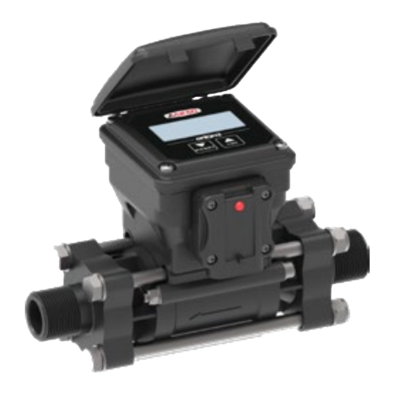
INSTALLATION PACKAGE CONTENT The package includes: Electromagnetic flowmeter orion2 VISUAL FLOW (the flange shown is indicative) TO BE ORDERED SEPARATELY (Ref. ARAG general catalog): Power cable Fig. 1 INSTALLATION Dimensions Threaded coupling Flange material Nylon® G 3/4" M 185 (7 .3") Brass G 3/4"... -
Page 5: Assembly
INSTALLATION Assembly 2.2.1 General precautions Install the flowmeter at least 20 cm from the elements that could cause turbulence inside the pipe (valves, bends, bottlenecks, etc.). The flowmeter can be installed either horizontally or vertically. WARNING: For proper sealing of the flowmeter, use ONLY the appropriate ARAG assembly kit (Ref. ARAG General Catalog - Accessories for modular valves). -
Page 6: Hydraulic Connections
INSTALLATION 2.2.3 Hydraulic connections For the connection to the system, use suitable fittings (Ref. ARAG General catalog). Avoid bottlenecks or twists before the fittings and on pipes. For the connections, use pipes and fittings duly dimensioned for the system operating pressure. Hose tails must be tightened with special metal clips ensuring a perfect sealing even at high pressure values. -
Page 7: Programming
SETTING PROGRAMMING Tests and checks before setting Before setup, check: • that all components are correctly installed; • the correct connection to the power source; • the component connection. Failure to correctly connect system components or to use specified components might damage the device or its components. Using the keys RESET RESET... -
Page 8: Function Mode
SETTING Function ModE 3.2.1.1 It is possible to set 3 different operating modes: MODE 0 = Tank filling count with pump control command (0 ÷ 9999 EU: I [default setting] - US: Gal) MODE 1 = Flowrate display MODE 2 = Tank filling count with pump control command (0 ÷ 999.9 EU: I - US: Gal). 1) Press a few times to display the active operating mode;... -
Page 9: Ual " Valve Actuation Time
SETTING 3.2.1.5 “ ” valve actuation time This parameter allows setting the time that the valve installed on the system takes to complete the closing operation; by setting this data, the flowmeter will be able to anticipate the exact moment at which to start the closing operation, preventing more product from entering when the set value is reached. = 0 ÷... -
Page 10: Flowmeter Constant Setting
SETTING 3.3.1 Flowmeter constant setting 1) After performing the start-up procedure indicated in paragraph 3.1, the device switches to the display of the currently set flowmeter constant CoSt value alternating with the “ ” indication. 2) To change the figure, hold down the keys simultaneously until the screen “ ”... -
Page 11: Use
While the system is in use, the flowmeter sends pulses to the computer, which, based on the previously set constant value, will indicate the instant flowrate. An LED on the connector housing indicates the status of the device: LED off: The device is not powered. -
Page 12: Operation Of Mode 0 - Mode 2
4.1.3 Operation of Mode 0 - Mode 2 1) After start-up the amount of fluid to be poured into the tank is displayed. Strt 2) To start the filling procedure, keep key pressed until the message “ ” appears; the value corresponding to the total amount of fluid poured into the tank is displayed in real time. -
Page 13: Resetting The Counter Of The Liquid Filled In The Tank
4.2.2 Resetting the counter of the liquid filled in the tank 1) Access the display of the total liquid filled in the tank ( 4.1.2 key until the message “ ” is displayed. 2) To reset the total amount of liquid filled in the tank to zero, press and hold the RESET 3) At this point, the display will show the message “... -
Page 14: Maintenance / Diagnostics / Repairs
MAINTENANCE / DIAGNOSTICS / REPAIRS MAINTENANCE / DIAGNOSTICS / REPAIRS Precautions for maintenance operations and for cleaning the external parts • DISCONNECT THE POWER CABLES. • WEAR SUITABLE PERSONAL PROTECTION EQUIPMENT, OVERALLS, GLOVES AND FACE MASK. • DO NOT CARRY OUT ANY OPERATION ON THE SYSTEM IF INDOORS OR IN POORLY VENTILATED AREAS. •... -
Page 15: Technical Data
TECHNICAL DATA TECHNICAL DATA ELECTRICAL FEATURES • Power supply voltage 10 ÷ 16 Vdc • Consumption 300 mA • Liquid minimum conductivity 50 μS/cm ENVIRONMENTAL FEATURES • Operating temperature 0 °C ÷ 60 °C / +32 °F ÷ +140 °F •... -
Page 16: Guarantee Terms
TECHNICAL DATA GUARANTEE TERMS ARAG s.r.l. guarantees this apparatus for a period of 360 days (1 year) from the date of sale to the client user (date of the goods delivery note). The components of the apparatus, that in the unappealable opinion of ARAG are faulty due to an original defect in the material or production pro- cess, will be repaired or replaced free of charge at the nearest Assistance Center operating at the moment the request for intervention is made. - Page 17 Only use genuine ARAG accessories or spare parts to make sure manufacturer guaranteed safety conditions are maintained in time. Always refer to the Internet address www.aragnet.com Via Palladio, 5/A 42048 RUBIERA (Reggio Emilia) - ITALY Tel. +39 0522 622011 Fax +39 0522 628944 www.aragnet.com info@aragnet.com...
Need help?
Do you have a question about the ARAG orion2 VISUAL FLOW and is the answer not in the manual?
Questions and answers