Table of Contents
Advertisement
Quick Links
www.ti.com
User's Guide
DLP5532PROJHBQ1EVM Evaluation Module
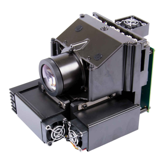
The DLP5532PROJHBQ1EVM Evaluation Module (EVM) is an automotive projector designed to support high
brightness transparent window display applications such as advertisement and vehicle-to-vehicle and vehicle-
to-pedestrian communication. The DLP5532PROJQ1EVM supports proof of concept demos and speeds up
the development cycle by providing a high performance projector solution complete with optics, LED light
sources, and adjustable throw distance. This EVM includes a complete electronic subsystem designed to control
the DLP5532-Q1 chipset. The DLP5532-Q1 chipset consists of the DLP5532-Q1, the DLPC230-Q1, and the
TPS99000-Q1. This projector enables high brightness displays with a luminous flux output of 600 lumens and
contrast of 600:1 in a compact package. With additional development of the LED driver board - including higher
LED current support per channel and a robust thermal design - this projection engine can provide upwards of
1,000 lumens. The projection lens is designed for a throw ratio of 1.8, 100% offset, and an adjustable focus
distance from 450 mm to 1000 mm.
The DLP5532PROJHBQ1EVM is not a production design. It is intended for evaluation only.
DLPU107 – MAY 2022
Submit Document Feedback
ABSTRACT
Figure 1-1. The DLP5532PROJHBQ1EVM
Copyright © 2022 Texas Instruments Incorporated
DLP5532PROJHBQ1EVM Evaluation Module
1
Advertisement
Table of Contents

Related Manuals for Texas Instruments DLP5532PROJHBQ1EVM


Summary of Contents for Texas Instruments DLP5532PROJHBQ1EVM
-
Page 1: Figure 1-1. The Dlp5532Projhbq1Evm
DLP5532PROJHBQ1EVM Evaluation Module ABSTRACT The DLP5532PROJHBQ1EVM Evaluation Module (EVM) is an automotive projector designed to support high brightness transparent window display applications such as advertisement and vehicle-to-vehicle and vehicle- to-pedestrian communication. The DLP5532PROJQ1EVM supports proof of concept demos and speeds up the development cycle by providing a high performance projector solution complete with optics, LED light sources, and adjustable throw distance. -
Page 2: Table Of Contents
Table of Contents www.ti.com Table of Contents 1 User Guide Overview................................3 1.1 What is in the DLP5532PROJHBQ1EVM ......................... 1.2 Specifications..................................2 Quick Start.....................................10 2.1 Kit Assembly Instructions..............................2.2 Software Installation.................................13 2.3 Powering-Up EVM................................13 2.4 Connecting EVM to the DLPC230-Q1 Control Program.................... -
Page 3: User Guide Overview
EVM. 1.1 What is in the DLP5532PROJHBQ1EVM The DLP5532PROJHBQ1EVM consists of a controller PCB, an illumination driver PCB, cables, and a USB to SPI adapter. The DLP5532PROJHBQ1EVM also includes an optical module designed to combine with the electronic subsystem for evaluation of a fully functioning projector in an automotive setting. -
Page 4: Table 1-1. Controller Pcb Ports
On: Hold in boot PROJ_ON Off: Turn off system On: Turn on system On state is toward the outer edge of the board (Figure 1-1) DLP5532PROJHBQ1EVM Evaluation Module DLPU107 – MAY 2022 Submit Document Feedback Copyright © 2022 Texas Instruments Incorporated... -
Page 5: Figure 1-2. Dlp5532Projhbq1Evm Illumination Driver Pcb
Depending on operating conditions, some parts and surfaces of the PCB can be hot. CAUTION Hot surface. Contact might cause burns. Do not touch! Figure 1-2. DLP5532PROJHBQ1EVM Illumination Driver PCB (Top) DLPU107 – MAY 2022 DLP5532PROJHBQ1EVM Evaluation Module Submit Document Feedback... -
Page 6: Figure 1-3. Dlp5532Projhbq1Evm Illumination Driver Pcb (Bottom)
User Guide Overview www.ti.com Figure 1-3. DLP5532PROJHBQ1EVM Illumination Driver PCB (Bottom) The illumination driver PCB contains the ports listed in Table 1-4. Note that all ports with the schematic reference J20# are located on the bottom of the illumination driver PCB board. -
Page 7: Figure 1-4. Evm Cables
User Guide Overview 1.1.3 EVM Cables The DLP5532PROJHBQ1EVM kit contains the cables and FTDI USB to SPI/I2C adapter listed in Table 1-6. Table 1-6. EVM Cables Name Reference Quantity Micro HDMI Cable Input Power Cable Host SPI Cable FTDI SPI Host Adapter... -
Page 8: Specifications
The controller and illumination driver PCBs have a UL flame rating of 130°C maximum. This is not a production design. It is intended for evaluation only. DLP5532PROJHBQ1EVM Evaluation Module DLPU107 – MAY 2022 Submit Document Feedback Copyright © 2022 Texas Instruments Incorporated... -
Page 9: Table 1-9. Typical Timing For Supported Source Resolutions
1.2.4 SPI and I C Timing For more information on SPI and I C specifications, see the DLPC230-Q1 Automotive DMD Controller for the DLP553x-Q1 Chipset data sheet. DLPU107 – MAY 2022 DLP5532PROJHBQ1EVM Evaluation Module Submit Document Feedback Copyright © 2022 Texas Instruments Incorporated... -
Page 10: Quick Start
Quick Start www.ti.com 2 Quick Start Use the following instructions to setup the DLP5532PROJHBQ1EVM and PC for video input and control communication. 2.1 Kit Assembly Instructions A diagram of all connections is shown in Figure 2-1. 1. Connect the host SPI/I2C cable to the controller PCB (J2/J1) and the FTDI adapter. Connect the FTDI adapter’s USB cable to PC. -
Page 11: Figure 2-2. Ftdi To Spi Cable Connection
3. Connect black wire of FTDI cable (Ground) to black wire of I2C cable. 4. Connect green wire of FTDI cable (Serial In) to green wire of I2C cable. The following provide visual references for the fan cable connections involving the DLP5532PROJHBQ1EVM projector itself. -
Page 12: Figure 2-4. Fan Connection Cables
Quick Start www.ti.com Figure 2-4. Fan Connection Cables The following provide visual references for the LED cable connections involving the DLP5532PROJHBQ1EVM projector itself. Note The cables are already connected and assembled by the manufacturer. Please only disassemble if required. There is a back plate held together by four screws. The LED cables have no locking tabs and can be pulled out with force. -
Page 13: Software Installation
2-6). Note, the Cheetah must be connected to a computer with USB cable for it to show up in the drop-down menu. Figure 2-6. Connecting to the DLPC230-Q1 Using the DLPC230-Q1 Automotive Control Program DLPU107 – MAY 2022 DLP5532PROJHBQ1EVM Evaluation Module Submit Document Feedback Copyright © 2022 Texas Instruments Incorporated... -
Page 14: Steps To Reprogram The Onboard Flash Memory
Cheetah Adapter. 2.5 Steps to Reprogram the Onboard Flash Memory The DLP5532PROJHBQ1EVM comes with onboard serial Flash that is pre-programmed with software and basic configuration. The software and configuration can be updated by reprogramming the serial Flash with the DLPC230-Q1 Automotive Control Program. -
Page 15: Optical Engine Requirements And Specifications
Optical Engine Requirements and Specifications 3 Optical Engine Requirements and Specifications The DLP5532PROJHBQ1EVM includes an optical projection system that can be used for transparent window display applications. The optical specifications are listed in Table 3-1. Table 3-1. Optical Module Specifications... - Page 16 STANDARD TERMS FOR EVALUATION MODULES Delivery: TI delivers TI evaluation boards, kits, or modules, including any accompanying demonstration software, components, and/or documentation which may be provided together or separately (collectively, an “EVM” or “EVMs”) to the User (“User”) in accordance with the terms set forth herein.
- Page 17 www.ti.com Regulatory Notices: 3.1 United States 3.1.1 Notice applicable to EVMs not FCC-Approved: FCC NOTICE: This kit is designed to allow product developers to evaluate electronic components, circuitry, or software associated with the kit to determine whether to incorporate such items in a finished product and software developers to write software applications for use with the end product.
- Page 18 www.ti.com Concernant les EVMs avec antennes détachables Conformément à la réglementation d'Industrie Canada, le présent émetteur radio peut fonctionner avec une antenne d'un type et d'un gain maximal (ou inférieur) approuvé pour l'émetteur par Industrie Canada. Dans le but de réduire les risques de brouillage radioélectrique à...
- Page 19 www.ti.com EVM Use Restrictions and Warnings: 4.1 EVMS ARE NOT FOR USE IN FUNCTIONAL SAFETY AND/OR SAFETY CRITICAL EVALUATIONS, INCLUDING BUT NOT LIMITED TO EVALUATIONS OF LIFE SUPPORT APPLICATIONS. 4.2 User must read and apply the user guide and other available documentation provided by TI regarding the EVM prior to handling or using the EVM, including without limitation any warning or restriction notices.
- Page 20 Notwithstanding the foregoing, any judgment may be enforced in any United States or foreign court, and TI may seek injunctive relief in any United States or foreign court. Mailing Address: Texas Instruments, Post Office Box 655303, Dallas, Texas 75265 Copyright © 2019, Texas Instruments Incorporated...
- Page 21 TI products. TI’s provision of these resources does not expand or otherwise alter TI’s applicable warranties or warranty disclaimers for TI products. TI objects to and rejects any additional or different terms you may have proposed. IMPORTANT NOTICE Mailing Address: Texas Instruments, Post Office Box 655303, Dallas, Texas 75265 Copyright © 2022, Texas Instruments Incorporated...
Need help?
Do you have a question about the DLP5532PROJHBQ1EVM and is the answer not in the manual?
Questions and answers