Table of Contents
Advertisement
Quick Links
Service Manual
Aspect
Register your machine:
www.lincolnelectric.com/registration
Authorized Service and Distributor Locator:
www.lincolnelectric.com/locator
Save for future reference
Date Purchased
Code: (ex: 10859)
Serial: (ex: U1060512345)
SVM10420
| Issue D ate Apr-22
© Lincoln Global, Inc. All Rights Reserved.
230 AC/DC
®
For use with machines having Code Numbers:
12732
Advertisement
Chapters
Table of Contents

Related Manuals for Lincoln Electric Aspect 230 AC/DC


Summary of Contents for Lincoln Electric Aspect 230 AC/DC
- Page 1 Service Manual Aspect 230 AC/DC ® For use with machines having Code Numbers: 12732 Register your machine: www.lincolnelectric.com/registration Authorized Service and Distributor Locator: www.lincolnelectric.com/locator Save for future reference Date Purchased Code: (ex: 10859) Serial: (ex: U1060512345) SVM10420 | Issue D ate Apr-22 ©...
- Page 2 THANK YOU FOR SELECTING A QUALITY PRODUCT BY KEEP YOUR HEAD OUT OF THE FUMES. DON’T get too close to the arc. LINCOLN ELEC TRIC. Use corrective lenses if necessary to stay a reasonable distance away from the arc. READ and obey the Safety Data PLEASE EXAMINE CARTON AND EQUIPMENT FOR Sheet (SDS) and the warning label DAMAGE IMMEDIATELY...
- Page 3 P.O. Box 351040, Miami, Florida 33135 or CSA Standard W117.2. A Free copy of “Arc Welding Safety” booklet E205 2.a. Electric current ˜owing through any conductor is available from the Lincoln Electric Company, 22801 causes localized Electric and Magnetic Fields (EMF). St. Clair Avenue, Cleveland, Ohio 44117-1199.
- Page 4 SAFETY ELECTRIC SHOCK ARC RAYS CAN BURN. CAN KILL. 3.a. The electrode and work (or ground) circuits are 4.a. Use a shield with the proper filter and cover plates to protect your electrically “hot” when the welder is on. Do eyes from sparks and the rays of the arc when welding or not touch these “hot”...
- Page 5 SAFETY WELDING AND CUTTING CYLINDER MAY EXPLODE IF SPARKS CAN CAUSE DAMAGED. FIRE OR EXPLOSION. 7.a. Use only compressed gas cylinders containing the correct shielding gas for the process used 6.a. Remove fire hazards from the welding area. If and properly operating regulators designed for this is not possible, cover them to prevent the welding sparks the gas and pressure used.
- Page 6 TABLE OF CONTENTS CONTENT/DETAILS MAY BE CHANGED OR UPDATED WITHOUT NOTICE. FOR MOST CURRENT INSTRUCTION MANUALS, GO TO PARTS.LINCOLNELECTRIC.COM.
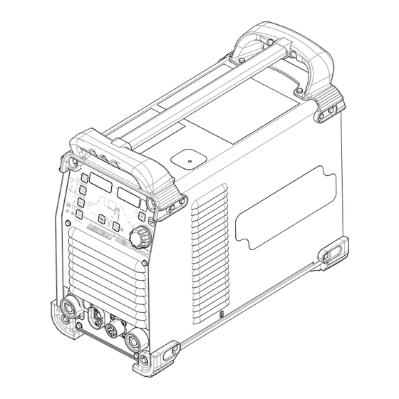
- Page 7 ASPECT ® 230 AC/DC INSTALLATION The Aspect ® 230 AC/DC is an inverter based arc welding power source optimized for AC/DC TIG (GTAW) and AC/DC Stick (SMAW) welding. The Aspect ® 230 AC/DC includes TIG features such as Intellistart™, AC Auto Balance ®...
- Page 8 INSTALLATION ASPECT ® 230 AC/DC TECHNICAL SPECIFICATIONS ASPECT 230 AC/DC ® RECOMMENDED FUSE SIZES 1 (K4340-1) INPUT MAXIMUM TIME DELAY FUSE POWER SOURCE INPUT VOLTAGE VOLTAGE / INPUT AMPERE AND CURRENT PHASE / RATING BREAKER 3-Phase NA/19/17/10/9 Max Input Amperes FREQUENCY AMPERAGE 120V/208V/230V/400V/460V...
- Page 9 ASPECT ® 230 AC/DC INSTALLATION INSTALLATION MACHINE GROUNDING AND HIGH FREQUENCy SAFETy PRECAUTIONS INTERFERENCE PROTECTION Read entire installation section ® Locate the Aspect 230 AC/DC away from radio controlled machinery. before starting installation. The normal operation of the Aspect ® 230 AC/DC may adversely affect the operation of RF controlled equipment, which may result in bodily WARNING...
- Page 10 ASPECT ® 230 AC/DC INSTALLATION 8. When the welder is enclosed in a metal building, several good earth driven electrical grounds (as in 5 above) around the INPUT VOLTAGE SELECTION periphery of the building are recommended. The Aspect ® 230 AC/DC automatically adjusts to work with the input Failure to observe these recommended installation procedures can voltages listed on the rating plate.
- Page 11 ASPECT ® 230 AC/DC INSTALLATION OUTPUT CONNECTIONS FIGURE A.2 6-PIN REMOTE CONTROL CONNECTOR Function Wiring REMOTE POTENTIOMETER, 10K 6-PIN REMOTE REMOTE POTENTIOMETER, WIPER CONTROL REMOTE POTENTIOMETER, COMMON CONNECTOR FOR REMOTE TRIGGER, COMMON HAND/FOOT TRIGGER, INPUT AMPTROL. GROUND 1. Twist-Mate Electrode / Gas Output Connector 2.
- Page 12 ASPECT ® 230 AC/DC INSTALLATION AIR COOLED TIG TORCH WITH WIRED FOOT PEDAL CONNECTION DIAGRAM Refer to the following connection diagrams for specific information on connecting water cooled and air cooled torches. REGULATOR FLOWMETER GAS HOSE TO WORK STUD K2394-1 Ground Clamp Set (Includes electrode holder and cable) WORK CLAMP WORK PIECE...
- Page 13 ASPECT ® 230 AC/DC OPERATION OPERATION CASE FRONT CONTROLS CASE BACK CONTROLS (See figure B.1) (See figure B.2) FIGURE B.1 FIGURE B.2 1. User Interface – For selecting process & parameters 7. Input Power Cord 2. Control Knob – Used to control machine output setting and to 8.
- Page 14 ASPECT ® 230 AC/DC OPERATION GRAPHIC SYMBOLS THAT APPEAR ON THIS MACHINE OR IN THIS MANUAL CIRCUIT BREAKER SAVE SMAW 3 PHASE INVERTER THREE PHASE HIGH TEMPERATURE INPUT POWER DIRECT CURRENT AC AUTO ALTERNATING OPEN CIRCUIT RECALL BALANCE ® CONNECTION CURRENT VOLTAGE MENUS...
- Page 15 ASPECT ® 230 AC/DC OPERATION Polarity USER INTERFACE CONTROLS This switch allows the user to set the polarity of the process in use. For DC GTAW welding the output is DCEN and for DC SMAW welding the output is DCEP. (See Figure B.4) FIGURE B.3 FIGURE B.4 (Changing Polarity to DCEN for SMAW welding is done in the...
- Page 16 ASPECT ® 230 AC/DC OPERATION 4-Step Functionality 1. 2-Step (See Figure B.7 and B.8) – With 2-step trigger and a TIG welding mode selected, the following weld sequence will occur. (See Figure B.10) If a standard foot amptrol is connected, it will take control of FIGURE B.10 most sequencer functions, but pre-flow, starting current, finishing current, and post-flow can be defined.
- Page 17 ASPECT ® 230 AC/DC OPERATION AC WAVESHAPE 3. AC Balance: AC balance controls the amount of time, as a percentage, that the polarity is electrode negative. (See Figure This switch allows the operator to customize the arc performance for B.14) (35-99%) TIG welding in AC polarity only.
- Page 18 ASPECT ® 230 AC/DC OPERATION SEQUENCER FUNCTIONS PULSE SEQUENCER FUNCTIONS The sequencer allows for customization of the TIG welding operation To access the pulse menu, select the Pulse Sequencer button once both in AC & DC- polarities. Pressing the “SEL” button will cycle and then cycle through the Sequencer with the SEL button.
- Page 19 ASPECT ® 230 AC/DC OPERATION MEMORy SELECTION: Saving Memory Settings The memory function allows the operator to save up to 9 specific In order to save process settings into a memory location it is first welding procedures. This memory switch has two functions: necessary to press the memory button so that the “memory save”...
- Page 20 ASPECT ® 230 AC/DC OPERATION Memory Recall Settings Status Lights: (See Figure B.24) (See Figure B.22) There are 4 status lights located between the voltage and amperage In order to recall process settings it is first necessary to press the displays.
- Page 21 ASPECT ® 230 AC/DC OPERATION Hold Select button for 5 seconds to enter Menu “GTAW.” 5 Seconds Setup Menu "GTAW" TIG Settings TIG Settings Press SEL to cycle through & rotate knob to change then SEL to save ‘A” to exit Display Item Choices...
- Page 22 ASPECT ® 230 AC/DC OPERATION Hold Pulse button for 5 seconds to enter Menu “SMAW.” 5 Seconds Setup Menu "SMAW" Stick Settings Display Item Choices Description 0-75 for soft stick FRCE Arc Force Specify your Arc Force setting 75-200 for crisp stick 0-75 for soft stick Specify your Hot Start setting HSTR...
- Page 23 ASPECT ® 230 AC/DC OPERATION Hold both Select and Pulse buttons for 5 seconds to enter Menu “SYS.” 5 Seconds Then press ‘SEL’ to cycle through. To change, rotate knob then press ‘SEL’ to save “A’ to exit Setup Menu “SYS” System Settings Display Item...
- Page 24 ASPECT ® 230 AC/DC OPERATION Appendix A.1 Volt and Amp meter display while welding and idle. While welding, the machine will show actual voltage and amperage on the meters. When the welding arc is extinguished, the meters will display (and flash) the final voltage and amperage of that weld for 5 seconds. Figure B.25 ---- A.2 Green Mode...
- Page 25 ASPECT ® 230 AC/DC OPERATION A.4 4-Step Trigger with Restart Sequence 4-Step trigger with restart can be enabled in setup menu “GTAW” by switching 4RST to ON. If 4RST is ON, a TIG mode is selected, and 4-step is selected on the output section of the machine, the following sequence will occur. (3A) This sequence is the same as 4-step, except when the switch is released during the finishing current, welding current will ramp up again to the operating amperage.
- Page 26 ASPECT ® 230 AC/DC ACCESSORIES GENERAL OPTIONS / K2266-1 – TIG-Mate ™ 17 Air Cooled TIG Torch Starter Pack. One complete easy-to-order kit packaged in its own portable car- rying case. Includes: PTA-17 torch, parts kit, Harris ACCESSORIES flowmeter/regulator, 10 ft. gas hose, Twist-Mate™ adapter, work clamp and cable.
- Page 27 ASPECT ® 230 AC/DC MAINTENANCE MAINTENANCE OVERLOAD PROTECTION Safety Precautions FAN-AS-NEEDED (F.A.N.) The Aspect ® 230 AC/DC has the F.A.N. circuit feature, which means WARNING the cooling fan will operate only as needed to assure proper machine cooling. This helps reduce the amount of dust and dirt drawn into the ELECTRIC SHOCK can kill.
-
Page 28: Table Of Contents
OUTPUT POWER BOARD, OUTPUT CONTROL BOARD..................E5 HIGH FREQUENCY BOARD, HIGH FREQUENCY TRANSFORMER, CURRENT TRANSDUCER (LEM)......E6 MACHINE PROTECTION..........................E7 LED'S AND FAN CONDITIONS UPON INITIAL POWER-UP OF THE ASPECT 230 AC/DC MACHINE......E8 PULSE WIDTH MODULATION ........................... E10 INSULATED GATED BI-POLAR TRANSISTOR OPERATION .................. E11... -
Page 29: Functional Description
Control Board User Input Power Board Interface Set Point Signals Board Rectiÿed Input Super +15VDC +5 VDC Position Circuit Output Trigger (+/- 15 VDC) Output Set Points Fans Remote Solenoid To Cooler Control Receptacle Receptacle ASPECT 230 AC/DC Figure E.1... -
Page 30: Input Section
THEORY OF OPERATION ASPECT ® 230 AC/DC INPUT SECTION INPUT LINE SWITCH, RECTIFIER, INPUT POWER BOARD, BUCK/BOOST INVERTER BOARD The single or three phase voltage is applied to the machine via an input line switch. This AC input voltage is then applied to a rectifier. The resultant DC voltage is applied to both the Input Power Board and the Buck/ Boost Inverter Board. -
Page 31: Input Power Board, User Interface Board
THEORY OF OPERATION ASPECT ® 230 AC/DC INPUT POWER BOARD, USER INTERFACE BOARD The Input Power Board regulates the DC Bus voltage ((390VDC) by controlling the firing signals of the Buck/ Boost IGBTs that are located on the Buck/Boost Inverter Board. It develops these Pulse Wave Modulation (PWM) firing signals from the “Set-Point”... -
Page 32: Buck/Boost Inverter Board, Main Transformer
The amount of “ON TIME” for the IGBTs determines the board is to produce a constant 390 VDC regardless of output power produced by the Aspect 230 AC/DC. See input voltage. The buck boost circuit consists of a buck IGBT Operation and Pulse Width (PWM) Operation in converter followed by a boost converter. -
Page 33: Output Power Board, Output Control Board
THEORY OF OPERATION ASPECT ® 230 AC/DC OUTPUT POWER BOARD, OUTPUT CONTROL BOARD The Output Power Board rectifies the AC voltage from the secondary windings in the Main Transformer and passes it to the AC switches, which are controlled by the Output Control Board. -
Page 34: High Frequency Board, High Frequency Transformer, Current Transducer (Lem)
THEORY OF OPERATION ASPECT ® 230 AC/DC HIGH FREQUENCY BOARD, HIGH FREQUENCY TRANSFORMER, CURRENT TRANSDUCER (LEM) When the Input Power Board receives a trigger signal the High Frequency Board Receives 24VDC power and also command signals from the Input Power Board. The high frequencies created on the High Frequency Board are sent to the primary winding of the High Frequency Transformer for three seconds or until the... -
Page 35: Machine Protection
THEORY OF OPERATION ASPECT ® 230 AC/DC MACHINE PROTECTION THERMOSTATIC PROTECTION This welder has thermostatic protection from excessive duty cycles, overloads, loss of cooling, and excessive ambient temperatures. When the welder is subjected to an overload, or inadequate cooling, the primary coil thermostat and/or secondary coil thermostat will open. - Page 36 ® 230 AC/DC LED'S AND FAN CONDITIONS UPON INITIAL POWER-UP OF THE ASPECT 230 AC/DC The fans will run at high speed for about 5 seconds and then go to low speed until machine output is enabled. PC BOARD LED'S...
- Page 37 THEORY OF OPERATION ASPECT ® 230 AC/DC BUCK - BOOST BOARD LED LEGEND FUNCTION COLOR INDICATION Buck Supply LED 1 Green Normal Status ON Created On only when input LED 2 Boost Driver Active Green voltage is below 380VAC Buck Driver is LED 3 Green Normal Status ON...
-
Page 38: Pulse Width Modulation
THEORY OF OPERATION ASPECT ® 230 AC/DC TYPICAL IGBT OUTPUTS MINIMUM OUTPUT (Dwell or Off Time) MAXIMUM OUTPUT (Dwell or Off Time) PULSE WIDTH MODULATION The term PULSE WIDTH MODULATION is used to The positive portion of the signal represents one describe how much time is devoted to conduction IGBT group conducting for 2 microsecond. -
Page 39: Insulated Gated Bi-Polar Transistor Operation
THEORY OF OPERATION ASPECT ® 230 AC/DC IGBT OPERATION POSITIVE VOLTAGE APPLIED GATE GATE SOURCE SOURCE BODY REGION BODY REGION DRAIN DRIFT REGION DRAIN DRIFT REGION BUFFER LAYER BUFFER LAYER INJECTING LAYER INJECTING LAYER DRAIN DRAIN A. . PASS B. . ACT INSULATED GATE BIPOLAR TRANSISTOR (IGBT) OPERATION An IGBT is a type of transistor. -
Page 40: Chopper Technology Fundamentals
THEORY OF OPERATION ASPECT ® 230 AC/DC CHOPPER TECHNOLOGY FUNDAMENTALS The new era of welding machines such as the Frontier Hence the name “Chopper.” The biggest advantage 400X, employ a technology whereby a DC source is of chopper technology is the high-speed control of the turned on and off (chopped up) at high speed, then arc, similar to the inverter machines. - Page 41 TROUBLESHOOTING ASPECT ® 230 AC/DC TABLE OF CONTENTS TROUBLE SHOOTING ..........................SECTION F TROUBLESHOOTING GUIDE ..........................F1 TEST PROCEDURES ............................F5 CHOKE TEST ..............................F6 CURRENT TRANSDUCER TEST .......................... F8 GAS SOLENOID TEST ............................F11 HIGH FREQUENCY BOARD TEST ........................F15 HIGH FREQUENCY TRANSFORMER TEST ......................
-
Page 42: Troubleshooting Guide
TROUBLESHOOTING ASPECT ® 230 AC/DC TROUBLESHOOTING GUIDE HOW TO USE TROUBLESHOOTING GUIDE Step 1. LOCATE PROBLEM (SYMPTOM). Look under the column labeled “PROBLEM (SYMPTOMS)”. This WARNING column describes possible symptoms that the machine may exhibit. Find the listing that best describes the symptom that the Service and Repair should only be performed by Lincoln machine is exhibiting. - Page 43 TROUBLESHOOTING PROBLEMS RECOMMENDED POSSIBLE (SYMPTOMS) COURSE OF ACTION CAUSE OUTPUT PROBLEMS 1. Contact the Lincoln Electric Major mechanical or electrical 1. Contact your local Lincoln Service Department at Authorized Field Service damage is evident. 1-888-935-3877 Facility 1. Make certain the fuses or 1.
- Page 44 ASPECT ® 230 AC/DC TROUBLESHOOTING PROBLEMS RECOMMENDED POSSIBLE (SYMPTOMS) COURSE OF ACTION CAUSE OUTPUT PROBLEMS (CONTINUED) 1. Perform the Current Welding output is higher than 1. See Status LED Charts and Transducer Test (LEM). the setting. Error Codes. 2. Perform the Output Control Board Test.
- Page 45 ASPECT ® 230 AC/DC TROUBLESHOOTING PROBLEMS RECOMMENDED POSSIBLE (SYMPTOMS) COURSE OF ACTION CAUSE FUNCTION PROBLEMS 1. Perform the High The High Frequency does 1. Make sure the process Frequency Board Test. being used requires high not work correctly. 2. Perform the High frequency.
-
Page 46: Test Procedures
TROUBLESHOOTING ASPECT ® 230 AC/DC TEST PROCEDURES MACHINE FUNCTION ASPECT® 230 AC/DC RELATED COMPONENT LIST POWER UP PRIMARY OUTPUT AUXILIARY OUTPUT HOW TO USE THE TEST REFERENCE CHART Input Power Board WARNING Input Rectifier Service and Repair should only be performed by Lincoln Inverter Board Electric Factory Trained Personnel. -
Page 47: Choke Test
TROUBLESHOOTING ASPECT ® 230 AC/DC Refer to Safety pages for explanation of hazards: CHOKE TEST PROCEDURE TEST DESCRIPTION: This procedure will determine the proper function of the Choke using Static tests. MATERIALS NEEDED: 5/16” Nut Driver Digital Multi-Meter Wiring Diagram Machine Schematic Required P.P.E. - Page 48 TROUBLESHOOTING ASPECT ® 230 AC/DC Disconnect Figure F.2 A.3. Perform the static measurements in Test Table 1, refer to Figure F.3 for test point locations. Figure F.3 Choke Static Test Component/Circuit Expected Condition(s) +Meter Lead -Meter Lead Tested Value Choke <1Ω...
-
Page 49: Current Transducer Test
TROUBLESHOOTING ASPECT ® 230 AC/DC Refer to Safety pages for explanation of hazards: CURRENT TRANSDUCER TEST PROCEDURE TEST DESCRIPTION: This procedure will determine the proper function of the Current Transducer using Active tests. MATERIALS NEEDED: 5/16” Nut Driver Digital Multi-Meter Wiring Diagram Machine Schematic Required P.P.E. - Page 50 TROUBLESHOOTING ASPECT ® 230 AC/DC A. ACTIVE TESTING A.1. Ensure the machine is off, not plugged in or connected to external power. Label and remove connectors identified before proceeding. Refer to Figure F.2 for locations. Disconnect Figure F.2 A.2. Ensure the machine is properly connected to external power, connected to a load bank and powered on.
- Page 51 TROUBLESHOOTING ASPECT ® 230 AC/DC Current Transducer Active Test Component/Circuit Expected Condition(s) +Meter Lead -Meter Lead Tested Value JC31 pin 1 JC31 pin 4 ~15VDC Current Transducer Machine On Voltage Input JC31 pin 2 JC31 pin 4 ~-15VDC Machine On, Current Transducer Stick Mode, JC31 pin3...
- Page 52 TROUBLESHOOTING ASPECT ® 230 AC/DC Refer to Safety pages for explanation of hazards: GAS SOLENOID TEST PROCEDURE TEST DESCRIPTION: This procedure will determine the proper function of the Gas Solenoid using Static and Active tests. MATERIALS NEEDED: 5/16” Nut Driver Digital Multi-Meter Wiring Diagram Machine Schematic...
-
Page 53: Gas Solenoid Test
TROUBLESHOOTING ASPECT ® 230 AC/DC A. STATIC TESTING A.1. Ensure the machine is off, not plugged in or connected to external power. A.2. Label and disconnect the following connections, refer to Figure F.2. Disconnect Figure F.2 A.3. Perform the static measurements in Test Table 1, refer to Figure F.3 for test point locations. - Page 54 TROUBLESHOOTING ASPECT ® 230 AC/DC B. ACTIVE TESTING B.1. Ensure the machine is off, not plugged in or connected to external power. Label and remove connectors identified before proceeding. Refer to Figure F.4 for locations. Disconnect Figure F.4 B.2. Ensure the machine is plugged into external power, turned on, placed in DC TIG Mode with the Output turned On.
- Page 55 TROUBLESHOOTING ASPECT ® 230 AC/DC Gas Solenoid Active Test Component/Circuit Expected Condition(s) +Meter Lead -Meter Lead Tested Value Machine On, Gas Solenoid Control DC TIG mode, JC18 pin 2 JC18 pin 1 ~24VDC input Output On Table 2 B.4. If the input measurements are correct and the solenoid does not operate this component may be faulty.
-
Page 56: High Frequency Board Test
TROUBLESHOOTING ASPECT ® 230 AC/DC Refer to Safety pages for explanation of hazards: HIGH FREQUENCY BOARD TEST PROCEDURE TEST DESCRIPTION: This procedure will determine the proper function of the High Frequency Board using Active tests. MATERIALS NEEDED: 5/16” Nut Driver Digital Multi-Meter Wiring Diagram Machine Schematic... - Page 57 TROUBLESHOOTING ASPECT ® 230 AC/DC A. ACTIVE TESTING A.1. Ensure the machine is off, not plugged in or connected to external power. Label and remove connectors identified before proceeding. Refer to Figure F.2 for locations. Disconnect Figure F.2 A.2. Ensure the machine is plugged into external power and turned on. Turn on HF TIG mode and Output when directed.
- Page 58 TROUBLESHOOTING ASPECT ® 230 AC/DC High Frequency Board Active Test Component/Circuit Expected Condition(s) +Meter Lead -Meter Lead Tested Value Machine On J71 pin 2 J71 pin 4 ~24VDC Input Voltage Machine On, HF TIG Mode, J71 pin 3 J71 pin 4 ~15VDC HF enable Input Output ON...
-
Page 59: High Frequency Transformer Test
TROUBLESHOOTING ASPECT ® 230 AC/DC Refer to Safety pages for explanation of hazards: HIGH FREQUENCY TRANSFORMER TEST PROCEDURE TEST DESCRIPTION: This procedure will determine the proper function of the High Frequency Transformer using Static tests. MATERIALS NEEDED: 5/16” Nut Driver Digital Multi-Meter Wiring Diagram Machine Schematic... - Page 60 TROUBLESHOOTING ASPECT ® 230 AC/DC A. STATIC TESTING A.1. Ensure the machine is off, not plugged in or connected to external power. A.2. Label and disconnect the following connections, refer to Figure F.2. Disconnect Figure F.2 A.3. Perform the static measurements in Test Table 1, refer to Figure F.3 for test point locations.
- Page 61 TROUBLESHOOTING ASPECT ® 230 AC/DC High Frequency Transformer Static Test Component/Circuit Expected Condition(s) +Meter Lead -Meter Lead Tested Value High Frequency Transformer Coil <1Ω (Primary) High Frequency Machine off Transformer Coil <1Ω (Secondary) High Frequency >500KΩ Transformer Isolation Table 1 A.4.
-
Page 62: Input Power Board Test
TROUBLESHOOTING ASPECT ® 230 AC/DC Refer to Safety pages for explanation of hazards: INPUT POWER BOARD TEST PROCEDURE TEST DESCRIPTION: This procedure will determine the proper function of the Input Power Board using Static and Active tests. MATERIALS NEEDED: 5/16” Nut Driver Digital Multi-Meter Wiring Diagram Machine Schematic... - Page 63 TROUBLESHOOTING ASPECT ® 230 AC/DC A. STATIC TESTING A.1. Ensure the machine is off, not plugged in or connected to external power. A.2. Perform the static measurements in Test Table 1, refer to Figure F.2 for test point locations. NOTE: DO NOT DISCONNECT WIRES FROM THE INPUT POWER BOARD. Figure F.2 Input Power Board Static Test Component/Circuit...
- Page 64 TROUBLESHOOTING ASPECT ® 230 AC/DC B. ACTIVE TESTING B.1. Ensure the machine is off, not plugged in or connected to external power. Label and remove connectors identified before proceeding. Refer to Figure F.3 for locations. Disconnect Figure F.3 B.2. Ensure the machine is plugged into external power and turned on. Turn on TIG mode, LS TIG mode and/or Output when directed.
- Page 65 TROUBLESHOOTING ASPECT ® 230 AC/DC Input Power Board Active Test Component/Circuit Expected Condition(s) +Meter Lead -Meter Lead Tested Value JC17 pin 4 JC17 pin 1 ~24VDC Output to Machine On Fan 1 Low RPM JC17 pin 2 JC17 pin 1 ~1.1VDC JC16 pin 4 JC16 pin 1...
- Page 66 TROUBLESHOOTING ASPECT ® 230 AC/DC B.4. Power the machine down and remove input power, remove connector identified before proceeding. Refer to Figure F.6 for location. Disconnect Figure F.6 B.5. Ensure the machine is plugged into external power and turned on. B.6.
-
Page 67: Input Rectifier Test
TROUBLESHOOTING ASPECT ® 230 AC/DC Refer to Safety pages for explanation of hazards: INPUT RECTIFIER TEST PROCEDURE TEST DESCRIPTION: This procedure will determine the proper function of the Input Rectifier using Static and Active tests. MATERIALS NEEDED: 5/16” Nut Driver Digital Multi-Meter Wiring Diagram Machine Schematic... - Page 68 TROUBLESHOOTING ASPECT ® 230 AC/DC A. STATIC TESTING A.1. Ensure the machine is off, not plugged in or connected to external power. A.2. Perform the static measurements in Test Table 1, refer to Figure F.2 for test point locations. Figure F.2 Input Rectifier Static Test Component/Circuit Expected...
- Page 69 TROUBLESHOOTING ASPECT ® 230 AC/DC B. ACTIVE TESTING B.1. Ensure the machine is off, not plugged in or connected to external power. Label and remove connectors identified before proceeding. Refer to Figure F.3 for locations. Disconnect Figure F.3 B.2. Ensure the machine is plugged into external power and turned on. B.3.
- Page 70 TROUBLESHOOTING ASPECT ® 230 AC/DC Input Rectifier Active Test Component/Circuit Expected Condition(s) +Meter Lead -Meter Lead Tested Value 230VAC - 460VAC 230VAC - Line Input Machine On 460VAC 230VAC - 460VAC Input Rectifier 325VDC – Machine On Output 650VDC Table 2 B.7.
-
Page 71: Inverter Board Test
TROUBLESHOOTING ASPECT ® 230 AC/DC Refer to Safety pages for explanation of hazards: INVERTER BOARD TEST PROCEDURE TEST DESCRIPTION: This procedure will determine the proper function of the Inverter Board using Static and Active tests. MATERIALS NEEDED: 5/16” Nut Driver Digital Multi-Meter Wiring Diagram Machine Schematic... - Page 72 TROUBLESHOOTING ® ASPECT 230 AC/DC A. STATIC TESTING A.1. Ensure the machine is off, not plugged in or connected to external power. A.2. Label and disconnect the following connections, refer to Figure F.2. Disconnect Figure F.2 A.2. Perform the static measurements in Test Table 1, refer to Figure F.3 for test point locations.
- Page 73 TROUBLESHOOTING ASPECT ® 230 AC/DC Inverter Board Static Test Component/Circuit Expected Condition(s) +Meter Lead -Meter Lead Tested Value ~100Ω ~3K Ω Machine Off 60 -70 Ω PTC1 40 -50 Ω PTC2 Inverter Board Input TP10 ~271K Ω Table 1 A.4. If measurements are correct reconnect everything removed in step A.2 and proceed to step A.6.
- Page 74 TROUBLESHOOTING ASPECT ® 230 AC/DC Inverter Board Static Test Component/Circuit Expected Condition(s) +Meter Lead -Meter Lead Tested Value TP12 OLVDC Boost IGBT TP12 .3-.7VDC TP11 OL VDC Buck IGBT .3-.7VDC TP11 .3-.7VDC TP13 TP14 Inverter IGBT Q17 TP14 TP13 OLVDC TP13 TP15 1.2VDC...
- Page 75 TROUBLESHOOTING ASPECT ® 230 AC/DC B. ACTIVE TESTING B.1. Ensure the machine is off, not plugged in or connected to external power. Label and remove connectors identified before proceeding. Refer to Figure F.4 for locations. Disconnect Figure F.4 B.2. Ensure the machine is connected to external power and powered On. B.3.
- Page 76 TROUBLESHOOTING ASPECT ® 230 AC/DC Inverter Board Active Test Component/Circuit Expected Condition(s) +Meter Lead -Meter Lead Tested Value 325VDC – Machine On TP10 Input from Input Board 650VDC JC21 pin 4 JC21 pin 6 ~390VDC Machine On JC21 pin 11 JC21 pin 8 ~390VDC Input from Input Board...
-
Page 77: Output Control Board Test
TROUBLESHOOTING ASPECT ® 230 AC/DC Refer to Safety pages for explanation of hazards: OUTPUT CONTROL BOARD TEST PROCEDURE TEST DESCRIPTION: This procedure will determine the proper function of the Output Control Boar using Static and Active tests. MATERIALS NEEDED: 5/16” Nut Driver Digital Multi-Meter Wiring Diagram Machine Schematic... - Page 78 TROUBLESHOOTING ASPECT ® 230 AC/DC A. STATIC TESTING A.1. Ensure the machine is off, not plugged in or connected to external power. A.2. Perform the static measurements in Test Table 1, refer to Figure F.2 for test point locations. NOTE: DO NOT DISCONNECT WIRES FROM THE OUTPUT CONTROL BOARD. JC34 TP11 TP12...
- Page 79 TROUBLESHOOTING ASPECT ® 230 AC/DC A.3. Any failed measurement indicates a defective Output Control Board that will require replacement. B. ACTIVE TESTING B.1. Power the machine down and remove input power, label and remove connectors identified before proceeding. Refer to Figure F.3 for locations. Disconnect Figure F.3 B.2.
- Page 80 TROUBLESHOOTING ASPECT ® 230 AC/DC Output Control Board Active Test Component/Circuit Expected Condition(s) +Meter Lead -Meter Lead Tested Value J30 pin 13 J30 pin 5 ~15VDC Input from Input Board J30 pin 3 J30 pin 5 ~-15VDC Input from Input Board Machine On JC31 pin 1 JC31 pin 4...
-
Page 81: Output Power Board Test
TROUBLESHOOTING ASPECT ® 230 AC/DC Refer to Safety pages for explanation of hazards: OUTPUT POWER BOARD TEST PROCEDURE TEST DESCRIPTION: This procedure will determine the proper function of the Output Power Board using Static and Active tests. MATERIALS NEEDED: 5/16” Nut Driver Digital Multi-Meter Wiring Diagram Machine Schematic... - Page 82 TROUBLESHOOTING ASPECT ® 230 AC/DC A. STATIC TESTING A.1. Ensure the machine is off, not plugged in or connected to external power. A.3. Perform the static measurements in Test Table 1, refer to Figure F.2 for test point locations. NOTE: DO NOT DISCONNECT WIRES FROM THE OUTPUT POWER BOARD. TP17 TP24 TP18...
- Page 83 TROUBLESHOOTING ASPECT ® 230 AC/DC Output Power Board Static Test Component/Circuit Expected Condition(s) +Meter Lead -Meter Lead Tested Value .327VDC IGBT .42VDC .327VDC IGBT .42VDC .327VDC IGBT .42VDC TP10 TP11 .327VDC IGBT TP11 TP10 TP10 TP12 .42VDC Output Bridge TP13 TP14 .645VDC Diodes Network...
- Page 84 TROUBLESHOOTING ASPECT ® 230 AC/DC B. ACTIVE TESTING B.1. Power the machine down and remove input power, label and remove connectors identified before proceeding. Refer to Figure F.3 for locations. Disconnect Figure F.3 B.2. Ensure the is plugged into external power and turned on, placed in HF TIG Mode, Stick Mode with the Output turned On as directed.
- Page 85 TROUBLESHOOTING ASPECT ® 230 AC/DC Output Power Board Active Test Component/Circuit Expected Condition(s) +Meter Lead -Meter Lead Tested Value Input From Output Machine On J46 TP14 J45 TP13 ~216VDC Control Board Machine On Gate Drives HF TIG Mode JC40 pin 1 JC40 pin 4 ~15VDC Input...
-
Page 86: Remote Amphenol Test
TROUBLESHOOTING ASPECT ® 230 AC/DC Refer to Safety pages for explanation of hazards: REMOTE AMPHENOL TEST PROCEDURE TEST DESCRIPTION: This procedure will determine the proper function of the Remote Amphenol using Static and Active tests. MATERIALS NEEDED: 5/16” Nut Driver Digital Multi-Meter Wiring Diagram Machine Schematic... - Page 87 TROUBLESHOOTING ASPECT ® 230 AC/DC A. STATIC TESTING A.1. Ensure the machine is off, not plugged in or connected to external power. A.2. Perform the static measurements in Test Table 1, refer to Figure F.2 for test point locations. JC19 Figure F.2 Remote Amphenol Static Test Component/Circuit...
- Page 88 TROUBLESHOOTING ASPECT ® 230 AC/DC B. ACTIVE TESTING B.1. Power the machine down and remove input power, label and remove connectors identified before proceeding. Refer to Figure F.3 for locations. Disconnect Figure F.3 B.2. Ensure the machine is plugged into external power and turned on. B.3.
- Page 89 TROUBLESHOOTING ASPECT ® 230 AC/DC B.4. If the input measurements are correct and the output measurements are not correct this component or associated wiring may be faulty. 4. If problems with the machine persist, refer to the “Test Reference” chart for other possible faulty components.
-
Page 90: Transformer Test
TROUBLESHOOTING ASPECT ® 230 AC/DC Refer to Safety pages for explanation of hazards: TRANSFORMER TEST PROCEDURE TEST DESCRIPTION: This procedure will determine the proper function of the Transformer using Static tests. MATERIALS NEEDED: 5/16” Nut Driver Digital Multi-Meter Wiring Diagram Machine Schematic Required P.P.E. - Page 91 TROUBLESHOOTING ASPECT ® 230 AC/DC A. STATIC TESTING A.1. Ensure the machine is off, not plugged in or connected to external power. A.2. Label and disconnect the following connections, refer to Figure F.2. Disconnect Figure F.2 A.3. Perform the static measurements in Test Table 1, refer to Figure F.3 for test point locations.
- Page 92 TROUBLESHOOTING ASPECT ® 230 AC/DC TP10 Figure F.3 Transformer Static Test Component/Circuit Condition(s) +Meter Lead -Meter Lead Expected Value Tested Primary <1Ω Secondary SEC 1 <1Ω Secondary SEC 2 <1Ω Secondary AUX 1 <1Ω Secondary AUX 2 <1Ω Secondary AUX 3 <1Ω...
- Page 93 TROUBLESHOOTING ASPECT ® 230 AC/DC A.4. Any failed measurement indicates a defective component. 4. If problems with the machine persist, refer to the “Test Reference” chart for other possible faulty components. Reconnect anything disconnected in previous steps. F-52...
-
Page 94: Case Cover Removal And Replacement Procedure
230 AC/DC CASE COVER REMOVAL AND REPLACEMENT PROCEDURE Service and repair should be performed by only Lincoln Electric factory trained personnel. Unauthorized repairs performed on this equipment may result in danger to the technician or machine operator and will invalidate your factory warranty. For your safety and to avoid electrical shock, please observe all safety notes and precautions detailed throughout this manual. - Page 95 TROUBLESHOOTING ASPECT ® 230 AC/DC Figure F.1 – Case cover components REAR HANDLE HANDLE FRONT HANDLE CASE COVER ANTI-SLIP FEET F-54...
-
Page 96: Internal Base Removal And Replacement Procedure
If for any reason you do not understand the test procedures or are unable to perform the test/repairs safely, contact the Lincoln Electric Service Department for electrical troubleshooting assistance before you proceed. Call 1-888-935-3877. - Page 97 TROUBLESHOOTING ASPECT ® 230 AC/DC 8. Perform the Retest After Repair Procedure. Figure F.1 – Anti-slip foot locations ANTI-SLIP FOOT Figure F.2 – Internal base sleeve and mounting screw locations MOUNTING SCREWS SLEEVES F-56...
- Page 98 TROUBLESHOOTING ASPECT ® 230 AC/DC Figure F.3 – Ground lead location GROUND LEAD F-57...
-
Page 99: Gas Solenoid Removal And Replacement Procedure
If for any reason you do not understand the test procedures or are unable to perform the test/repairs safely, contact the Lincoln Electric Service Department for electrical troubleshooting assistance before you proceed. Call 1-888-935-3877. - Page 100 TROUBLESHOOTING ASPECT ® 230 AC/DC Perform the Case Cover Replacement Procedure. 8. Perform the Retest After Repair Procedure. Figure F.1 – Gas solenoid leads and gas hose location GAS SOLENOID LEADS HOSE F-59...
- Page 101 TROUBLESHOOTING ASPECT ® 230 AC/DC Figure F.2 – Anti-rotation bracket, brass hose fitting and mounting screw location ANTI-ROTATIONAL BRASS HOSE BRACKET FITTING MOUNTING SCREW F-60...
-
Page 102: Inverter Board Removal And Replacement Procedure
If for any reason you do not understand the test procedures or are unable to perform the test/repairs safely, contact the Lincoln Electric Service Department for electrical troubleshooting assistance before you proceed. Call 1-888-935-3877. - Page 103 TROUBLESHOOTING ASPECT ® 230 AC/DC REPLACEMENT PROCEDURE 1. Carefully position the new inverter board into the machine. 2. Using a Philips screwdriver, attach the nine screws, lock washers and flat washers securing the inverter board to the machine. 3. Using a 7mm nutdriver, attach the screw securing the primary transformer lead to terminal TA1. See Wiring Diagram.
- Page 104 TROUBLESHOOTING ASPECT ® 230 AC/DC Figure F.2 – Inverter board mounting hardware locations MOUNTING SCREWS (NINE TOTAL) F-63...
-
Page 105: Current Transducer Removal And Replacement Procedure
If for any reason you do not understand the test procedures or are unable to perform the test/repairs safely, contact the Lincoln Electric Service Department for electrical troubleshooting assistance before you proceed. Call 1-888-935-3877. - Page 106 TROUBLESHOOTING ASPECT ® 230 AC/DC Figure F.1 – LEM, plug J2, output choke lead connection and LEM mounting screw locations OUTPUT CHOKE LEAD CONNECTION LEM MOUNTING SCREW F-65...
-
Page 107: Input Power Board Removal And Replacement Procedure
If for any reason you do not understand the test procedures or are unable to perform the test/repairs safely, contact the Lincoln Electric Service Department for electrical troubleshooting assistance before you proceed. Call 1-888-935-3877. - Page 108 TROUBLESHOOTING ASPECT ® 230 AC/DC 3. Using a Philips screwdriver, attach the screw (at the positive input rectifier module terminal), lock washer and flat washer securing the input power board to the input rectifier module. 4. Using a Philips screwdriver, attach the three screws, lock washers and flat washers securing leads to the ac terminals on the input rectifier module.
- Page 109 TROUBLESHOOTING ASPECT ® 230 AC/DC Figure F.2 – Input power board mounting hardware locations MOUNTING SCREWS F-68...
-
Page 110: Output Control Board Removal And Replacement Procedure
If for any reason you do not understand the test procedures or are unable to perform the test/repairs safely, contact the Lincoln Electric Service Department for electrical troubleshooting assistance before you proceed. Call 1-888-935-3877. - Page 111 TROUBLESHOOTING ASPECT ® 230 AC/DC Figure F.1 – Output control board plug and terminal locations JC31 JC36 JC30 JC34 JC32 J30 (DC-) J31 (DC+) Figure F.2 – Output control board mounting hardware locations MOUNTING SCREWS (16 TOTAL) F-70...
-
Page 112: High Frequency Board Removal And Replacement Procedure
If for any reason you do not understand the test procedures or are unable to perform the test/repairs safely, contact the Lincoln Electric Service Department for electrical troubleshooting assistance before you proceed. Call 1-888-935-3877. - Page 113 TROUBLESHOOTING ASPECT ® 230 AC/DC 6. Using an 8mm nutdriver, attach the nut, lock washer and flat washer securing the ground lead to the case front. See Wiring Diagram. 7. Using an 8mm nutdriver, attach the four case front mounting screws. Perform the Case Cover Replacement Procedure.
- Page 114 TROUBLESHOOTING ASPECT ® 230 AC/DC Figure F.2 – Plug J71 location HIGH FREQUENCY BOARD PLUG J71 Figure F.3 – High frequency leads and mounting nut locations MOUNTNIG NUTS HIGH FREQUENCY LEADS F-73...
-
Page 115: Choke Removal And Replacement Procedure
If for any reason you do not understand the test procedures or are unable to perform the test/repairs safely, contact the Lincoln Electric Service Department for electrical troubleshooting assistance before you proceed. Call 1-888-935-3877. - Page 116 TROUBLESHOOTING ASPECT ® 230 AC/DC 2. Using a Philips screwdriver, attach the two screws, lock washers and flat washers securing the Choke to the machine. 3. Perform the Internal Base Replacement Procedure. 4. Using an 8mm nutdriver, and an 8mm open-end wrench, attach the bolt, nut and associated washers connecting the Choke to the output power board.
- Page 117 TROUBLESHOOTING ASPECT ® 230 AC/DC Figure F.2 – Choke lead locations HEAVY LEAD TO OUTPUT BOARD CONNECTION POINT OUTPUT CHOKE LEAD CONNECTION POINT Figure F.3 – Choke mounting screw locations MOUNTING SCREWS (FRONT) (BOTTOM VIEW) F-76...
-
Page 118: High Frequency Transformer Removal And Replacement Procedure
If for any reason you do not understand the test procedures or are unable to perform the test/repairs safely, contact the Lincoln Electric Service Department for electrical troubleshooting assistance before you proceed. Call 1-888-935-3877. - Page 119 TROUBLESHOOTING ASPECT ® 230 AC/DC 2. Using a Philips screwdriver, attach the three screws, lock washers and flat washers securing the High Frequency Transformer to the case base. 3. Perform the Internal Base Replacement Procedure. 4. Using a 13mm wrench and a 17mm wrench, attach the High Frequency Transformer lead to the electrode output terminal.
- Page 120 TROUBLESHOOTING ASPECT ® 230 AC/DC Figure F.2 – High Frequency Transformer Primary Lead connections PRIMARY LEADS Figure F.3 – High Frequency Transformer heavy lead connection point location HF TRANSFORMER LEAD CONNECTION POINT F-79...
- Page 121 TROUBLESHOOTING ASPECT ® 230 AC/DC Figure F.4 – High Frequency Transformer lead location HIGH FREQUENCY TRANSFORMER HIGH FREQUENCY TRANSFORMER LEAD ELECTRODE OUTPUT TERMINAL (REAR SIDE OF TERMINAL) Figure F.5 – High Frequency Transformer mounting hardware locations (FRONT) MOUNTING SCREWS (BOTTOM VIEW) F-80...
-
Page 122: Display Board Removal And Replacement Procedure
If for any reason you do not understand the test procedures or are unable to perform the test/repairs safely, contact the Lincoln Electric Service Department for electrical troubleshooting assistance before you proceed. Call 1-888-935-3877. - Page 123 TROUBLESHOOTING ASPECT ® 230 AC/DC 6. Using an 8mm nutdriver, attach the four case front mounting screws. Perform the Case Cover Replacement Procedure. 8. Perform the Retest After Repair Procedure. Figure F.1 – Case front mounting screw locations CASE FRONT MOUNTING SCREWS F-82...
- Page 124 TROUBLESHOOTING ASPECT ® 230 AC/DC Figure F.2 – Encoder knob location ENCODER KNOB Figure F.3 – Display board mounting screw locations MOUNTING SCREWS (6 TOTAL) F-83...
-
Page 125: Transformer Removal And Replacement Procedure
If for any reason you do not understand the test procedures or are unable to perform the test/repairs safely, contact the Lincoln Electric Service Department for electrical troubleshooting assistance before you proceed. Call 1-888-935-3877. - Page 126 TROUBLESHOOTING ASPECT ® 230 AC/DC Perform the Case Cover Replacement Procedure. 9. Perform the Retest After Repair Procedure. Figure F.1 – Air shield and mounting hardware locations MOUNTING SHIELD NUTS F-85...
-
Page 127: Output Power Board Button Removal And Replacement Procedure
If for any reason you do not understand the test procedures or are unable to perform the test/repairs safely, contact the Lincoln Electric Service Department for electrical troubleshooting assistance before you proceed. Call 1-888-935-3877. - Page 128 TROUBLESHOOTING ASPECT ® 230 AC/DC 13. Using a Philips screwdriver, remove the ten screws (five in top and five on bottom) securing the heatsink to the machine. 14. Cut cable ties as necessary to allow for the removal of the output power board. output power board can now be removed and replaced.
- Page 129 TROUBLESHOOTING ASPECT ® 230 AC/DC Figure F.1 – Output power board terminal, plug and lead locations OUTPUT CHOKE LEAD & OUTPUT CONTROL BOARD LEAD CONNECTION POINT JC40 Figure F.2 – Output power board mounting screw and bus bar locations MOUNTING SCREWS MOUNTING (40)
-
Page 130: Retest After Repair
TROUBLESHOOTING ASPECT ® 230 AC/DC ASPECT 230 AC/DC RETEST AFTER REPAIR Retest a Machine: • If a machine is rejected under test for any reason that requires you to remove any mechanical part which could affect the machine’s electrical characteristics •... - Page 131 ASPECT ® 230 AC/DC DIAGRAMS...
- Page 132 ASPECT ® 230 AC/DC DIAGRAMS...
- Page 133 ASPECT ® 230 AC/DC DIAGRAMS...
- Page 134 GLOSSARY 2 Step – When the gun trigger is pulled, the welding system cycles through the arc starting sequence and into the main welding parameters. The welding system will continue to weld as long as the gun trigger is activated. Once the trigger is released, the welding system cycles through the arc ending steps.
- Page 135 GLOSSARY Battery – A combination of two or more cells electrically connected to work together to produce electric energy. Block Diagram – visual representation of a machine that utilizes simplified blocks to represent the principal parts or functions of the machine. Boost Converter –...
- Page 136 GLOSSARY Contactor – A mechanically or electrically operated switch used in high current applications. Control cable – A multistrand cable used for transmission of power, command and feedback information. Crosslinc – A welding system communication technology. When using a Crosslinc enabled power source and wire feeder, welding voltage can be controlled remotely, through the welding cable without the use of an additional control cable.
- Page 137 GLOSSARY Field Current – The current flow through the Field Windings Light Emitting Diode (LED) – A semiconductor device that emits light when an electric current passes through it. Flashing – A generic term referring to the initial excitation of an electrical magnetic field. Forward Biased –...
- Page 138 GLOSSARY Motor – An electrical device that converts electrical energy into mechanical energy. Magnetic Field – The area around a magnet or coil in which there is magnetic force. Magnetic Flux – The measurement of the total magnetic field lines that pass through a given surface area.
- Page 139 GLOSSARY RCD (Residual Current Device) – Detects imbalance in the currents of the supply and return conductors of a circuit. Does not protect against shorts. Reactor – An electrical magnetic component used to maintain current at constant levels by resisting any changes in the current. Reconnect Panel –...
- Page 140 GLOSSARY Slip Rings – An electromechanical device that allows the transmission of electrical power from a stationary to a rotating structure. Normally a copper or brass circular device attached to a rotating member. Solenoid – An electromechanical device that when energized acts like a magnet so that a movable core is drawn into the coil when a current flows and that is used especially as a switch or control for a mechanical device (such as a valve).
- Page 141 GLOSSARY Voltage – The pressure or difference in electrical potential between two points in a circuit that causes current to flow. Volts – The standard unit of measurement for Voltage. Symbol: V User Interface – A device where interactions between operators and machines occur. Watts –...
- Page 142 WARNING Do not touch electrically live parts or Keep flammable materials away. Wear eye, ear and body protection. electrode with skin or wet clothing. Insulate yourself from work and AVISO DE ground. Spanish PRECAuCION No toque las partes o los electrodos Mantenga el material combustible Protéjase los ojos, los oídos y el bajo carga con la piel o ropa moja-...
- Page 143 WARNING Keep your head out of fumes. Turn power off before servicing. Do not operate with panel open or Use ventilation or exhaust to guards off. remove fumes from breathing zone. AVISO DE Spanish PRECAuCION Los humos fuera de la zona de res- Desconectar el cable de ali- No operar con panel abierto o piración.
- Page 144 Lincoln Electric is a responsive manufacturer, but the deÿnition of speciÿcations, and the selection and use of speciÿc products sold by Lincoln Electric is solely within the control of, and remains the sole responsibility of the customer. Many variables beyond the control of Lincoln Electric affect the results obtained in applying these types of fabrication methods and service requirements.
Need help?
Do you have a question about the Aspect 230 AC/DC and is the answer not in the manual?
Questions and answers