Table of Contents
Advertisement
Quick Links
Operator's Manual
Flextec
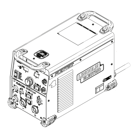
Construction
Flextec 350X Construction
Register your machine:
www.lincolnelectric.com/register
Authorized Service and Distributor Locator:
www.lincolnelectric.com/locator
Save for future reference
Date Purchased
Code: (ex: 10859)
Serial: (ex: U1060512345)
IM10570-B
|
Issue Date Aug - 23
© Lincoln Global, Inc. All Rights Reserved.
350XP & Flextec 350X
®
Flextec 350XP
®
For use with machines having Code Numbers:
Flextec® 350XP: 13067, 13071,
13578, 13579
Flextec® 350X Construction:
13066, 13070, 13073, 13532,
13581, 13582
Flextec® 350XP CE: 13461
Need Help? Call 1.888.935.3877
to talk to a Service Representative
Hours of Operation:
8:00 AM to 6:00 PM (ET) Mon. thru Fri.
After hours?
Use "Ask the Experts" at lincolnelectric.com
A Lincoln Service Representative will contact you
no later than the following business day.
For Service outside the USA:
Email: globalservice@lincolnelectric.com
Advertisement
Table of Contents

Subscribe to Our Youtube Channel
Related Manuals for Lincoln Electric Flextec 350XP CE


Summary of Contents for Lincoln Electric Flextec 350XP CE
- Page 1 Operator’s Manual Flextec 350XP & Flextec 350X ® ® Construction For use with machines having Code Numbers: Flextec 350XP Flextec® 350XP: 13067, 13071, 13578, 13579 Flextec® 350X Construction: 13066, 13070, 13073, 13532, 13581, 13582 Flextec® 350XP CE: 13461 Flextec 350X Construction Need Help? Call 1.888.935.3877 Register your machine: to talk to a Service Representative...
-
Page 2: Safety Depends On You
THANK YOU FOR SELECTING KEEP YOUR HEAD OUT OF THE FUMES. A QUALITY PRODUCT BY DON’T get too close to the arc. LINCOLN ELEC TRIC. Use corrective lenses if necessary to stay a reasonable distance away from the arc. READ and obey the Safety Data PLEASE EXAMINE CARTON AND EQUIPMENT FOR Sheet (SDS) and the warning label DAMAGE IMMEDIATELY... - Page 3 P.O. Box 351040, Miami, Florida 33135 or CSA Standard W117.2. A Free copy of “Arc Welding Safety” booklet E205 2.a. Electric current flowing through any conductor is available from the Lincoln Electric Company, 22801 causes localized Electric and Magnetic Fields (EMF). St. Clair Avenue, Cleveland, Ohio 44117-1199.
-
Page 4: Electric Shock Can Kill
SAFETY ELECTRIC SHOCK ARC RAYS CAN BURN. CAN KILL. 3.a. The electrode and work (or ground) circuits are 4.a. Use a shield with the proper filter and cover plates to protect your electrically “hot” when the welder is on. Do eyes from sparks and the rays of the arc when welding or not touch these “hot”... - Page 5 SAFETY WELDING AND CUTTING CYLINDER MAY EXPLODE IF SPARKS CAN CAUSE DAMAGED. FIRE OR EXPLOSION. 7.a. Use only compressed gas cylinders containing the correct shielding gas for the process used 6.a. Remove fire hazards from the welding area. If and properly operating regulators designed for this is not possible, cover them to prevent the welding sparks the gas and pressure used.
- Page 6 If any electromagnetic disturbances are detected the operator must put in place corrective actions to eliminate these disturbances with, if necessary, assistance from Lincoln Electric. This equipment does not comply with IEC 61000-3-12. If it is connected to a public low-voltage system, it is responsibility of the installer or user of the equipment to ensure, by consultation with the distribution network operator if necessary, that the equipment may be connected.
- Page 7 Maintenance of the Welding Equipment The welding equipment should be routinely maintained according to the manufacturer’s recommendations. All access and service doors and covers should be closed and properly fastened when the welding equipment is in operation. The welding equipment should not be modi ed in any way except for those changes and adjustments covered in the manufacturer’s instructions.
- Page 8 Efficiency when max power Name consumption / Idle power consumption Flextec 350XP CE 87.00% / 39W idle state, set the Weld Terminals to off and Local/Remote to remote and wait until the fan is off. The fan will be off when the units are powered up, or will turn off after a delay of (up to) 5 minutes if the welding output was just disabled.
- Page 9 Item Component Material for recovery Selective treatment Enclosure Steel Heat sink Aluminum Si, 11 g Mg, 18 g Enclosure Aluminum Si 6 g Mg 72 g Handle Aluminum Si, 118 g Mg, 1 g Output terminal Brass PC board Required Choke Copper Transformers...
- Page 10 FLEXTEC 350XP AND FLEXTEC 350X CONSTRUCTION TABLE OF CONTENTS ® ®...
-
Page 11: General Functional Description
FLEXTEC 350XP AND FLEXTEC 350X CONSTRUCTION GENERAL DESCRIPTION ® ® GENERAL DESCRIPTION RECOMMENDED PROCESSES Flextec 350XP is designed for CC-SMAW, CC-GTAW (Touch Start GENERAL FUNCTIONAL DESCRIPTION TIG™), CV-GMAW, CV-GMAW-P, CV-FCAW-SS, CV-FCAW-G. CAG arc gouging is also supported in the CV and CC modes. The Flextec 350XP and Flextec 350X Construction are inverter based, multi-process, DC power sources that have a 5 to 425 Amp output range. - Page 12 CrossLinc® compatible wire feeder or remote control. • Activ8x Pipe Compatible - The Flextec 350XP CE is compatible Synergic Pulse Welds. * Flextec 350XP and 350XP CE only...
-
Page 13: Common Equipment Packages
FLEXTEC 350XP AND FLEXTEC 350X CONSTRUCTION INSTALLATION ® ® INSTALLATION COMMON EQUIPMENT PACKAGES WARNING COMMON OPTIONAL KITS & ACCESSORIES ELECTRIC SHOCK can kill. K3059-4 INVERTER CART (REQUIRES LOCKING FOOT KIT) ONLY A QUALIFIED ELECTRICIAN SHOULD CONNECT THE INPUT LEADS TO THE K4424-1 350XP LOCKING FOOT KIT FLEXTEC MACHINE. -
Page 14: Input And Ground Connections
FLEXTEC 350XP AND FLEXTEC 350X CONSTRUCTION INSTALLATION ® ® INPUT AND GROUND CONNECTIONS HIGH FREQUENCY PROTECTION The Flextec 350XP comes standard with a power cord. Connect Locate the Flextec 350XP away from radio controlled machinery. the supply lines to 3 phase power and the ground according to The normal operation of the Flextec 350XP may adversely affect your local and national electrical codes. - Page 15 K4272-2 Flextec 350XP STANDARD - Tweco K3441-2 Flextec 350X CONSTRUCTION - Twist Mate K3442-2 Flextec 350XP - Twist Mate K4272-2-SB Flextec 350X CONSTRUCTION - Sunbelt K5422-1 Flextec 350XP CE - Twist Mate POWER SOURCES - INPUT VOLTAGE AND CURRENT INPUT VOLTAGE ± INPUT...
- Page 16 FLEXTEC ® 350XP AND FLEXTEC 350X CONSTRUCTION ® INSTALLATION PHYSICAL DIMENSIONS MODEL HEIGHT WIDTH DEPTH WEIGHT 74 LBS (33.6 KG) 17.0 IN (432 MM) 13.0 IN (330 MM) 27.0 IN (609 MM) All Models 79 LBS (35.8 KG) TEMPERATURE RANGES OPERATING TEMPERATURE STORAGE TEMPERATURE INSULATION CLASS...
- Page 17 FLEXTEC 350XP AND FLEXTEC 350X CONSTRUCTION INSTALLATION ® ® CASE FRONT CONTROL - STANDARD FIGURE A.1A 11. Wire Feeder Voltmeter: Polarity selection switch matches the 1. Amperage LCD Display polarity of the wire feeder voltmeter to the polarity of the Thermal LED: A yellow light that comes on when an over electrode.
- Page 18 FLEXTEC 350XP AND FLEXTEC 350X CONSTRUCTION INSTALLATION ® ® CASE FRONT CONTROL - CONSTRUCTION FIGURE A.1B 10. Output Control Dial: Sets the Output Current or Voltage for the 1. Amperage LCD Display selected Weld Process. Thermal LED: A yellow light that comes on when an over 11.
-
Page 19: Case Back Controls
FLEXTEC 350XP AND FLEXTEC 350X CONSTRUCTION INSTALLATION ® ® CASE BACK CONTROLS FIGURE A.2 1. USB-B Micro Connector: Remove cap and connect to computer to re-program machine software. Replace cap for environmental protection. 2. Input Cable: Comes with domestic and CE machines (not included for CCC model). - Page 20 FLEXTEC 350XP AND FLEXTEC 350X CONSTRUCTION INSTALLATION ® ® FIGURE A.3 - DIP SWITCH LOCATION ON USER INTERFACE PCB...
- Page 21 FLEXTEC 350XP AND FLEXTEC 350X CONSTRUCTION INSTALLATION ® ® ANALOG WIRE FEEDER CONNECTIVITY Picture Function Wiring GROUND TRIGGER, COMMON TRIGGER INPUT 77 REMOTE POTENTIOMETER, 5K 14-PIN 76 REMOTE POTENTIOMETER, WIPER CONNECTOR FOR WIRE 75 REMOTE POTENTIOMETER, COMMON FEEDER VOLTAGE SENSE (21) CONNECTIVITY.
-
Page 22: Recommended Electrode And Work Cable Sizes For Arc Welding
FLEXTEC 350XP AND FLEXTEC 350X CONSTRUCTION INSTALLATION ® ® RECOMMENDED ELECTRODE AND WORK CABLE SIZES FOR ARC WELDING (See Table A.1) Connect the electrode and work cables between the appropriate Tabulated below are copper cable sizes recommended for output studs of the Flextec 350XP per the following guidelines: different currents and duty cycles. -
Page 23: Remote Sense Lead Specifications
® ® REMOTE SENSE LEAD SPECIFICATIONS Genuine Lincoln Electric control cables should be used at all times (except where noted otherwise). Lincoln Electric cables are the Flextec 350XP. Most are designed to be connected end-to-end for ease of extension. Generally, it is recommended that the total length not exceed 100 feet (30.5 m). - Page 24 FLEXTEC 350XP AND FLEXTEC 350X CONSTRUCTION INSTALLATION ® ® CONNECTING LF-72 AND LF-74 TO THE FLEXTEC 350XP WIRE FEEDER 14-PIN CONTROL CABLE K1797-XX LF-72 FLEXTEC 350XP ELECTRODE LF-74 WORK CONTROL SETTING WELD MODE CV, CV-INNERSHIELD WELD TERMINALS REMOTELY CONTROLLED LOCAL REMOTE/LOCAL (REMOTE IF K2329-1 INSTALLED) VOLTMETER POLARITY...
- Page 25 FLEXTEC 350XP AND FLEXTEC 350X CONSTRUCTION INSTALLATION ® ® CONNECTING LN-10 AND DH-10 TO THE FLEXTEC 350XP WIRE FEEDER 14-PIN CONTROL CABLE K1501-XX LN-10 FLEXTEC 350XP DH-10 ELECTRODE WORK CONTROL SETTING WELD MODE CV, CV-INNERSHIELD WELD TERMINALS REMOTELY CONTROLLED REMOTE/LOCAL REMOTE VOLTMETER POLARITY PROCESS DEPENDENT...
- Page 26 INSTALLATION FLEXTEC 350XP AND FLEXTEC 350X CONSTRUCTION ® ® CONNECTING LN-15 (K1870-1) TO THE FLEXTEC 350XP WIRE FEEDER LN-15 FLEXTEC 350XP ELECTRODE (K1870-1) WORK CLIP WORK CONTROL SETTING WELD MODE CV, CV-INNERSHIELD WELD TERMINALS REMOTE/LOCAL LOCAL VOLTMETER POLARITY PROCESS DEPENDENT CONNECTING LN-15 (K1871-1) TO THE FLEXTEC 350XP WIRE FEEDER 14-PIN CONTROL CABLE K1819-XX...
- Page 27 FLEXTEC 350XP AND FLEXTEC 350X CONSTRUCTION INSTALLATION ® ® CONNECTING ACTIV8, ACTIV8X, LN-25 PRO SERIES, LN-25 PIPE, LN-25 IRONWORK AND LN-25X TO THE FLEXTEC 350XP WIRE FEEDER LN-25 PRO LN-25 Pipe LN-25 Ironworker FLEXTEC 350XP ELECTRODE LN-25X, Activ8X WORK CLIP WORK CONTROL SETTING WELD MODE...
- Page 28 CONTROL SETTING WELD MODE ARCLINK WELD TERMINALS REMOTE N.A. REMOTE/LOCAL N.A. VOLTMETER POLARITY N.A. CONNECTING ACTIV8X PIPE TO FLEXTEC 350XP CE ACTIV8X PIPE FLEXTEC 350XP CE WORK CONTROL SETTING WELD MODE NOT ARCLINK OR TIG WELD TERMINALS N.A. REMOTE/LOCAL N.A.
- Page 29 OPERATION FLEXTEC 350XP AND FLEXTEC 350X CONSTRUCTION ® ® OPERATION POSITIVE OUTPUT SAFETY PRECAUTIONS NEGATIVE OUTPUT WARNING 3 PHASE INVERTER ELECTRIC SHOCK can kill. • UNLESS USING COLD FEED FEATURE, WHEN FEEDING WITH GUN TRIGGER, THE ELECTRODE INPUT POWER AND DRIVE MECHANISM ARE ALWAYS ELECTRICALLY ENERGIZED AND COULD REMAIN ENERGIZED SEVERAL SECONDS AFTER THE WELDING CEASES.
-
Page 30: Power-Up Sequence
OPERATION FLEXTEC 350XP AND FLEXTEC 350X CONSTRUCTION ® ® POWER-UP SEQUENCE MAKING A WELD When power is applied to the Flextec 350XP, the displays will The Flextec 350XP is a multi-process inverter welder. The Weld illuminate and the machine electronics will complete a power up Process Selector Switch is used to set the desired weld mode. -
Page 31: Synergic Welding Modes
FLEXTEC 350XP AND FLEXTEC 350X CONSTRUCTION OPERATION ® ® Volt Display Meter DEFINITION OF WELDING MODES meter displays desired preset voltage NON-SYNERGIC WELDING MODES value (+/- .1V). • A Non-synergic welding mode requires all welding process • Prior to STICK or TIG operation, the meter variables to be set by the operator. - Page 32 FLEXTEC 350XP AND FLEXTEC 350X CONSTRUCTION OPERATION ® ® Thermal Light This status light indicates when the power source has been driven into thermal overload. If the output terminals were "ON", the output will be turned back on once the unit cools down to an acceptable temperature level.
-
Page 33: Basic Modes Of Operation
FLEXTEC 350XP AND FLEXTEC 350X CONSTRUCTION OPERATION ® ® Amperage Display – This display will display the pre-set welding current when the machine is in the idle state. After welding, the BASIC MODES OF OPERATION meter holds the actual amperage value for 5 seconds. Output adjustment while in the "hold"... - Page 34 FLEXTEC 350XP AND FLEXTEC 350X CONSTRUCTION OPERATION ® ® SMAW Amperage Display – This display will display the pre-set welding current when the machine is in the idle state. After welding, the This weld mode is a constant current (CC) mode featuring meter holds the actual amperage value for 5 seconds.
- Page 35 FLEXTEC 350XP AND FLEXTEC 350X CONSTRUCTION OPERATION ® ® CV-Gas Amperage Display – This display will display three dashed lines when the machine is in the idle state. This indicates that This weld mode is a constant voltage (CV) mode featuring amperage is not settable in this weld mode.
- Page 36 OPERATION FLEXTEC 350XP AND FLEXTEC 350X CONSTRUCTION ® ® CV-Innershield CrossLinc® - CrossLinc is a new welding system communication technology. When using a CrossLinc enabled power source such This weld mode is a constant voltage (CV) mode featuring as the Flextec 350XP and a CrossLinc enabled wire feeder such as continuous control from 10 to 45 volts.
- Page 37 When ECO Mode is active the remote or feeder is turned off by the “weld terminals” the Flextec 350XP CE's weld and auxiliary power outputs are switch on the front panel of the Flextec, the active process will disabled.
- Page 38 DC welding power source and the work clamp. Weld Fume Control Solutions. Lincoln Electric offers a wide variety of welding fume control solutions, ranging from portable systems easily wheeled around the shop to shop-wide central systems servicing many dedicated welding stations.
-
Page 39: Current Calibration
FLEXTEC 350XP AND FLEXTEC 350X CONSTRUCTION MAINTENANCE ® ® MAINTENANCE CURRENT CALIBRATION WARNING 1. Connect the resistive load bank and test voltmeter to the welding output terminals. 2. Put dipswitch 1 in the on position. 3. Rotate the Hot Start knob and Arc Control knob to the Before carrying out service, maintenance and/or minimum. - Page 40 FLEXTEC ® 350XP AND FLEXTEC 350X CONSTRUCTION ® MAINTENANCE TO RESTORE FACTORY CURRENT CALIBRATION 3. Remove 2 fasteners holding lter bracket to case bottom. See FIGURE D.2. 1. Connect the resistive load bank and test voltmeter to the welding output terminals. FIGURE D.2 2.
- Page 41 FLEXTEC ® 350XP AND FLEXTEC 350X CONSTRUCTION ® MAINTENANCE 7. Remove input cord by loosening cable strain relief on case back. See FIGURE D.4. FIGURE D.4 8. Replace input cord with desired cord by connecting 3 input voltage phase leads to B1, B2, and B3 on EMI Filter board. Secure ground lead to lug on case bottom.
- Page 42 ® TROUBLESHOOTING WARNING Service and Repair should only be performed by Lincoln Electric Factory Trained Personnel. Unauthorized repairs performed on this equipment may result in danger to the technician and machine operator and will invalidate your factory warranty. For your safety and to avoid Electrical Shock, please observe all safety notes and precautions detailed throughout this manual.
- Page 43 Observe all Safety Guidelines detailed throughout this manual PROBLEM POSSIBLE CAUSE RECOMMENDED COURSE OF ACTION Major physical or electrical 1. Contact your local authorized Lincoln Electric damage is evident when the Field Service facility for technical assistance. sheet metal covers are removed.
-
Page 44: Using The Status Led To Troubleshoot System Problems
TROUBLESHOOTING FLEXTEC 350XP AND FLEXTEC 350X CONSTRUCTION ® ® Observe all Safety Guidelines detailed throughout this manual The status lights on the User Interface board, Crosslinc®, Input USING THE STATUS LED TO TROUBLESHOOT board, Control board and the Switch board are dual-color LED’s or SYSTEM PROBLEMS green LEDs. - Page 45 TROUBLESHOOTING FLEXTEC 350XP AND FLEXTEC 350X CONSTRUCTION ® ® ERROR DESCRIPTION POSSIBLE CAUSE CORRECTIVE ACTION CODE# DC Link Capacitor Over/Under The voltage on the main DC link Verify all three phases of the AC input are connected Voltage capacitors housed on the switchboard has either gone too high or too low If for any reason you do not understand the test procedures or are unable to perform the tests/repairs safely, contact your Lincoln Authorized Service Facility for technical troubleshooting assistance before you proceed.
- Page 46 FLEXTEC 350XP AND FLEXTEC 350X CONSTRUCTION DIAGRAMS ® ® WIRING DIAGRAM - CODE 13067, 13069, 13071...
- Page 47 FLEXTEC ® 350XP AND FLEXTEC 350X CONSTRUCTION ® DIAGRAMS WIRING DIAGRAM - CODE 13066, 13070, 13073, 13580, 13581, 13582...
- Page 48 FLEXTEC 350XP AND FLEXTEC 350X CONSTRUCTION DIAGRAMS ® ® WIRING DIAGRAM - CODE 13461...
- Page 49 FLEXTEC 350XP AND FLEXTEC 350X CONSTRUCTION DIAGRAMS ® ® DIMENSIONAL PRINT 26.70 13.32 23.92 TOP VIEW 16.59 3.14 17.90 1/4-20 THREAD .50 MAX DEPTH 3.70 (4 PLACES) 4.23 BOTTOM VIEW...
- Page 50 Do not touch electrically live parts or Keep flammable materials away. Wear eye, ear and body protection. WARNING electrode with skin or wet clothing. Insulate yourself from work and ground. Spanish No toque las partes o los electrodos Mantenga el material combustible Protéjase los ojos, los oídos y el AVISO DE bajo carga con la piel o ropa moja-...
- Page 51 Keep your head out of fumes. Turn power off before servicing. Do not operate with panel open or Use ventilation or exhaust to guards off. WARNING remove fumes from breathing zone. Spanish Los humos fuera de la zona de res- Desconectar el cable de ali- No operar con panel abierto o AVISO DE...
- Page 52 Lincoln Electric is solely within the control of, and remains the sole responsibility of the customer. Many variables beyond the control of Lincoln Electric affect the results obtained in applying...
Need help?
Do you have a question about the Flextec 350XP CE and is the answer not in the manual?
Questions and answers