
Related Manuals for Eaton Vickers V Series


Summary of Contents for Eaton Vickers V Series
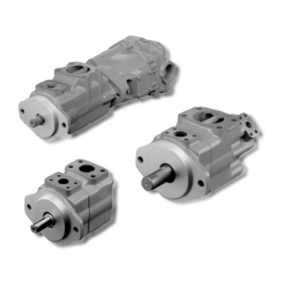
- Page 1 ® Vickers Vane Pumps V Series - Low Noise Vane Pumps High Performance Intravane Pumps For Industrial Applications Revised 6/95...
- Page 2 Introduction D Twelve vane system provides low Vickers offers the most complete line of hydraulic intravane pumps for industrial amplitude flow pulsations resulting in applications. A wide variety of single low system noise characteristics. and multiple configurations enables you D Hydraulic balancing, designed to to select the precise pump or prevent internally-induced radial shaft combination best suited for your...
-
Page 3: Table Of Contents
Table of Contents Model Maximum Rated Maximum Geometric Speed Pressure Displacement r/min bar (psi) /r (in Single Pumps Installation 45 (2.8) 1800 207 (3000) ... . 67 (4.1) 1800 172 (2500) . -
Page 4: Performance Data
Performance Data Single, Double & Thru-Drive Vane Pumps Pressure limits, inlet port - bar (psi): Minimum 0,17 bar (5" Hg) for anti wear oil 0,10 bar (3" Hg) for water containing fluids and phosphate esters Maximum 1,4 bar (20 psi) all fluids Range 0 to 0,35 bar (0 to 5 psi) all fluids Maximum continuous pressures in bar (psi), outlet ports... -
Page 5: Model Codes
Single Pump Model Code Model Code F3 - Viton Seals Geometric Displacement Mounting Omit if not required Rated capacity (USgpm) at 1200 rpm, Omit - Flange mounting 6,9 bar (100 psi) F - Foot mounting Series Designation Frame Code Shafts Size (USgpm) 20V -... - Page 6 Double Pump Model Code Model Code F3 - Viton Seals Port Connections Port Orientation A - SAE 4-bolt flange (Viewed from cover end of pump) Omit if not required All series except 2525V & 4535V With No.1 outlet opposite inlet: Port Connection Modifier Series Designation AA - No.
- Page 7 Thru-Drive Pump Model Code Model Code F3 - Viton Seals Port Connections Outlet Postions Omit if not required A - SAE 4-bolt flange (Viewed from cover end of pump) A - Opposite end B - 90_ CCW from inlet Series Designation Port Connection Modifier C - Inline with inlet 25VT - 33 to 67 cm...
-
Page 8: Operating Data
Operating Data Sound Levels Water-in-oil Emulsions Air Bleed Average sound levels are at 138 bar Water-in-oil emulsions may be used. At the time of first-starting, if the pump (2000 psi) using SAE 10W (26 cSt) – However, they require careful selection does not immediately prime, air should (128 SUS) oil at 50_C (120_F). -
Page 9: Application Data
Application Data contacting Vickers, Incorporated. Vickers products, as any components, Fluid Cleanliness Recommendations on filtration and the will operate with apparent satisfaction in Proper fluid condition is essential for selection of products to control fluid fluids with higher cleanliness codes than long and satisfactory life of hydraulic condition are included in 561. -
Page 10: 20V Performance Characteristics
20V Performance Characteristics 20V Cartridge Performance Typical flows at 50°C (120°F), 10W oil (26cSt) - (128 SUS), 0 psi inlet at specified speeds Codes 5 and 12 Displacement bar (psi) Code 80 (21.13) 7 (100) 70 (18.49) 70 (1000) 160 (2300) 60 (15.85) 50 (13.21) 40 (10.58) - Page 11 20V Performance Characteristics 20V Cartridge Performance Typical flows at 50°C (120°F), 10W oil (26cSt) - (128 SUS), 0 psi inlet at specified speeds Codes 2 and 9 Displacement bar (psi) Code 61 (16.0) 7 (100) 53 (14.0) 70 (1000) 160 (2300) 207 (3000) 45 (12.0) 38 (10.0)
- Page 12 20V Performance Characteristics Codes 8, 11, and 14 Displacement bar (psi) Code 90 (23.78) 7 (100) 80 (21.13) 70 (1000) 140 (2000) 70 (18.49) 7 (100) 70 (1000) 140 (2000) 60 (15.85) 210 (3000) 50 (13.21) 7 (100) 70 (1000) 140 (2000) 210 (3000) 40 (10.58)
- Page 13 25V(T), 25**V, & **25V Performance Characteristics 25V(T), 25**V, and **25V Code 10 Displacement Codes 12 and 17 Displacement bar (psi) bar (psi) Code (20.0) (26.42) 7 (100) 70 (1000) 140 (2000) 170 (2500) 7 (100) (16.0) (21.13) 70 (1000) 7 (100) 140 (2000) 70 (1000) 207 (3000)
- Page 14 25V(T), 25**V, & **25V Performance Characteristics Codes 14 and 21 Displacement bar (psi) Code 120 (31.70) 7 (100) 70 (1000) 140 (2000) 170 (2500) 100 (26.42) 80 (21.13) 7 (100) 70 (1000) 140 (2000) 170 (2500) 60 (15.85) 40 (10.58) 20 (5.28) 1200 1600...
- Page 15 35V(T), 35**V, & **35V Performance Characteristics 35V(T), 35**V, and **35V Codes 25 and 35 Displacement bar (psi) Code 200 (52.84) 7 (100) 70 (1000) 140 (2000) 170 (2500) 180 (47.55) 160 (42.27) 7 (100) 140 (36.99) 70 (1000) 140 (2000) 170 (2500) 120 (31.70) 100 (26.42)
- Page 16 35V(T), 35**V, & **35V Performance Characteristics Codes 30 and 38 Displacement bar (psi) Code 7 (100) 70 (1000) 140 (2000) 200 (52.84) 170 (2500) 180 (47.55) 7 (100) 70 (1000) 160 (42.27) 140 (2000) 170 (2500) 140 (36.99) 120 (31.70) 100 (26.42) 80 (21.13) 60 (15.85)
- Page 17 45V(T), 45**V Performance Characteristics 45V(T) and 45**V Codes 42 and 60 Displacement Code 45 Displacement bar (psi) Code bar (psi) (95.10) (80.0) 7 (100) 70 (1000) 7 (100) 140 (2000) 70 (1000) (84.54) (70.0) 170 (2500) 140 (2000) 170 (2500) (73.97) (60.0) 7 (100)
- Page 18 45V(T), 45**V Performance Characteristics Code 50 Displacement bar (psi) Code 360 (95.10) 320 (84.54) 7 (100) 280 (73.97) 70 (1000) 140 (2000) 170 (2500) 240 (63.40) 200 (52.84) 160 (42.27) 120 (31.70) 80 (21.13) 40 (10.58) 1200 1600 2000 SPEED - RPM Code 50 Input bar (psi) Code...
-
Page 19: 45 (2.8) 1800 207 (3000)
20V Installation Dimensions 20V Series Single Pumps Millimeters (inches) 22,2 35,7 2,36 (.875) (1.41) (.093) 1,11 17,9 .375-16 UNC-2B or M10-.750 thd., 4 holes (.44) (.07) Uses FL1-6 series flange. 23,8 (.94) 101,6 (4.00) ∅ 101,5 (3.99) (2.75) 34,9 (1.38) 47,6 (1.87) ∅... -
Page 20: 67 (4.1) 1800 172 (2500)
25V, 35V, 45V Installation Dimensions 25V, 35V and 45V Single Pumps Millimeters (inches) Outlet ∅C, SAE flange pad with 4 mounting holes. ∅F: ∅K 25V pumps use FL-8 flange 35V pumps use FL-10 flange 45V pumps use FL-12 flange ∅F Inlet ∅G, SAE flange pad with four mounting holes. -
Page 21: 2520V 67 (4.1) Shaft End 1800 172 (2500)
2520V, 35**V, 452*V Installation Dimensions 2520V, 35**V and 452*V Double Pumps Millimeters (inches) Inlet ∅H For shaft options see pages 29 & 30. E ∅F Outlet No. 2 ∅K Outlet No. 1 ∅D G See port flange kits and mountigs for double pumps on page 23. -
Page 22: 2525V 67 (4.1) Shaft End 1800 172 (2500)
2525V, 4535V Installation Dimensions 2525V and 4535V Series Double Pumps Millimeters (inches) G See port flange kits and mountigs for double pumps on the next page. ∅F Outlet No. 1 1.31” -12 UNC-2B str. thds. Outlet No. 2 ∅K Inlet ∅H Outlet No. - Page 23 Port Flange Kits / Mtg for Double Pumps G Port Flange Kits and Mountings for Double Pumps Inlet Outlet No. 1, Shaft end Outlet No. 2, Rear end Mounting Bolt Tap Mounting Bolt Tap Mounting Bolt Tap & Full Thread &...
-
Page 24: 25Vt 67 (4.1) 1800 172 (2500)
**VT Thru Drives Installation Dimensions **VT Series Thru Drives Conforms to SAE J744 For metric pilot flanges see page 31. Flange code 101 2 for 25VT Flange code 127 2 for 35VT & 45VT ∅X Inlet port ∅H ∅Z Outlet port For shaft options see pages 29 &... -
Page 25: Thru Drive Rear Mountings
**VT Thru–Drive Rear Mountings Installation Dimensions **VT Thru Drive Rear Mountings A" Rear Mounting A" To mounting flange 133,2 face (5.25) 6,53 66,6 (.257) (2.62) 1,45 .375 18 UNC 2B (.057) thd. 21,59 (.850) thru flange 2 holes (inch threads) 82,63 Ø... - Page 26 **VT Thru–Drive Rear Mountings Installation Dimensions **VT Thru Drive Rear Mountings B" Rear Mounting .500 13 Output UNC 2B thd. coupling 19,30 (.760) 174,8 Ø 13T 16/32 thru flange 2 (6.88) A" DP Spline To mounting flange face holes (inch threads) 9,78 (.385)
- Page 27 **VT Thru–Drive Rear Mountings Installation Dimensions **VT Thru Drive Rear Mountings BP" Rear Mounting Output coupling 174,8 13T 16/32 Ø A" (6.88) To mounting flange face DP Spline 10,16 (.400) Snap ring 66,7 (2.62) 101,68 Ø (4.003) 63,5 (2.50) 133,4 (5.25) 84,1 (3.31)
- Page 28 **VT Thru Drive Rear Mountings Installation Dimensions **VT Thru Drive Rear Mountings C" Rear Mounting 212,9 Ø (8.38) 180.98 (7.125) A" 90,49 To mounting flange face (3.56) 13,2 (.52) .625 11 UNC 2B thd. 36,78 (1.45) thru flange 2 holes (inch threads) 127,08 Ø...
-
Page 29: Optional Shafts
Optional Shafts Straight Key Shafts Thru-drive shafts, see pages 32. ∅D 1,5 (.06) x 45_ Pump Shaft F key width ∅D Code x length 59 (2.32) 9,53 (.375) 12,1 (.476) 22,23 (.875) 24,5 (.966) 4,75 (.817) 22,20 (.874) 24,4 (.961) x 32 (1.25) 59 (2.32) 9,53 (.375) - Page 30 Optional Shafts Splined Shafts ∅E See spline data table below Pump Shaft Spline Data ∅E Code (see below) 41,1 (1.62) 9,53 (.375) 11,1 (.437) 3,9 (.156) 27,8 (1.09) 44,5 (1.75) 9,53 (.375) 11,1 (.437) 3,9 (.156) 27,8 (1.09) 2520V 2525V 59,9 (2.36) 9,53 (.375) 17,3 (.68)
-
Page 31: Iso Pilot Flange Mounting Options
Optional Shafts Optional ISO 3019/2 Metric Pilot Flange Mounting Options for “VM” & “VT*M” Pumps Pilot diameter 25 and 35 Size Pumps Model ØB ØC Pilot diameter 25VM Single Pumps 14,27 100,0 (3.937) 25VT*M Thru-drive Pumps (.562) (5.51) (6.87) 99,95 (3.935) 25**VM Double Pumps ØB 35VM Single Pumps... -
Page 32: Torque Loading & Drives
Torque Loading for Direct Drives Table 1 Single pumps (not thru–drive models) Example: All listed shafts are satisfactory up to Single & Double Pumps Shaft A 3525V38A17 pump operating at 172 maximum pressures in “Pressure and bar (2500 psi) front section and 138 bar Torque Ratings speed limits”... - Page 33 Drives Recommended Drives Mounting Dimensions Vickers units are designed for use on Requirements direct coaxial drives using spline Dimensional control requirements of the connections and/or flexible couplings. customer’s mounting pad to which the If drives imposing radial and/or axial pump or motor is affixed are as follows. loads, or key drives are being considered, consult your Vickers Pilot Diameter...
-
Page 34: Foot Mounting Bracket Option
Foot Mounting Bracket Option (Not suitable for thru drive pumps) Bolts for mounting pump are supplied with bracket. ØL Pump mounting surface ØN ØP ØL Part No. 422583 17,4 (6.75) (7.00) (3.625) (7.125) (3.656) (3.858) (.687) (.50) (5.750) 422584 109,5 (10.43) (8.37) (4.312) -
Page 35: Weights & Mounting Options
Application Data Moment of Inertia Mounting Options Service Information Mounting attitude of all pumps is Refer to specific Vickers part drawing or Model Nm/sec Moment unrestricted except for any limitations in overhaul manual (below) for service lb in sec respect to rear-end pumps to be titled to information or consult your Vickers 0,000757 (.00670)
Need help?
Do you have a question about the Vickers V Series and is the answer not in the manual?
Questions and answers