Eaton
®
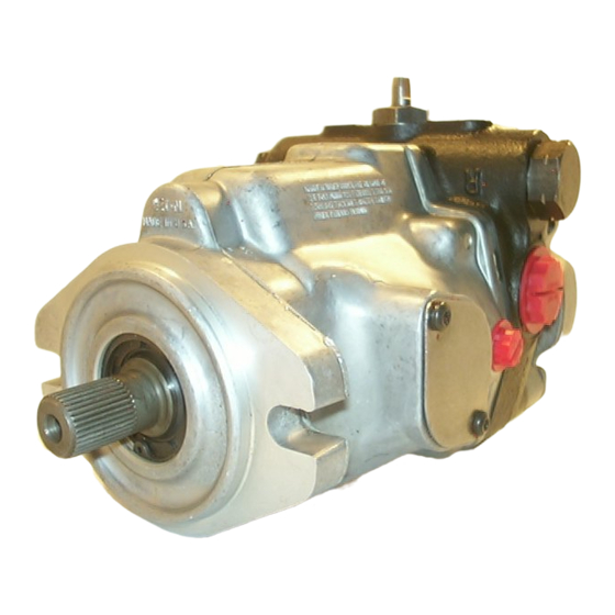
Medium Duty Piston Pump
Repair Information
Model 70142 / 70144,
and 70145,
23.6 cm
Variable Displacement Piston Pump
with
20.3 cm
3
/r [1.24 in
3
/r [1.44 in
3
/r] Displacement
Valve Plate
3
/r] Displacement
design code
No. 7-623
July,1995
01 02


Need help?
Do you have a question about the 70142 and is the answer not in the manual?
Questions and answers