Advertisement
Table of Contents
- 1 Table of Contents
- 2 Introduction
- 3 Identification
- 4 Required Tools
- 5 Exploded View Drawing
- 6 Parts List
- 7 Disassembly and Inspection
- 8 Reassembly
- 9 Appendix A: Charge Pump Adapter Assembly
- 10 Appendix B: Manual Servo Control Basic Assembly
- 11 Appendix C: Rotating Kit Assembly
- 12 Fault-Logic Trouble Shooting
- 13 Start-Up Procedure
- Download this manual
Advertisement
Table of Contents

Related Manuals for Eaton 72400


Summary of Contents for Eaton 72400
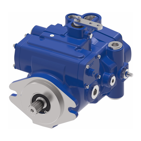
- Page 1 Eaton ® Medium Duty Piston Pump Repair Information Model 72400 Servo Controlled Piston Pump v-04...
-
Page 2: Table Of Contents
Start-up Procedure .................... Introduction This manual provides service information for the Eaton Model 72400 Servo Controlled Piston Pumps. Step by step instructions for the complete disassembly, inspection, and reassembly of the pump are given. The following recommendations should be followed to insure successful repairs. -
Page 3: Identification
Stamped on each unit. 7 2 4 0 0 - 0 0 1 - 0 4 A - Product Number Discription 72400 = Single Piston Pump 78461 = Tandem Piston Pump 78462 = Single Piston Pump with Gear Tandem Pumps - Product Number... -
Page 4: Exploded View Drawing
Drawing - Figure 1-1 28-3 28-4-3 28-3-1 28-6 38-1 28-4 28-4-1 28-5 28-4-2 40-1 Left Side 39-1 Serial Code and 28-6 Product Number Location 41-1 28-2 Right Side 28-1 Shaft assembly for rear pump of tandem. © Copyright 1999 Eaton Corporation... - Page 5 Model 72400 Parts Drawing - Figure 1-1 K1-3 21-1 K1-4 K1-1 K1-2 29-2 29-1 57-1 22-1 K2-1 21-1 29-2 Inner Gerotor 11 tooth Coupler 29-1 57-1 22-1 Valve Plate Identification Note "V" notch locations Lefthand Righthand Rotation Rotation...
-
Page 6: Parts List
Model 72400 Parts List Item Qty. Description Jam Nut Retaining Ring Retaining Ring Seal Washer Cap Screw, #10-24, 25,4mm [1.0 in.] Long Rotating Kit Assenbly Servo Piston Assembly Servo Piston Follower Cover Plate Cover Plate Gasket Housing Gasket Control Housing Gasket... - Page 7 Includes Items 32 and 35 K2-1 Washer Cover Plate Kit for "A" SAE Flange Series 82-2 Mount Includes Items 32, 35, and 44 72400-908, Seal Repair Kit for single pumps (Two Required for Tandem Units) Parts included in 72400-908 Seal Repair Kit...
-
Page 8: Disassembly And Inspection
Model 72400 Disassembly Disassembly - Servo Controlled Piston Pump The following instructions apply to a single servo controlled Remove housing gasket from housing or endcover. piston pump with or without a gerotor charge pump. A tandem With pump still in vise, remove the six cap screws retaining pump assembly should be separated into individual pumps the manual servo control assembly. -
Page 9: Reassembly
Model 72400 Disassembly and Reassembly Housing Inspection: centering the servo piston assembly is required. Measure in from the left side and set servo piston 12,7 mm [.5 in.] from • Check the bearing (press fit) in housing. If needles surface of housing servo bore as shown in figure 1-5. - Page 10 Model 72400 Reassembly Refer to Appendix C for reassembly of rotating kit assembly. 20 Retain endcover and adapter plate (when used) with four cap screws, Torque 37 to 42 N•m [27 to 31 lbf•ft]. 11 To install rotating kit assembly, leave housing and shaft in the horizontal position.
-
Page 11: Appendix A: Charge Pump Adapter Assembly
Model 72400 Appendix A - Charge Pump Adapter Assembly Disassembly - Charge Pump Adapter Assembly Remove plug, shims, spring, and poppet from adapter assembly. Inspection: • Inspect the charge pump relief valve seat inside the charge pump adapter. Check to insure that seat is smooth and free of burrs or other defects. -
Page 12: Appendix B: Manual Servo Control Basic Assembly
Model 72400 Appendix B - Manual Servo Control Basic Assembly Disassembly - Reassembly - Manual Servo Control Assembly Manual Servo Control Assembly Remove wiper seal with screw driver. Remove set screw Install spring retainer, spring, and second spring retainer retaining input shaft and remove input shaft from control onto spool. - Page 13 Model 72400 Appendix B - Manual Servo Control Basic Assembly 48-2 48-3 48-5 Figure 2-2 48-6 48-5 Wiper Seal 48-16 48-7 48-4 Metering Notches 48-15 48-14 48-1 Metering Notches Figure 2-1 Wide Band Neutral Spool Identification Mark 48-8 48-12 Item Qty.
- Page 14 Model 72400 Appendix B - Manual Servo Control Assembly Options Disassembly - Destroke Valve Assembly Option Remove the two cap screws and lock washers from manifold. Removing destroke valve assembly and two o-rings. Remove destroke valve from manifold in order to remove o-rings and back-up washers.
- Page 15 Model 72400 Appendix B - Manual Servo Control Assembly Options Disassembly - Disassembly - Neutral Lockout Switch Assembly Option Neutral Detent Option Loosen set screw in adapter and remove neutral lockout Loosen seal nut and remove ball plunger from control switch from adapter.
-
Page 16: Appendix C: Rotating Kit Assembly
Model 72400 Appendix C - Rotating Kit Assembly Disassembly - Rotating Kit Assembly Disassembly of rotating assembly is required for inspection only. Remove the nine piston assemblies, shoe retainer, and shoe retainer pivot from cylinder barrel. Item Qty. Description Piston assemblies... -
Page 17: Fault-Logic Trouble Shooting
Model 72400 Fault - Logic Trouble Shooting Explanatory Diagram This fault - logic trouble shooting guide is a diagnostic aid in Symptom: locating transmission problems. Action Match the transmission symptoms with the problem statements Step and follow the action steps shown in the box diagrams. This will... - Page 18 Model 72400 Fault - Logic Trouble Shooting Symptom: Neutral Difficult or Impossible to Find Inspect Inspect Inspect Replace External Control Valve Servo piston Pump Control Linkage Defective Defective Defective Repair Repair Repair Replace Replace Replace Symptom: System Operating Hot Inspect Heat...
- Page 19 Model 72400 Fault - Logic Trouble Shooting Symptom: Operates in One Direction Only Inspect Inspect Inspect Replace External System Control Valve Pump Control Linkage Relief Valves Defective Defective Defective Repair Repair Repair Replace Replace Replace Symptom: System Response Sluggish Check...
- Page 20 Model 72400 Fault - Logic Trouble Shooting Symptom: System Will Not Operate in Either Direction Check External Check Inspect Check Control Oil Level in Bypass Valve Charge Linkage Reservoir (If used) Pressure Defective Defective Below Level Fill to Repair Repair...
- Page 21 Model 72400 Fault - Logic Trouble Shooting Diagram Action Step Comments Inspect External Control Linkage for: 10 Check System Pressure: a. misadjusted or disconnected a. See figure 3-1 for location of pressure gauge installation b. binding, bent, or broken b. consult owner/operators manual for maximum system...
-
Page 22: Start-Up Procedure
Fill the reservoir with an approved oil that has been filtered The machine is now ready to be put into operation. through a 10 micron filter. Refer to Eaton Hydraulics Technical Data sheet number 3-401 titled Hydraulic Fluid 10 Frequent filter changes are recommended for the first two Recommendations. - Page 23 Model 72400 Notes...
- Page 24 Order parts from number 06-06-642 Parts Information booklet. Each order must include the following information. 1. Product and/or Part Number 2. Serial Code Number 3. Part Name 4. Quantity...
- Page 25 Shanghai 200021 Tel: +41 (0) 21 811 4600 China Tel: 952-937-9800 Tel: 86-21-6387-9988 Fax: 952-294-7722 Fax: +41 (0) 21 811 4601 Fax: 86-21-6335-3912 www.eaton.com/hydraulics © 2009 Eaton Corporation All Rights Reserved Printed in USA Document No. E-PUPI-TS015-E Supersedes 07-06-629 March 2009...
Need help?
Do you have a question about the 72400 and is the answer not in the manual?
Questions and answers