
Related Manuals for Eaton Vickers 2520V-20-282 Series


Summary of Contents for Eaton Vickers 2520V-20-282 Series
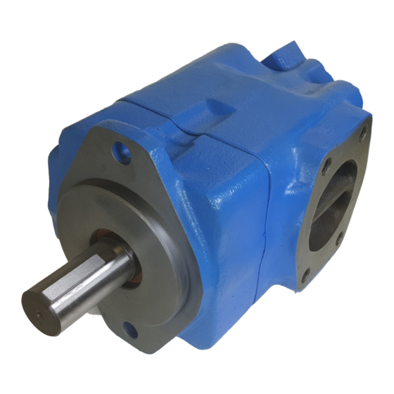
- Page 1 ® Vickers Overhaul Manual Vane Pumps Quiet Intra-Vane Type Double Pumps 2520V, 3520V, 3525V, 4520V, 4525V & 4535V Series -20 Design 282/283 Suffix Revised 07-01-86 I–3155–S...
-
Page 2: Table Of Contents
Table of Contents Section Page Introduction A. Purpose of Manual ............... . . B. -
Page 3: Purpose Of Manual
Section I – Introduction A. Purpose of Manual Model Parts Drawing Installation Drawing 2520V I-3186-S 504000 This manual describes operational characteristics and over- haul information for fixed and variable delivery inline piston 3520V I-3180-S 504300 type pumps and motors. The information contained herein 3525V I-3187-S 504500... -
Page 4: Description
Section II – Description A. General The double intra-vane pump with a 282/283 suffix is designed to operate at reduced noise levels, but still maintain the same reliability, operating characteristics and service advantages of previous models. All sound reduction in the 282/283 series pump is accomplished within the cartridge kit. -
Page 5: Installation And Operating Instructions
Section IV – Installation and Operating Instructions A. Installation Drawings NOTE For information on pickling, refer to instruction The installation drawings listed in Table 1 show operating sheet 1221-S. characteristics, installation dimensions and port locations. 2. To minimize flow resistance and the possibility of B. -
Page 6: Sound Levels
F. Sound Levels G. Overload Protection Although system noise levels can be reduced by modifying Relief valve limit pressure in the system to a prescribed pump design, fluid conditions also play a major part in maximum and protect components from excessive pressure. reducing system noise levels. -
Page 7: Product Life
Substitutes may result in early failure. Part numbers are Sealing Ring Rotor, vane and shown in the parts drawings listed in Table 1. intra-vane Back-up assembled Repair Kits – Commonly replaced parts are usually provided Ring inside ring and O-ring in the form of a kit (Figure 4). -
Page 8: Overhaul
Section VI – Overhaul A. Service Tools B. Unit Removal Standard Tools WARNING 1. One torque wrench with short extension and sockets. Select appropriate torque wrench according to cover screw Turn off all electrical power and relieve hydraulic specifications noted in Tables 4 and 5. pressure. -
Page 9: Cleaning
11. Pull the shaft group (items 32 through 34) from body F. Assembly (38). If bearing 933) or shaft (34) need replacement, remove retaining ring (32) with retaining ring pliers. Remove bearing Refer to the parts and service drawing listed in Table 1 for (33) from shaft (34) by using an arbor press. -
Page 10: Start-Up And Test
c. Make sure “O” ring (22) and back-up ring (21) are c. Make sure “O” ring (9) and back-up ring (8) are assembled correctly. Position as shown in Figure 8. Apply a assembled in the correct position (Figure 8). small amount of system fluid to screws (24) and thread NOTE screws into cartridge kit. - Page 11 31 32 22 21 35 37 Item Description Item Description Screw Cartridge Kit (items 21-30) Mounting Bracket Back-up Ring “O” Ring Screw Sealing Ring Cover Screw Cartridge Kit (items 7-17) Inlet Support Plate “O” Ring Back-up Ring Ring “O” Ring Rotor Sealing Ring Vanes &...
- Page 12 46 New Lane, Havant Eden Prairie, MN 55344 Hampshire PO9 2NB Telephone: 612 937-7254 England Fax: 612 937-7130 Telephone: (44) 170-548-6451 www.eatonhydraulics.com Fax: (44) 170-548-7110 Form No. 00-000 Copyright Eaton Corporation, 0000 All rights reserved. Printed in U.S.A Printed in U.S.A.
Need help?
Do you have a question about the Vickers 2520V-20-282 Series and is the answer not in the manual?
Questions and answers