
Related Manuals for Eaton Vickers 25V Series


Summary of Contents for Eaton Vickers 25V Series
- Page 1 ® Vickers Service Data Vane Pumps Quiet Intra-Vane Single Pumps 25V(T)-35V(T)-45V(T) Series 20 Design 282/283 Series Reprinted 6/1/96 I-3157-S...
-
Page 2: Table Of Contents
Table of Contents Section Page Introduction ..............A. -
Page 3: Introduction
Section I – Introduction Model Codes – Variations within each basic model series are A. Purpose of Manual 1. covered in the model code. Table 2 is a breakdown of the model This manual describes the basic operating characteristics codes covering these units. The model code will be stamped and provides service and overhaul information for Vickers into the cover nameplate. -
Page 4: Description
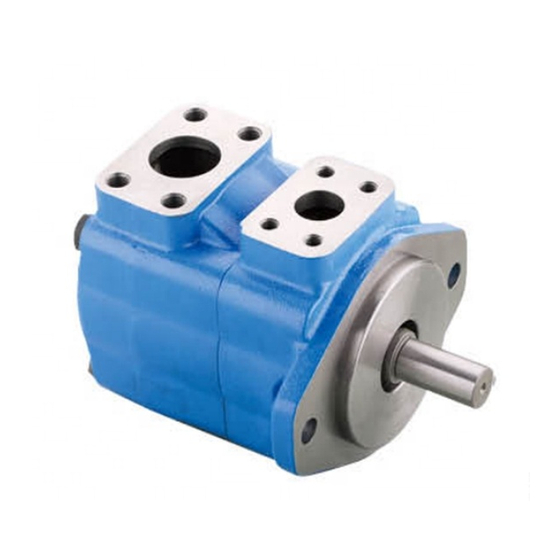
Section II – Description A. General 3. The single intra-vane pump with a 282/283 suffix is designed to operate at reduced noise levels, but still maintain the same reliability, operating characteristics, and service advantages of previous models. All sound reduction in the 282/283 series pump is accomplished within the cartridge kit. -
Page 5: Installation And Operating Instructions
Section IV – Installation and Operating Instructions A. Installation Drawings 5. NOTE For information on pickling, refer to 694. The installation drawings listed in Table 1 show operating 2. To minimize flow resistance and the possibility of characteristics, installation dimensions and port locations. leakage, only as many fittings and connections as are necessary for proper installation should be used. -
Page 6: Sound Levels
F. Sound Levels 10. G. Overload Protection 11. Although system noise levels can be reduced by modifying Relief valves limit pressure in the system to a prescribed pump design, fluid conditions also play a major part in maximum and protect components from excessive pressure. reducing system noise levels. -
Page 7: Product Life
F. Product Life 18. CAUTION The longevity of these products is dependent upon environment, duty cycle, operating parameters and Individual cartridge parts are not interchangeable system cleanliness. Since these parameters vary from with similar parts of previous design models. application to application, the ultimate user must Complete cartridge kits are interchangeable with determine and establish the periodic maintenance previous designs. -
Page 8: Overhaul
Section VI – Overhaul A. Service Tools 20. B. Unit Removal Standard Tools WARNING 1. One torque wrench with short extension and sockets. Select appropriate torque wrench according to cover screw specifications noted in Table 4. Turn off all electrical power and relieve hydraulic pressure. -
Page 9: Cleaning
c. Inspect bushing for wear and scoring. Wear on one side indicates that the pump and drive motor were not Spirolox Ring (31) aligned. See Figure 4. 2. Check bearing (25) for wear, looseness and pitted or cracked races. 3. Inspect the seal and bushing mating surfaces on shaft (26) for scoring and wear. -
Page 10: Start-Up
a. Line up the two cartridge kit pins (18) with the holes in inlet cover Inlet Direction of Rotor b. Install spline coupling (8) on end of shaft (26). rotation NOTE If a new shaft and coupling kit is required, install retaining ring (9) into coupling (8) prior to coupling installation. - Page 11 **VT (Thru Shaft Models) 23 24 14 13 21 19 27 28 Item Nomenclature Qty. Item Nomenclature Qty. Foot Bracket Kit Screw Inlet Support Plate Screw Cover Ring Screw Rotor Adapter Flange Vanes & Intra-Vanes “O” Ring Outlet Support Plate Spline Coupling Spirolox Ring Retaining Ring...
Need help?
Do you have a question about the Vickers 25V Series and is the answer not in the manual?
Questions and answers