Sign In
Upload
Download
Table of Contents
Contents
Add to my manuals
Delete from my manuals
Share
URL of this page:
HTML Link:
Bookmark this page
Add
Manual will be automatically added to "My Manuals"
Print this page
×
Bookmark added
×
Added to my manuals
Manuals
Brands
Eaton Manuals
Water Pump
70422
Parts and repair information
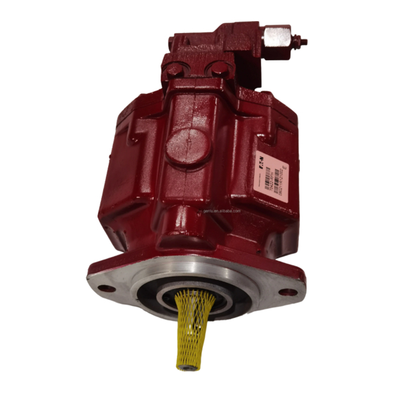
Eaton 70422 Parts And Repair Information
Medium duty piston pump
Hide thumbs
1
Table Of Contents
2
3
4
5
6
7
8
9
10
11
12
13
14
15
16
17
18
19
20
21
22
23
24
page
of
24
Go
/
24
Contents
Table of Contents
Bookmarks
Table of Contents
Table of Contents
Introduction
Identification
Tools Required
Parts Drawing
Parts List
Item 1 - Drive Shaft ID
Item 2 - Backplate Assembly
Item 4 - Compensator Assembly and Parts List
Factory Pre-Set Compensator Assemblies
Item 3 - Housing Identification
Item 5 - Rotating Kit
Mounting Kits
Product Number
Repair Information
Disassembly
Inspection
Reassembly
Start-Up Procedure
Fault - Logic Troubleshooting
Advertisement
Quick Links
1
Table of Contents
2
Identification
3
Item 1 - Drive Shaft ID
4
Item 5 - Rotating Kit
Download this manual
Eaton
®
Medium Duty Piston Pump
Parts and Repair
Information
Model 70423 or 70453
3
0 - 45 cm
/r [0 - 2.77 in
Displacement
Pressure or Pressure-Flow Compensated Piston Pumps
3
/r]
Model 70422 or 70452
0 - 38 cm
3
/r [0 - 2.32 in
Displacement
No. 6-631
January 1998
3
/r]
Table of
Contents
Previous
Page
Next
Page
1
2
3
4
5
Advertisement
Table of Contents
Need help?
Do you have a question about the 70422 and is the answer not in the manual?
Ask a question
Questions and answers
Related Manuals for Eaton 70422
Water Pump Eaton 704342 Repair Information
Medium duty piston pump, 40.6 cm3/r 2.48 in3/r displacement manually variable displacement piston pump (20 pages)
Water Pump Eaton 70344 Repair Information
Medium duty piston pump, 40.6 cm3/r 2.48 in3/r displacement manually variable displacement piston pump (20 pages)
Water Pump Eaton 72400 Repair Information
Medium duty piston pump (25 pages)
Water Pump Eaton 70122 Manual
(21 pages)
Water Pump Eaton 70160 Manual
Medium duty variable displacement piston pump (20 pages)
Water Pump Eaton 70160 Repair Information
Variable displacement piston pump (20 pages)
Water Pump Eaton 70360 Parts And Repair Information
Medium duty variable displacement piston pump (29 pages)
Water Pump Eaton 70523 Parts And Repair Information
Pressure or pressure-flow compensated piston pumps (20 pages)
Water Pump Eaton 70553 Parts And Repair Information
Pressure or pressure-flow compensated piston pumps (20 pages)
Water Pump Eaton 74624 Series Repair Information
Medium duty piston pump (13 pages)
Water Pump Eaton 70142 Repair Information
Medium duty piston pump (20 pages)
Water Pump Eaton 70145 Repair Information
Medium duty piston pump (20 pages)
Water Pump Eaton 74318 Repair Information
Medium duty piston pump (9 pages)
Water Pump Eaton 74348 Repair Information
Medium duty piston pump (9 pages)
Water Pump Eaton 70423 Parts And Repair Information
Medium duty piston pump (24 pages)
Water Pump Eaton 70453 Parts And Repair Information
Medium duty piston pump (24 pages)
This manual is also suitable for:
70452
70423
70453
Table of Contents
Save PDF
Print
Rename the bookmark
Delete bookmark?
Delete from my manuals?
Login
Sign In
OR
Sign in with Facebook
Sign in with Google
Upload manual
Upload from disk
Upload from URL


Need help?
Do you have a question about the 70422 and is the answer not in the manual?
Questions and answers