Table of Contents
Advertisement
Quick Links
Advertisement
Table of Contents

Subscribe to Our Youtube Channel
Summary of Contents for Major tech MT987
- Page 1 INSTRUCTION MANUAL MT987 20A MICRO-OHMMETER...
-
Page 3: Table Of Contents
Contents Page no 1. Introduction..................4 2. Safety Rules and Precautions ..............4 3. Instrument Structure.................5 4. Operation Method................6 4.1. Power Function.................6 4.2. Interface Introduction...............6 4.2.1. Main Interface..............6 4.2.2. Settings ................. 6 4.2.3. Resistance Test Interface..........6 4.2.4. View Interface..............7 4.2.5. Product Information Interface..........7 4.3. -
Page 4: Introduction
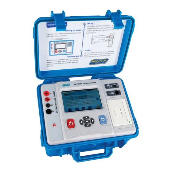
1. INTRODUCTION The MT987 DC Resistance Tester, also recognized as the Transformer DC Resistance Tester, DC Resistance Quick Tester, and Earth Continuity Tester, incorporates advanced microprocessor technology and utilizes the four-wire method for testing. It ensures a safe, precise, and reliable assessment of various electrical components. -
Page 5: Instrument Structure
• During measurement, DO NOT touch bare or uninsulated conductors or circuits under measurement. • Confirm that the connector plug of the test lead has been inserted into the tester’s interface correctly. • Do not measure in flammable or gaseous areas. •... -
Page 6: Operation Method
4. OPERATION METHOD 4.1. Power Function Press the "On/Off" key to switch the tester On or Off. 4.2. Interface Introduction 4.2.1. Main Interface 4.2.2. Settings 4.2.3. Resistance Test Interface... -
Page 7: View Interface
4.2.4. View Interface 4.2.5. Product Information Interface 4.3. Icon Description TEST Test Button Dimming Current Gear Setting Return Set Current Material Settings Delete Set Material Save Data Data Print SAVE Indicates that the data Confirm Deletion is saved successfully Bluetooth Button Cancel Test stop time setting Minus 1 step-by-step... -
Page 8: Battery Power Check
4.4. Battery Power Check 1. When turning the meter on and the low battery voltage symbol " " is displayed on the upper right corner of the LCD, it means that the battery is low, please charge it timeously. Only when the battery power is sufficient can the accuracy of the measurement be guaranteed. -
Page 9: Temperature Display
The automatic current display will be selected by default every time it is turned on. If you need to manually select other currents, please click the icon in the lower left corner to switch to the corresponding current display as indicated in the figure below: Click the icon to start the test. -
Page 10: Backlight And Auto Power Off Settings
4.7. Backlight and Auto Power Off Settings Backlight setting: Enter the setting interface, drag the icon to the left or right to adjust the brightness. Automatic shutdown setting: Press the left and right keys to select the automatic shutdown countdown of "OFF", "5 minutes", "10 minutes", "15 minutes", "20 minutes", "25 minutes"... -
Page 11: Data Query/Deletion/Print
4.9. Data Query/Deletion/Print On the main interface, click the "View" icon to enter the query interface for data query and deletion (as shown in the figure below). If the instrument has not saved any data, the interface will prompt "No saved data yet!"... -
Page 12: App And Pc Upper Computer Operation
loads within the default test stop time of 60 minutes, in the setting interface, click the icon in the lower left corner to enter the test stop time setting state to modify the time. The default time will be restored to 60 minutes each time the device is restarted. -
Page 13: Specifications
5. SPECIFICATIONS 5.1. Range and Accuracy 5.1.1. Temperature Measurement Accuracy Type Range Maximum Display Resolution Test Accuracy Temp probe -10.0°C to 60.0°C 60.0°C 0.1°C ±1.0°C Internal temp -10.0°C to 60.0°C 60.0°C 0.2°C ±1.0°C 5.1.2. Resistance Measurement Accuracy Measuring Current Measuring range Accuracy Resolution 10.0uΩ... -
Page 14: Technical Specifications
5.2. Technical Specifications Function Range Function Measures transformer DC resistance, transformer winding resistance, earth grid connection continuity, cable wire resistance, switch, connector, relay contact resistance, coil, motor, metal riveting resistance, metal components Interconnection resistance test, low value resistance test, contact resistance test, etc. Sample Type Optional Copper (Cu), Aluminium (Al), Iron (Fe), Gold (Au), Silver (Ag) material... -
Page 15: Quantity Of Standard Accessories
Major Tech is not responsible for other losses caused by use. Major Tech reserves the right to modify the content of the user manual. If there is any modification, no further notice will be given... - Page 16 MAJOR TECH (PTY) LTD South Africa Australia www.major-tech.com www.majortech.com.au sales@major-tech.com info@majortech.com.au...


Need help?
Do you have a question about the MT987 and is the answer not in the manual?
Questions and answers