Table of Contents
Advertisement
Quick Links
TITANMAX
User Manual
™
P/N 40880, 40881, 40885, 40887
NOTE: These Instructions do not cover the manifold attached to the instrument.
For instructions on use of the TITAN
4-Valve Manifold, please visit:
®
https://yellowjacket.com/product/titan-4-valve-test-and-charging-manifold/.
The Manifold Instructions are under the Documents tab.
REV A
Advertisement
Table of Contents

Related Manuals for yellow jacket TITANMAX 40880


Summary of Contents for yellow jacket TITANMAX 40880
- Page 1 TITANMAX User Manual ™ P/N 40880, 40881, 40885, 40887 NOTE: These Instructions do not cover the manifold attached to the instrument. For instructions on use of the TITAN 4-Valve Manifold, please visit: ® https://yellowjacket.com/product/titan-4-valve-test-and-charging-manifold/. The Manifold Instructions are under the Documents tab. REV A...
-
Page 2: Table Of Contents
Contents Chapter 1: ..............................1 Before You Start ............................1 1.1 Contacting Ritchie Engineering: ......................1 1.2 Safety Information: ..........................1 Chapter 2: ..............................3 Getting Started ............................3 2.1 Getting to Know Your TITANMAX ™ : ....................3 2.2 Turning the instrument On and Off: ....................3 2.3 Interacting with the Device: ........................ - Page 3 Chapter 4: ..............................19 Settings ..............................19 Settings Menus Overview ........................19 4.0 General Settings Menu ........................19 4.1 Refrigerant Settings Menu ........................ 19 4.2 Unit Settings Menu ........................... 20 4.2.1 Pressure Units: ........................20 4.2.2 Vacuum Units: ........................20 4.2.3 Temperature Units: ......................
-
Page 4: Chapter 1
Chapter 1: Before You Start 1.1 Contacting Ritchie Engineering: To order accessories, receive assistance, or locate the nearest YELLOW JACKET ® distributor. Corporate Office and Mailing Address: Ritchie Engineering Co, Inc. / YELLOW JACKET Products Division ® 10950 Hampshire Avenue South, Bloomington, MN 55438-2623 U.S.A. - Page 5 To avoid damage to equipment, follow these Do not operate the instrument around • guidelines: explosive gas, vapor, or dust. Do not allow pressures beyond the Various refrigerants have been • • specifications listed in this manual. intentionally excluded for very significant safety reasons.
-
Page 6: Chapter 2
Chapter 2: Getting Started 2.1 Getting to Know Your TITANMAX ™ Figure 1: TITANMAX ™ Front View Figure 2: TITANMAX ™ Rear View 1. Touchscreen Display 2. Power Button 3. RGB LED 4. Temperature Clamp Mounting Magnets 5. T1 Connector 6. -
Page 7: Interacting With The Device
2.3 Interacting with the Device: The TITANMAX ™ features a 5” full color resistive touchscreen for improved usability and durability. To interact with the device, use a finger or stylus to touch anywhere on the screen. All interactive buttons are conveniently displayed with the same raised button look as seen in Figures 4 &... -
Page 8: Connecting And Using The Vacuum Sensor
2.5 Connecting and Using the Vacuum Sensor: The TITANMAX ™ includes a (67044) YELLOW JACKET ® Vacuum Sensor, pictured in Figure 9, which can be used with this unit to measure the current depth of vacuum within a system. To connect the vacuum probe to the device use the VAC connector as shown in Figure 10. -
Page 9: Charging The Battery
2.7 Charging the Battery: To ensure maximum battery life, make sure the TITANMAX is charged before and after each job ™ session. To charge the device, connect the manifold TITANMAX to a power source via the provided data ™ transfer cable as pictured in Figure 12. When connected to a power source, the LED will turn a solid green. - Page 10 Figure 14: Micro-USB Location Figure 15: Connecting to the Micro-USB Data log files are stored as .csv files and are named with the following convention: Last 5 digits of the TITANMAX serial number, followed by a 3 digit sequential number 000 - 999.csv.
-
Page 11: Interpreting The Rgb Led
2.10 Interpreting the RGB LED: The LED on the front face of the device can display a variety of colors during normal operation. Below is a list of various colors and flashing schemes encountered during normal use. • Flashing Blue: The TITANMAX flashes blue every time it stores a data log ™... -
Page 12: Chapter 3
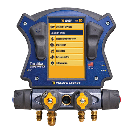
Chapter 3: Operation Menus 3.0 Main Menu Once the Language has been selected, the TITANMAX ™ will always start up on the Main Menu shown in Figure 17 below. Tap any of the six buttons labeled “Available Devices, Pressure/Temperature, Evacuation, Leak Test, Psychrometric , or Information”. -
Page 13: Interpreting The Pressure Analog Gauges
1. Battery Level Indicator 2. Currently Selected Pressure & Temperature Units 3. Currently Selected System Refrigerant – Refrigerant Settings Shortcut 4. Low Side Pressure & Temperature Measurement 5. High Side Pressure & Temperature Measurement 6. Current Menu Selection Display & Information Button 7. -
Page 14: Evacuation Menu
NOTE: Before connecting to the system, make sure to zero the pressure transducers at ambient pressure to ensure accurate pressure readings. To read about the transducer zeroing process, see page20. 3.2 Evacuation Menu 3.2.0 Overview: Once the refrigerant has been recovered from the system, the TITANMAX ™... -
Page 15: Operating The Evacuation Menu
300 seconds (approx. 5 minutes) and will begin again from the left side of the graph. 3.2.2 Operating the Evacuation Menu: Before beginning an evacuation, connect the YELLOW JACKET ® Vacuum Sensor (67044) to the VAC connector on the right side of the device VAC port. Connect the vacuum probe to the system at a sufficient distance from the vacuum pump such that it will not disturb the vacuum reading. -
Page 16: Pressure Hold Mode - Pressure Decay Test
3.3 Pressure Hold Mode – Pressure Decay Test 3.3.0 Overview: The TITANMAX ™ can be used to monitor a system leak through a drop in positive pressure. The pressure decay test displays the current system pressure (Current), the initial pressure (Start), the change in pressure (pressure drop), the Limit Pressure (Allowable), and the Rate of Change (change/min). -
Page 17: Interpreting The Pressure Decay Graph
3.3.1 Interpreting the Pressure Decay Graph: Pressure Decay menu features a line graph which plots current system pressure readings in real time. System pressure is plotted on a linear scale. The current system pressure graph utilizes a leader line to plot new data from left to right. Old data is conveniently displayed to the right of the leader line such that it can be compared to newer data. - Page 18 during the test (shown in Figure 23). The current system pressure will be stored as START. During the pressure decay test, CURRENT will adjust as the current system pressure changes. Pressure Drop will adjust to reflect the change between the initial system pressure and current system pressure.
-
Page 19: Interpreting The Pressure Leak Graph
Figure 26: LEAK TEST Menu 1. Battery Life Indicator 2. Session Timer 3. Currently Selected Vacuum Units – Unit Settings Menu Shortcut 4. Settings Button 5. Main Menu Button 6. Currently Selected Menu 7. Initial Pressure 8. Pressure Limit 9. Start/ Cancel Test Button 10. -
Page 20: Psychometric Menu
3.4 Psychometric Menu 3.4.0: Overview: The Psychrometric session (Figure 27) displays: Relative humidity, dry bulb temperature, wet bulb temperature, and dew point temperature from 2 YJACK DEW ® psychrometric probes, that measure relative humidity in supply air and return air in HVAC systems. - Page 21 Figure 29: Rated Capacity Input Screen Figure 28: Volumetric Air Input screen Once the System Settings have been entered the calculated Current Capacity and System Efficiency % will be displayed.
-
Page 22: Chapter 4
Chapter 4: Settings Settings Menus Overview The TITANMAX ™ settings menus are separated into five menus: refrigerant settings, unit settings, zero the on board pressure sensors, device settings, and data logging. While on any modes screen or the modes menu, the general settings menu can be quickly accessed by tapping the gear icon in the top right corner. -
Page 23: Unit Settings Menu
4.2 Unit Settings Menu The unit settings menu, shown in Figure 33, can be used to quickly change currently selected units. This menu can be accessed by tapping the units in the general settings menu to select a new pressure, vacuum, temperature, power or flow rate unit, tap the desired unit within the corresponding list. -
Page 24: Device Settings Menu
4.4 Device Settings Menu The device settings menu, shown in Figure 34, can be used to adjust a variety of device settings including display brightness, backlight timer, and auto off timer. To access the device settings menu, tap the “Device Settings” button in the general settings menu. To adjust the display brightness, tap and drag the slider bar below brightness until the desired brightness is displayed. -
Page 25: Logs Menu
4.5 LOGS Menu The Logs menu, shown in Figure 35, can be used to change Sessions to record. This menu can be accessed by tapping the LOGS button in the general settings menu to select a rate, tap the desired interval within the logging rate bar. -
Page 26: Chapter 5: Yjack View ® App Integration
Chapter 5: YJACK VIEW App Integration ® 5.0 Overview: The TITANMAX features a Bluetooth low energy radio and is fully compatible with both ™ ® the iOS and Android YJACK VIEW ® Apps V5.1 or later. The YJACK VIEW ® app in conjunction with the TITANMAX ™... -
Page 27: Chapter 6
Chapter 6: Maintenance 6.0 Overview: Basic operator maintenance is covered in this chapter. For more extensive maintenance and for repair, contact Ritchie Customer Service. See Chapter 1 for contact information. 6.1 General Maintenance: Since this instrument may be used in the presence of a wide range of chemical liquids and vapors, it is recommended that the case be cleaned often with a damp cloth and mild detergent such as dish soap. -
Page 28: Software Updates
6.4 Software Updates: Details related to software updates are available online at www.yellowjacket.com or by contacting Ritchie Engineering. See Chapter 1 for contact information. Chapter 7: Device Specifications Physical Specifications Table 7-1: Maximum Pressure 740 psia (51.0 bar) Operating Temperature 140 to -4°F (60 to -20°C) Storage Temperature 140 to -4°F (60 to -20°C) -
Page 29: Chapter 8
Chapter 8: Troubleshooting Guide TABLE 8-1 TITANMAX ™ Troubleshooting Problem Possible Cause(s) Possible Solution(s) Screen does not display Power saving backlight timer Check backlight timer setting anything has expired due to inactivity Tap power button or anywhere on display to power on backlight Device is not powering on Make sure manifold is sufficiently charged Screen is damaged... - Page 30 Problem Possible Cause(s) Possible Solution(s) Vacuum reading incorrect/not Vacuum probe barrel Check vacuum probe connection to manifold displaying connector not fully seated Vacuum probe/cable damaged Call technical support Vacuum probe jacks damaged Call technical support Probe not properly attached to Check vacuum probe connection to system system Vacuum probe plugged into...
- Page 31 Problem Possible Cause(s) Possible Solution(s) Manifold not charging, LED USB cable not connected Check USB connection to manifold and power source not solid green properly USB cable damaged Use alternate USB cable Device fully charged No action Manifold damaged Call technical support Unable to receive Bluetooth Device is not powered on Make sure manifold is powered on...
Need help?
Do you have a question about the TITANMAX 40880 and is the answer not in the manual?
Questions and answers